Creating Bar Bending schedule, Different Door types, and Creation of standard drawing templates using AutoCad
AIM:
To create template with inserting text and attributes and required objects by using Auto CAD
INTRODUCTION:
XLine: It means construction line. It has infinty edges we used for making wall. By typing "XL" on command line we envoke this tool.
Line: It connects one point to another points. Used to draft various elements.
Trim: This modification tool helps to cut extended edges on the drawing. And to trim inbetween two line or elements. "TR" command to envoke this tool.
Extend: It is also a modification tool, if we have some broken edges or need to extend some portion towards anonther element. "EX" command to envoke the tool.
Offset: Offset the existing element with certain distance. this tool avoid to create new parallel elements.
Layer: Each and every elements has unique property and unique style. This layer tool helps to organize those. Line weight, line style, colour gradient, freeze, lock. it has numerous benefits in Auto CAD drafting.
Hatch: Hatching helps to fill the voids with certain texture on it. If we draft wall means, we mention the brickwork details with the help of hatching.
Circle: Used to make circle elements in the sheet. Type "C" to envoke this tool. Here it is used to draft door.
Polygon: Used to make rectangle or polygons with number of sides.
PROCEDURE:
A:
step-1: Type "UN" to set units of the drawing set.
step-2: Type "LIMITS" to enter right upper and left lower corner of the drawing sheet.
step-3: Type "L" to envoke line tool and press anywhere in the sheet to draw accordingly.
step-4: Type "O" to envoke offset tool with specific distance from the initial line.
step-5: Type "O" offset to create all rows and columns as per given drawing to make drawing template.
step-6: Select outer layer of line tool and change line weight in to 0.3 mm in the ribbon tab.
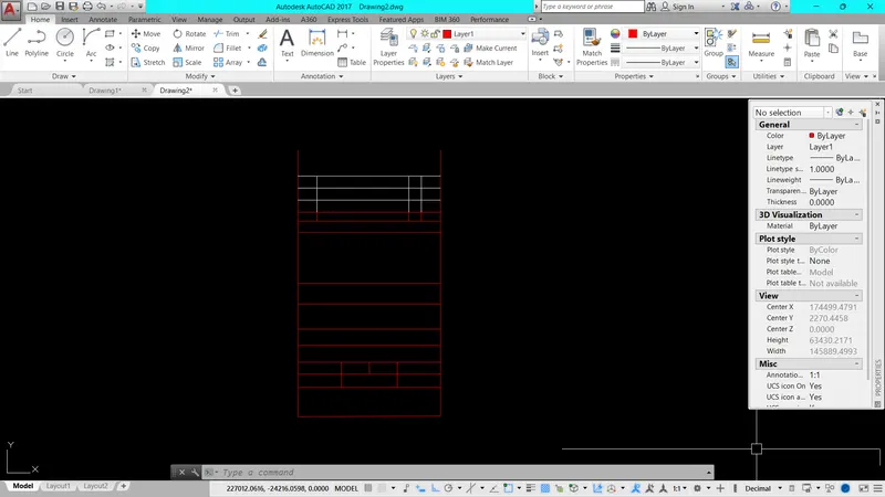
step-7: Type "MT" to envoke mtext and put text height and angle of the text.
step-8: Type "CO" to copy the text and paste it wherever the text element required.
step-9: Type "ED" to edit the text
B:
step-1: Type "UN" to set units of the drawing set.
step-2: Type "LIMITS" to enter right upper and left lower corner of the drawing sheet.
step-3: Type "L" to envoke line tool and press anywhere in the sheet to draw accordingly.
step-4: Type "O" to envoke offset tool with specific distance from the initial line.
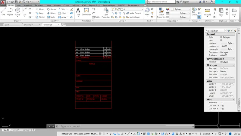
step-5: Type "O" offset to create all rows and columns as per given drawing to make drawing template.
step-6: Select the line weight at 0.3 mm and match the required texts.
step-7: Type "MT" to envoke mtext and put text height and angle of the text.
step-8: Type "CO" to copy the text and paste it wherever the text element required.
step-9: Type "ED" to edit the text.
RESULT:
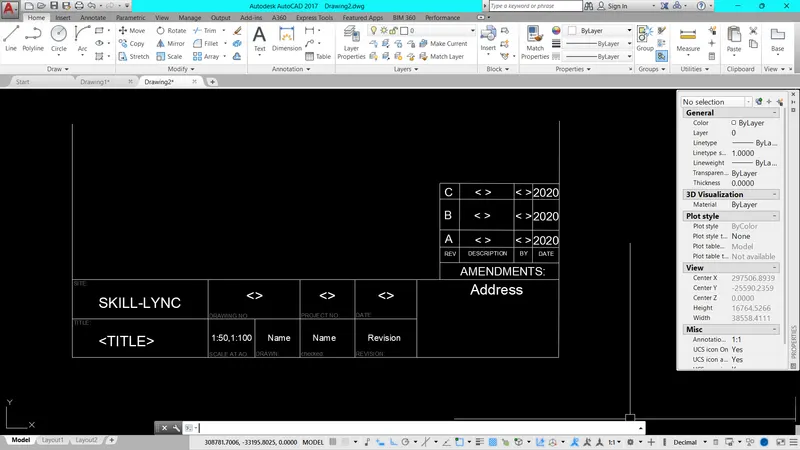
Created the drawing templates with texts and attributes by using AutoCAD.
AIM:
To create the doors from given figure as per standard dimensions and block them by using Auto CAD
INTRODUCTION:
XLine: It means construction line. It has infinty edges we used for making wall. By typing "XL" on command line we envoke this tool.
Line: It connects one point to another points. Used to draft various elements.
Trim: This modification tool helps to cut extended edges on the drawing. And to trim inbetween two line or elements. "TR" command to envoke this tool.
Extend: It is also a modification tool, if we have some broken edges or need to extend some portion towards anonther element. "EX" command to envoke the tool.
Offset: Offset the existing element with certain distance. this tool avoid to create new parallel elements.
Layer: Each and every elements has unique property and unique style. This layer tool helps to organize those. Line weight, line style, colour gradient, freeze, lock. it has numerous benefits in Auto CAD drafting.
Hatch: Hatching helps to fill the voids with certain texture on it. If we draft wall means, we mention the brickwork details with the help of hatching.
Circle: Used to make circle elements in the sheet. Type "C" to envoke this tool. Here it is used to draft door.
Polygon: Used to make rectangle or polygons with number of sides.
PROCEDURE:
step-1: Type "UN" to set units of the drawing set.
step-2: Type "LIMITS" to enter right upper and left lower corner of the drawing sheet.
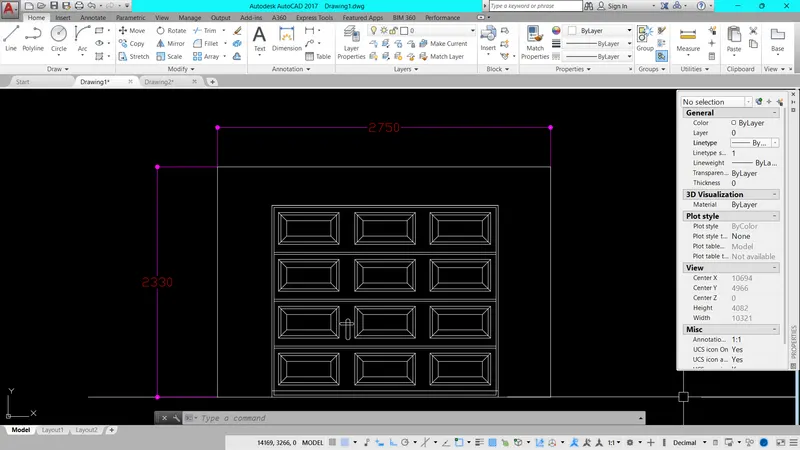
step-3: Type "XL" to envoke construction line tool and press anywhere in the sheet to draw horizontal and vertical accordingly.
step-4: Type "TR" trim construction line to create doors.
step-5: Type "O" to envoke offset tool with specific distance from the initial line to the +ve X-direction.
step-6: Type "O" to envoke offset tool with specific distance from the initial line to the -ve Y-direction.
step-7: Type "L" to envoke line tool to create door inner frames and models.
step-8: Type "B" to block the one model of door inner works.
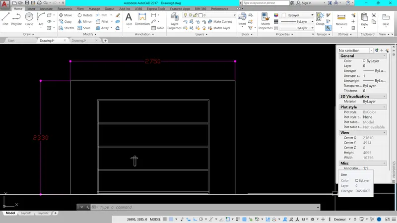
step-9: Type "CO" to copy the object and paste it to create entire door unit.
step-10: Type "L" to create Door handle.
step-11: Type "DIMLIN" to mark linear dimensions of doors.
step-12: Type "DT" with proper text height and text plotted angle to enter title of the drawing.
step-13: Type "ERASE" to erase all the objects that not necessary to create door 2.
step-14: Type "B" to block door 2.
RESULT:
Create doors for the industry sheds with proper dimensions by using Auto CAD.
AIM:
To create the symbol as a block with the legend from given figure as per standard dimensions by using Auto CAD
INTRODUCTION:
XLine: It means construction line. It has infinty edges we used for making wall. By typing "XL" on command line we envoke this tool.
Line: It connects one point to another points. Used to draft various elements.
Trim: This modification tool helps to cut extended edges on the drawing. And to trim inbetween two line or elements. "TR" command to envoke this tool.
Extend: It is also a modification tool, if we have some broken edges or need to extend some portion towards anonther element. "EX" command to envoke the tool.
Offset: Offset the existing element with certain distance. this tool avoid to create new parallel elements.
Layer: Each and every elements has unique property and unique style. This layer tool helps to organize those. Line weight, line style, colour gradient, freeze, lock. it has numerous benefits in Auto CAD drafting.
Hatch: Hatching helps to fill the voids with certain texture on it. If we draft wall means, we mention the brickwork details with the help of hatching.
Circle: Used to make circle elements in the sheet. Type "C" to envoke this tool. Here it is used to draft door.
Polygon: Used to make rectangle or polygons with number of sides.
PROCEDURE:
step-1: Type "UN" to set units of the drawing set.
step-2: Type "LIMITS" to enter right upper and left lower corner of the drawing sheet.
step-3: Type "POLYGON" select 8 number sides to create octagon with the type of outscribed circle.
step-4: Type "L" to draft switch portion of the drawing.
step-5: Type "CO" copy the element we drew and paste it near by in the drawing sheet for creating double gang switch.
step-6: Type "O" offset the switch portion and to create double gang switch.
step-7: Type "CO" copy the element we drew and paste it near by in the drawing sheet for creating triple gang switch.
step-8: Type "O" offset the switch portion and to create triple gang switch.
step-9: Type "CO" copy the element we drew and paste it near by in the drawing sheet for creating single gang twoway switch.
step-10: Type "DONUT" to create shaded portion in the symbol.
step-11: Type "O" offset the switch portion and to create double gang twoway switch.
step-12: Type "CO" copy the element we drew and paste it near by in the drawing sheet for creating triple gang twoway switch.
step-13: Type "O" offset the switch portion and to create triple gang two way switch.
step-14: Type "CO" copy the element we drew and paste it near by in the drawing sheet for creating switch cross.
step-15: Type "O" offset the switch portion and to create switch cross.
step-16: Type "MI" use mirror tool to create all sides of crosses.
step-17: Type "CO" copy switch cross and paste to create switch serial symbol.
step-18: Type "ERASE" erase the two switch portion for creating serial symbol.
step-19: Type "L" to create line base for socket symbol.
step-20: Type "A" Arc to select center of the arc and give start and end point of the arc for creating single socket.
step-21: Type "CO" copy the single socket to create double socket symbol.
step-22: Type "CO" copy the single socket to create single socket for lamp.
step-23: Type "L" line tool to draft line element in the top portion of the single socket to draft single socket for lamp.
step-24: Type "CO" copy single socket for lamp to create floor single socket for lamp
step-25: Type "REC" to envoke rectangle tool to create rectangle portion around the single socket for the lamp.
step-26: Type "CO" single socket to create floor socket single.
step-27: Type "CO" double socket to create floor socket double.
step-28: Type "REC" to envoke rectangle tool to create rectangle portion around the floor socket double.
step-29: Type "CO" floor socket double to create floor socket single and telephone.
step-30: Type "ERASE" to erase double socket element.
step-31: Type "POLYGON" select three sides and draft telephone symbol.
step-32: Type "CO" Floor socket single and telephone to draft floor socket double and telephone.
step-33: Type "CO" single socket paste in floor socket single and telephone object.
step-34: Type "POLYGON" select three sides to create telephone socket.
step-35: Type "CO" telephone socket and type "DT" text TV on it to draft internet socket.
step-36: Type "CO" telephone socket and type "DT" text TV on it to create TV socket.
step-37: Type "CO" telephone socket and type "DT" text W on it to create Weather socket.
step-38: Type "L" line tool to create dect base station.
step-39: Type "C" to create circle for wall bracket.
step-40: Type "L" line tool to draft other remaining elements in the wall bracket.
step-41: Tyoe "L" line tool to create picture lamp.
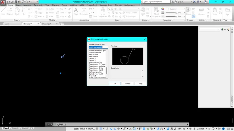
step-42: Type "B" to open block dialogue box and select the objects for blocking.
step-43: Type "B" block the symbols by seperate manner.
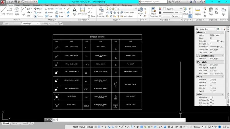
step-44: Type "XL" to envoke construction line tool and press anywhere in the sheet to draw horizontal and vertical accordingly.
step-45: Type "TR" trim construction line to create rows and columns.
step-46: Type "O" to envoke offset tool with specific distance from the initial line to the +ve X-direction.
step-47: Type "O" to envoke offset tool with specific distance from the initial line to the -ve Y-direction.
step-48: Type "MT" to envoke mtext and put text height and angle of the text.
step-49: Type "CO" to copy the text and paste it wherever the text element required.
step-50: Type "ED" to edit the text.
RESULT:
Created each symbol as blocks and also created symbol legends for reference purposes by using Auto CAD.
AIM:
To create the door type for residential building as a block with proper dimensions from the given figure by using Auto CAD
INTRODUCTION:
XLine: It means construction line. It has infinty edges we used for making wall. By typing "XL" on command line we envoke this tool.
Line: It connects one point to another points. Used to draft various elements.
Trim: This modification tool helps to cut extended edges on the drawing. And to trim inbetween two line or elements. "TR" command to envoke this tool.
Extend: It is also a modification tool, if we have some broken edges or need to extend some portion towards anonther element. "EX" command to envoke the tool.
Offset: Offset the existing element with certain distance. this tool avoid to create new parallel elements.
Layer: Each and every elements has unique property and unique style. This layer tool helps to organize those. Line weight, line style, colour gradient, freeze, lock. it has numerous benefits in Auto CAD drafting.
Hatch: Hatching helps to fill the voids with certain texture on it. If we draft wall means, we mention the brickwork details with the help of hatching.
Circle: Used to make circle elements in the sheet. Type "C" to envoke this tool. Here it is used to draft door.
Polygon: Used to make rectangle or polygons with number of sides.
PROCEDURE:
step-1: Type "UN" to set units of the drawing set.
step-2: Type "LIMITS" to enter right upper and left lower corner of the drawing sheet.
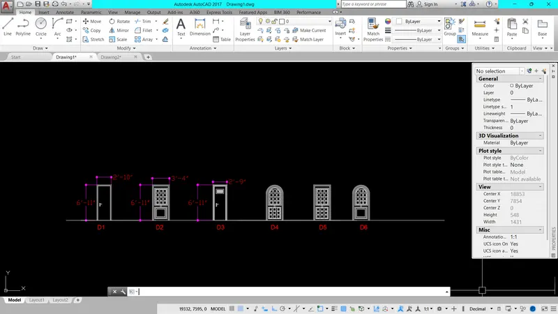
step-3: Type "L" to envoke line tool with the length of 6'11"
step-4: Select specific second length of 2'10".
step-5: Select third specific distance of 6'11"
step-6: Type "O" offset to draft frame of the door.
step-7: Type "DIML" to mark linear dimensions of the drawing.
step-8: Type "DT" to enter text object in the drawing.
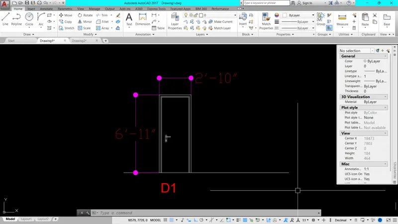
step-9: Type "L" to envoke line tool with the length of 6'11"
step-10: Select specific second length of 3'4".
step-11: Select third specific distance of 6'11"
step-12: Type "O" offset to draft frame of the door.
step-13: Type "L" to draft door inner frames of the door.
step-14: Type "DIML" to mark linear dimensions of the drawing.
step-15: Type "DT" to enter text object in the drawing.
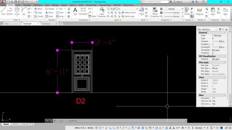
step-16: Type "L" to envoke line tool with the length of 6'11"
step-17: Select specific second length of 2'9".
step-18: Select third specific distance of 6'11"
step-19: Type "O" offset to draft frame of the door.
step-20: Type "L" to draft door inner frames of the door.
step-21: Type "H" hatch the particular area in the door.
step-21: Type "DIML" to mark linear dimensions of the drawing.
step-22: Type "DT" to enter text object in the drawing.
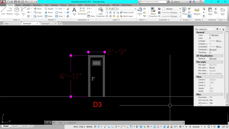
step-23: Type "L" to envoke line tool to draft height of the door.
step-24: Type "O" offset to draft entire outer layer of door.
step-25: Type "L" to draft door inner frames of the door.
step-26: Type "F" to select outer layers and create arc portion.
step-27: Type "DT" to enter text object in the drawing.
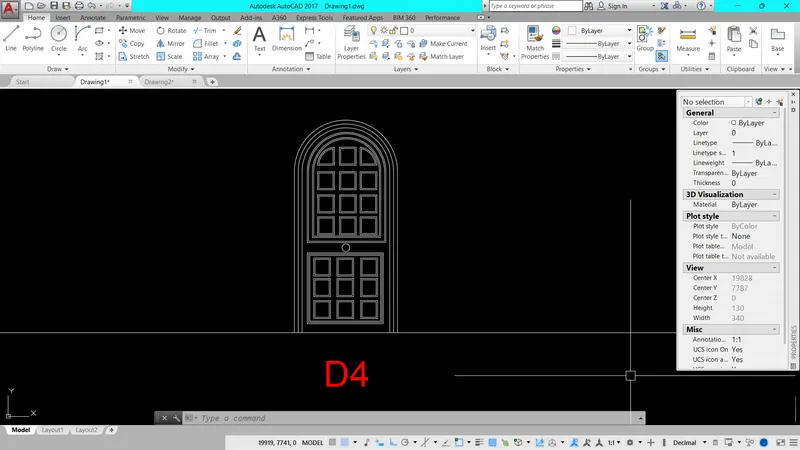
step-28: Type "L" to envoke line tool to draft height of the door.
step-29: Type "O" offset to draft entire outer layer of door.
step-30: Type "L" to draft door inner frames of the door.
step-31: Type "F" to select outer layers and create arc portion.
step-32: Type "DT" to enter text object in the drawing.
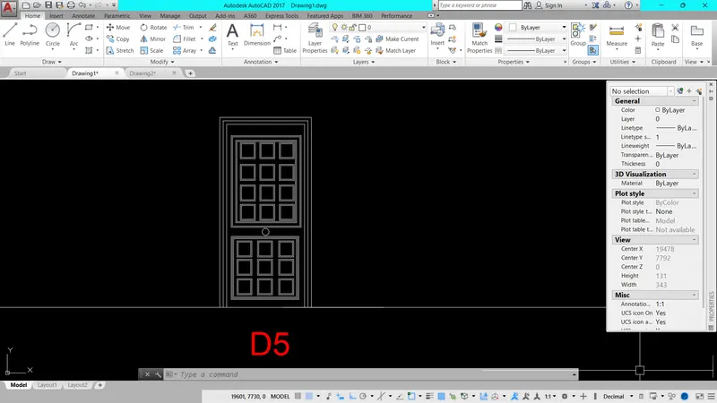
step-28: Type "CO" D4 to paste near by in the drawing
step-29: Type "ERASE" to erase all unnecessary elements to create D6.
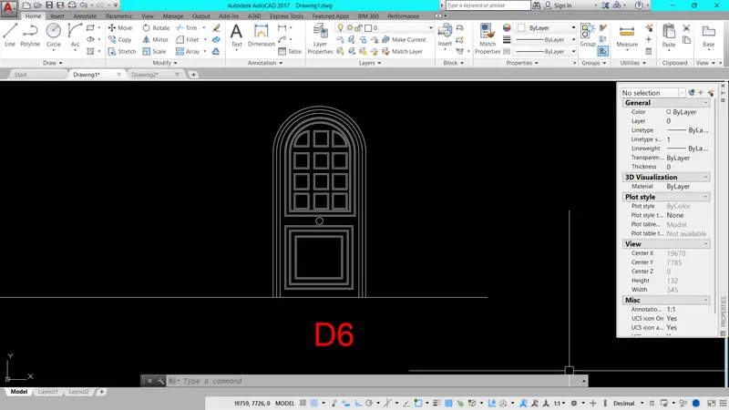
RESULT:
Created door of the residential building with proper dimensions and blocks by using Auto CAD.
AIM
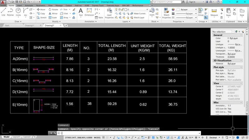
To create the bar bending schedule as shown in figure by using Auto CAD.
INTRODUCTION:
XLine: It means construction line. It has infinty edges we used for making wall. By typing "XL" on command line we envoke this tool.
Line: It connects one point to another points. Used to draft various elements.
Trim: This modification tool helps to cut extended edges on the drawing. And to trim inbetween two line or elements. "TR" command to envoke this tool.
Extend: It is also a modification tool, if we have some broken edges or need to extend some portion towards anonther element. "EX" command to envoke the tool.
Offset: Offset the existing element with certain distance. this tool avoid to create new parallel elements.
Layer: Each and every elements has unique property and unique style. This layer tool helps to organize those. Line weight, line style, colour gradient, freeze, lock. it has numerous benefits in Auto CAD drafting.
Hatch: Hatching helps to fill the voids with certain texture on it. If we draft wall means, we mention the brickwork details with the help of hatching.
Circle: Used to make circle elements in the sheet. Type "C" to envoke this tool. Here it is used to draft door.
Polygon: Used to make rectangle or polygons with number of sides.
PROCEDURE:
step-1: Type "UN" to set units of the drawing set.
step-2: Type "LIMITS" to enter right upper and left lower corner of the drawing sheet.
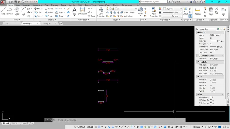
step-3: Type "L" line tool to create reinforment drawing
step-4: Type "F" fillet with radius of 9D.
step-5: Type "DIML" to mark all the dimensions required in the drawing.
step-6: Type "XL" to envoke construction line tool and press anywhere in the sheet to draw horizontal and vertical accordingly.
step-7: Type "TR" trim construction line to rows and columns.
step-8: Type "O" to envoke offset tool with specific distance from the initial line to the +ve X-direction.
step-9: Type "O" to envoke offset tool with specific distance from the initial line to the -ve Y-direction.
step-10: Type "MT" to envoke mtext and put text height and angle of the text.
step-11: Type "CO" to copy the text and paste it wherever the text element required.
step-12: Type "ED" to edit the text.
RESULT:
Created the bar bending schedule as shown in figure with blocks by using Auto CAD.