Creating Bar Bending schedule, Different Door types, and Creation of standard drawing templates using AutoCad
1. Create the templates as shown in Figures. Take the size of the title block as per industry standards or you can assume it as per the size of the paper. Use text and attributes wherever required. After creating the title block you need to save it as a block with names: Custom1_titleblock and Custom2_titleblock, respectively.
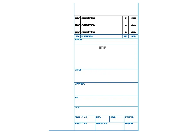
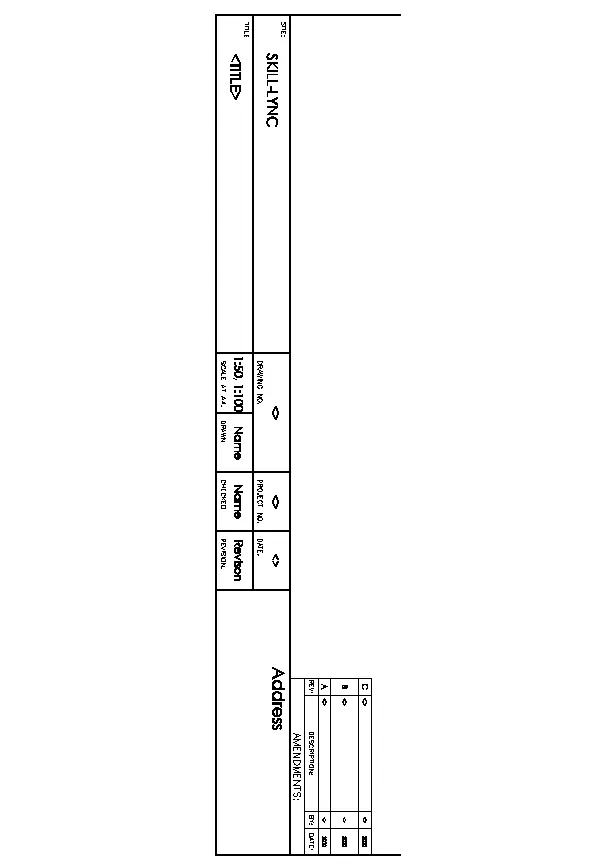
Aim:
To create the drawing template as shown in figure by using the AutoCAD software
Introduction:
Create the templates as shown in Figures. Take the size of the title block as per industry standards or you can assume it as per the size of the paper. Use text and attributes wherever required. After creating the title block you need to save it as a block with names: Custom1_titleblock and Custom2_titleblock, respectively.
Procedure:
Step-1: To set the units
- First of all set the units for sketch the template as given in the question
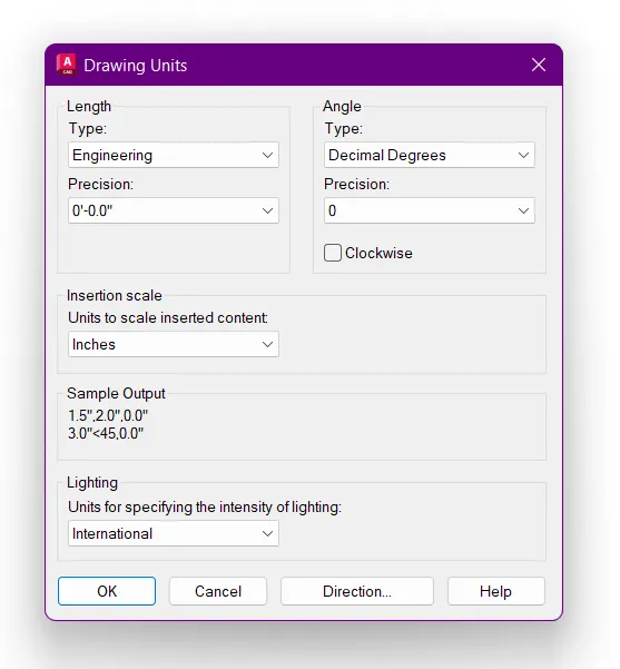
- Type UN for units in command box and get the dialogue box like as shown in below
- Then, here using the length type is Engineering
- Precision is 0'-0.0"
- Insertion scale is Inches
- Finally click OK
Step-2: To set the text
- Here, take the font name is Calibri
- Height is 10" for texting the contents
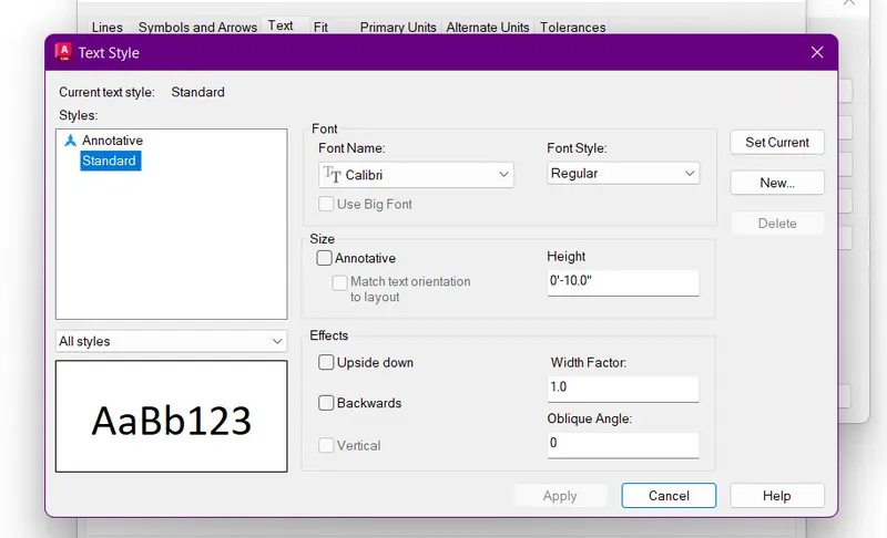
- Finally click Apply - Set Current and then click Close
Step-3: To create the layer properties
- Click the Layer properties and then, right click the layer and click new layer
- Insert the layer for give a identification for the line properties
- Here, give a line name, line color and line weight as i want
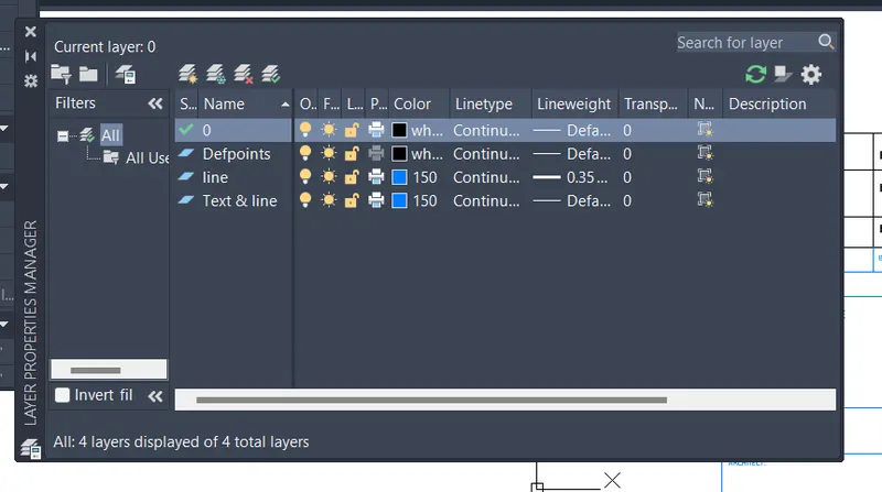
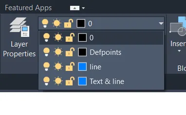
- Using these properties then, click the lines and then give a identification to the lines
Step-4: Sketch the templates
- Here, using the Line command for draw the outlines for the templates
- Next using the MText command for give a names for individual boxes
- Using the Move command for align the texts in the box as given in the question
- Finally using the Layer properties to the all lines where i want to give the layer properties
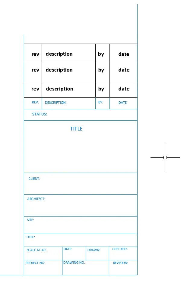
- Here, also using those commands are used in this template also
- Atlast using the snipping tool to take the screenshot of templates
- The shortcut is Windoes key+Shift+S
- Finally upload the figures for reference
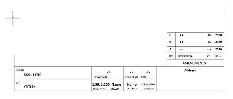
Result:
The drawing templates are sketched as given in the question drawing and assuming the all properties by using the AutoCAD software
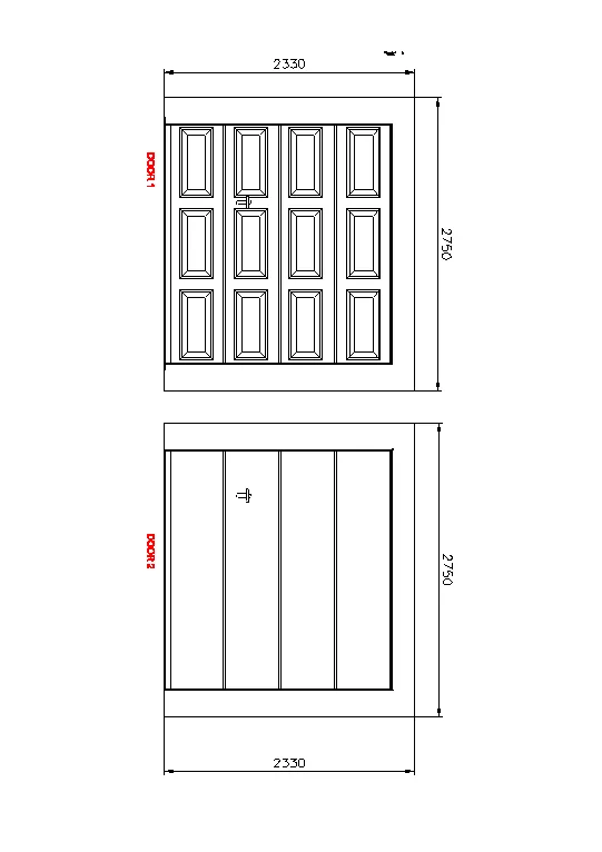
2. Create the doors type for warehouse as shown in the Figure. You need to create each door type as per standard size or given dimensions. Create the blocks of this door type after creating them.
Aim:
To create the doors type for warehouse as shown in the figure using the AutoCAD software
Introduction:
Create the doors type for warehouse as shown in the Figure. You need to create each door type as per standard size or given dimensions. Create the blocks of this door type after creating them.
Procedure:
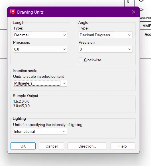
step-1: To set units
- Using the UN for unit command to draw the doors
- Here, using the line legth type is Decimal
- The precision is 0.0
- And then, take the Insertion scale is Millimeters
Step-2: To set the point type
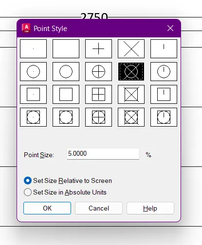
- The shortcut of point style is DDPTYPE
- Then, select as shown in below figure for divide the lines for draw the panels in the doors
- Click OK
Step-3: To draw the door drawing
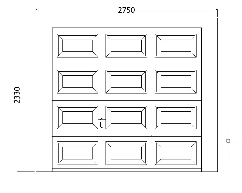
- The door is drawn using the given dimension
- Here, using the Line command and Rectangle command for draw this door drawing
- And Copy command for take the multiples of the panels
- Finally using the Dimlinear command for take the dimension of the door
- Here, using the Layer properties for text in red color as in the layer
- Using MText command for give a name for the doors
- Copy the door 1 for reference to the door 2 and delete all panels in the door 2 then, finish the drawing
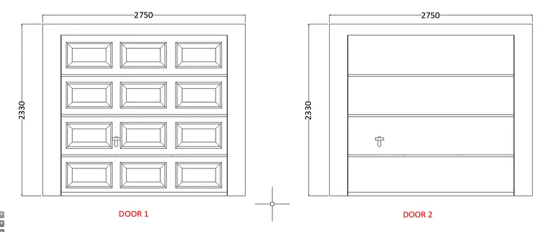
- Atlast using the snipping tool to take the screenshot of templates
- The shortcut is Windoes key+Shift+S
- Finally upload the figures for reference
Result:
The doors type for warehouse drawing drawn using to refer the given dimensions to draw the doors and using the AutoCAD 2023 software
3. Create each symbol as a block with the name given in the legend. After creating the blocks arrange them in the legend as shown in the Figure.
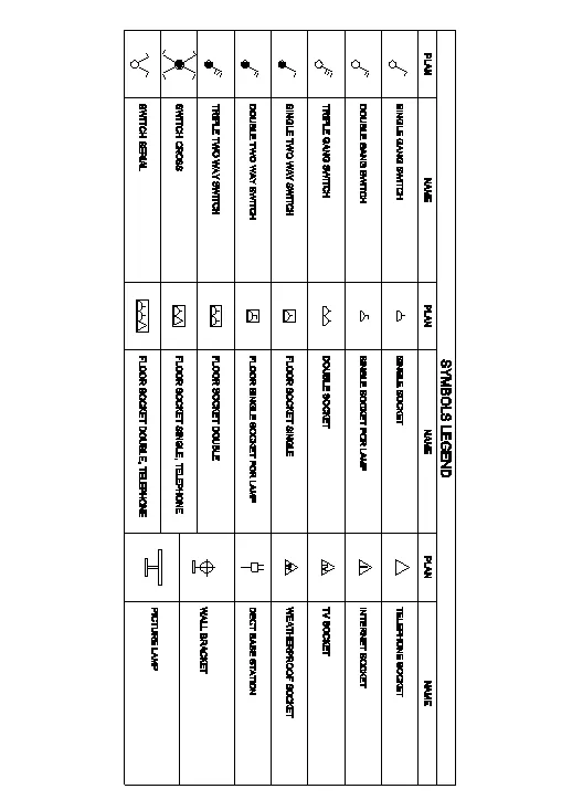
Aim:
To create each symbol as a block with the name given in the legend by using the AutoCAD software
Introduction:
Create each symbol as a block with the name given in the legend. After creating the blocks arrange them in the legend as shown in the Figure.
Procedure:
- In this table i am using same drawing sheet for sketch this symbol legend
- The text and the table sizes are assumption only
- Here, using the Line command and the MText command give a symbol name
- Next edit text to give a bold type of text
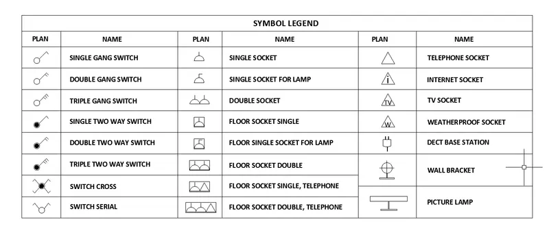
- Here, to draw the all symbols in this table to using the commands of Line, Circle, Rectangle, Hatch (Solid) and then Polygon for create the triangle
- MText command for text the name of the symbol
- Next, using Scale command for scaling the texts
- And then, using the Copy command to copy the lines in the table
- Atlast using the snipping tool to take the screenshot of templates
- The shortcut is Windoes key+Shift+S
- Finally upload the figures for reference
Result:
The creation of each symbol as a block with the name given in the legend by using the AutoCAD 2023 software
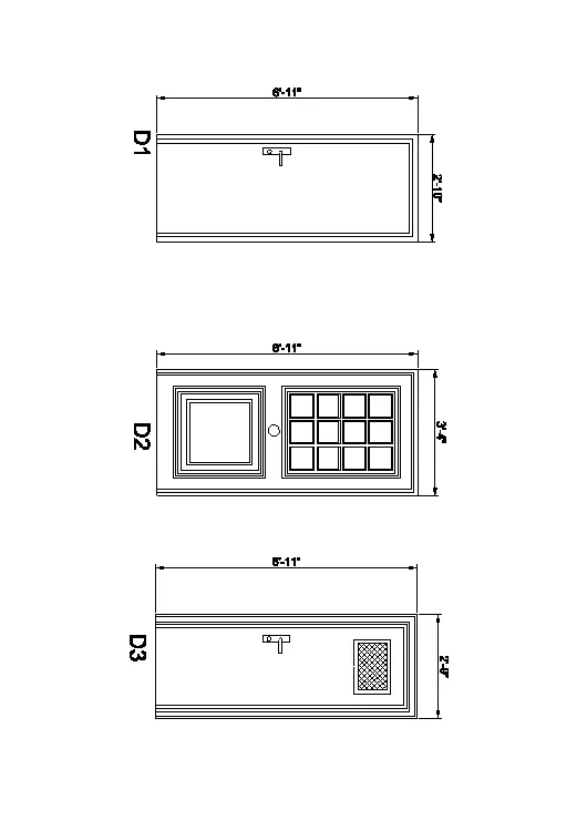
4. Create the door type for residential building as a block. Save the name of the blocks as type. Use given dimensions or assume dimensions as per industry standards.
Aim:
To create the door type for residential building as a block by using the AutoCAD software
Introduction:
Create the door type for residential building as a block. Save the name of the blocks as type. Use given dimensions or assume dimensions as per industry standards.
Procedure:
Step-1: To set the units
- First of all set the units for sketch the template as given in the question
- Type UN for units in command box and get the dialogue box like as shown in below
- Then, here using the length type is Engineering
- Precision is 0'-0.0"
- Insertion scale is Inches
- Finally click OK
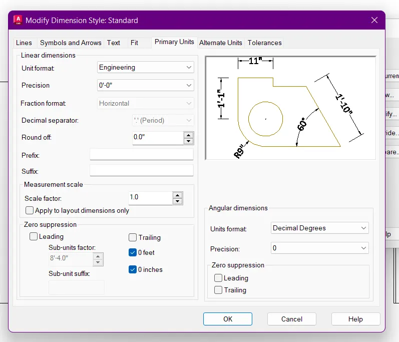
Step-2: To set the Dimension style
- First type DIMSTYLE in command search box
- Then Click Modify for the dimension style which type i want
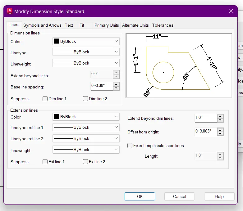
- Select Line - Increase the line spacing and extand beyond dim lines and the offset from origin
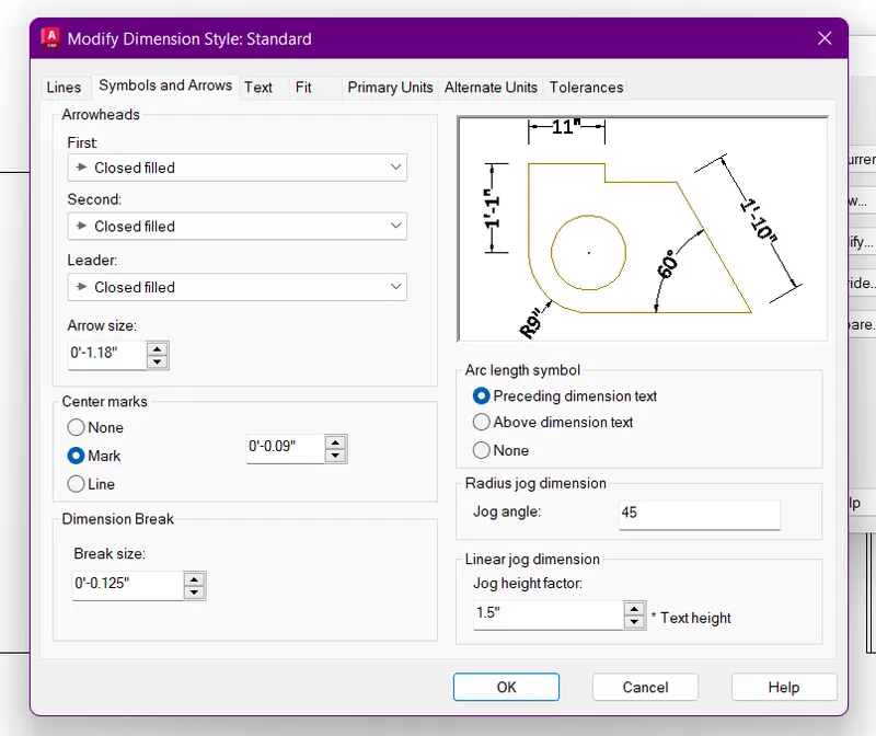
- Select Symbols and Arrows - Increase the arrow size
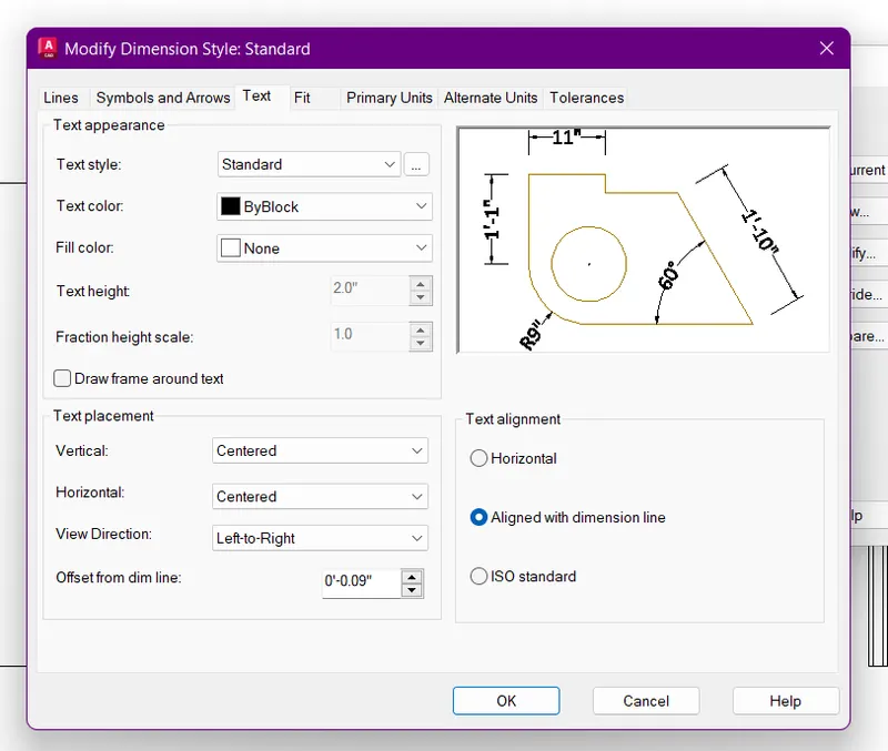
- Select Text - give a text height is 2"
- Then select the Primary units - select the unit format is Engineering and precision is 0'-0"
Step-3: To draw the doors
- Here, i have drawn using the Polyline command for draw the out line of the door
- And measure the door size using the Dimlinear command
- And using Offset command - select Through and Multiple
- Drag the mouse point and select where i want
- Draw the panels in the door by using the Rectangle command
- Then, DDPTYPE command for deviding the line to the square panel
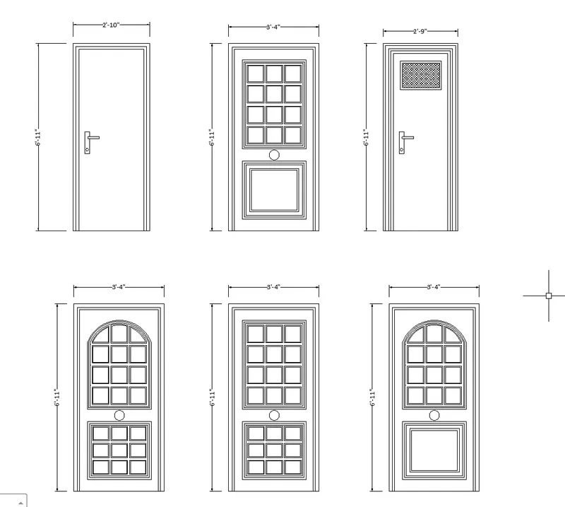
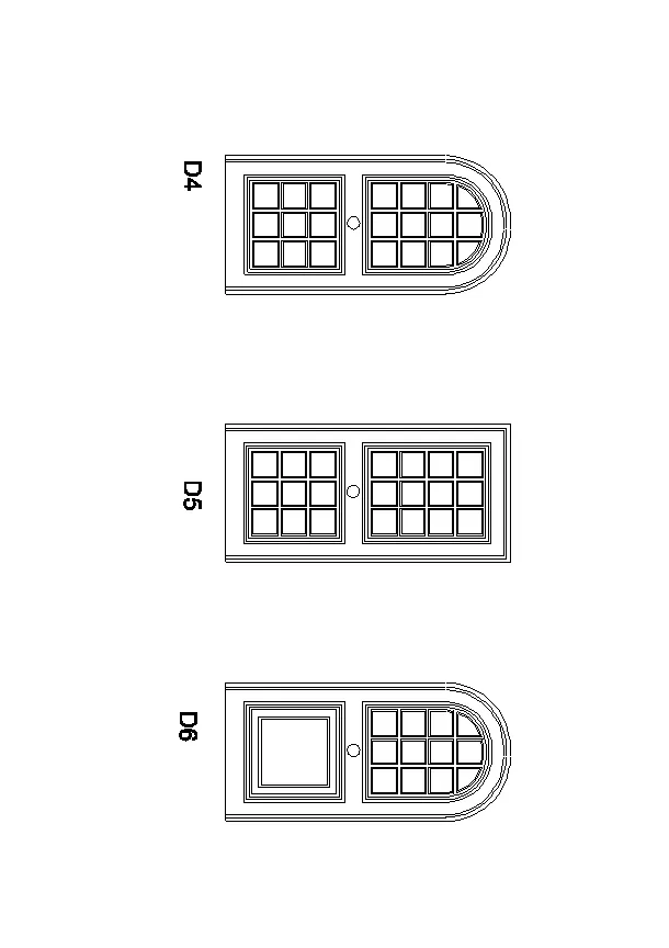
- Here, the door name is D1, D2, D3, D4, D5 and D6
- D4, D5 and D6 is refer the size of door 2
- Here, using the command of Arc in the top of the door panel and Offset the arc by through method
- And using the Trim command to delete the excessive line in the arc
- Finally Copy command to copy the door 6 and delete the bottom panels
- Atlast using the snipping tool to take the screenshot of templates
- The shortcut is Windoes key+Shift+S
- Finally upload the figures for reference
Result:
The creation of door type for residential building as a block by using the AutoCAD 2023 software
5. Create each shape as a block as shown in the Figure. Save the block and insert them on the table as shown in the Figure.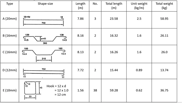
Aim:
To create each shape as a block as shown in the figure by using the AutoCAD software
Introduction:
Create each shape as a block as shown in the Figure. Save the block and insert them on the table as shown in the Figure.
Procedure:
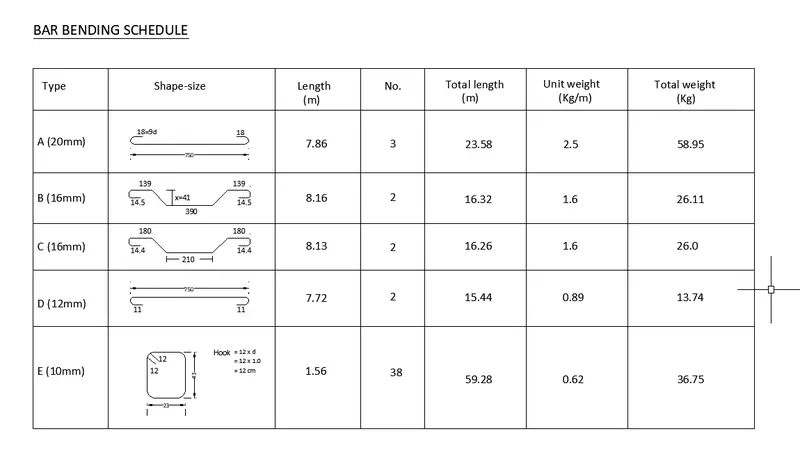
- Here, using the Line command for draw the steel shape and size
- And draw the hook using the Fillet - Radius command to bend the line and give the radius of the fillet
- Then, draw the table using the Line command
- Text the MText command to give the title and the content of the table
- Scale the text using the Scale command
- This table is called bar bending schedule (BBS)
- It represents the quantity of the steel required in the site
Result:
The creation of each shape as a block as shown in the figure is drawn by using the AutoCAD 2023 software