Creating Bar Bending schedule, Different Door types, and Creation of standard drawing templates using AutoCad
- Aim: To create-
- Template, inserting text and attributes.
- Doors of warehouse and placing it in blocks.
- Electrical legend and making it blocks.
- Different types of door for residential project.
- Drawing bars, making it as block and making it as a table as bar bending schedule.
- Procedure:
- Commands used-
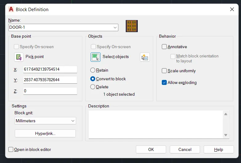
- Block- To make different elements into a single entity for easiness for work. Command "B". Block definition dialogue box appears. Create a name for block- specify the base point (any point of the object) - select the object - the block is created.
- We can pick a point or we can specify on screen or give the coordinates..
- After selecting objects there are options:
- Retain: the object will be retained as it is and block will be created.
- Convert to block: the object is converted into block.
- Delete: The object will be deleted from the screen but block will be created and we can insert it whenever needed.
- We can give scale uniformly, so that the block will be scaled in same scale in X and Y.
- If we select allow exploding, the block can be exploded when required.
- Insert- To insert a block. Command "I" - we can select the required block created and insert it.
- Attributes- Command "ATT" - attribute define dialogue box appears - give tag line, prompt and default value - give the mode - constant, lock, etc., alignment of text.
- Field- To create text along with block. (text and block are connected). From insert tab - click on the field - click on object - select block - select the name of the block to be appeared - select the text style and click on OK.
- Rectangle- Command "REC" - click on dimension in command prompt and give the width and height.
- Line- Command "L"
- Text- Command "T" - enter the text box, give the height and style, then type the required text.
- Array- To repeat the objects in rows and columns (rectangular array). Command "ARR" - select the object to be repeated - select rectangular - enter the number of rows, columns and spacing etc.
- Mirror- Command "MI"
- Copy- Command "CO"
- Offset- Command "O"
1. Aim: Creating templates, inserting text and attributes
- Custom1_titleblock
- Custom2_titleblock
- Procedure:
a. Custom1_titleblock
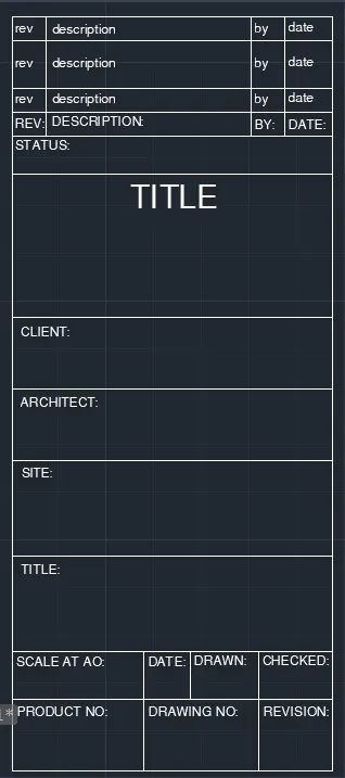
- Create a rectangleof size 66.63mm and 158mm
- Divide it with line for the text box into columns
- For rows, take offset of 5,10,5,558,30,15,15,20,10,15 mm.
- By multiline text type rev, description, by, date on the first row by text height 2.5 and style - Times New Roman.
- As it is repeated in the other two rows, take array give column as 1, row as 3, and spacing between rows as 7.
- Again use multiline text and type the required text in capitals with text height 1.5 and style as Times New Romans.
- Status:
- Title of Project:
- Client:
- Architect:
- Site:
- Scale, date, drawn by, checked by:
- Project no., drawing no., revision:
- These are items we have to provide in the title block.
- Creating Block:
- Command "B" - block definition dialogue box appears - give name as "Custom1_titleblock" - select pick point and select a point in the table (corner point) - select the object - select the whole table including the text.
- Select the convert to block option.
- Give scale uniformly and tick allow exploding.
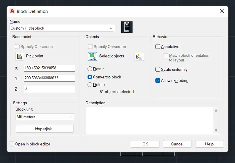
- As we have selected, convert to block option, the object itself is converted to block and we do not have to insert it again.
b. Custom2_titleblock
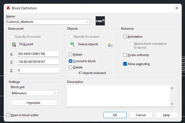
- Draw rectangle of 252 x 46 mm
- With lines divide according to the required rows and columns.
- With the use of multiline text with height 2.5 insert the following.
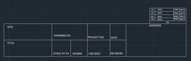
- Create a small rectangle at the right corner, explode it, create rows and columns.
- By attributes, create the text inside it.
- Command "ATT" - attribute definition dialogue box appears.
- Insert the tag line:
- Tag: Tag will be visible as what we give the block while creating the block.
- Prompt: Question we need to add what we need to enter.
- Default: The value shown in drawing after making it as a block.
- We have selected lock position here.
- For eg: In the first row 1st column "C" is the text to be displayed. Command "ATT"
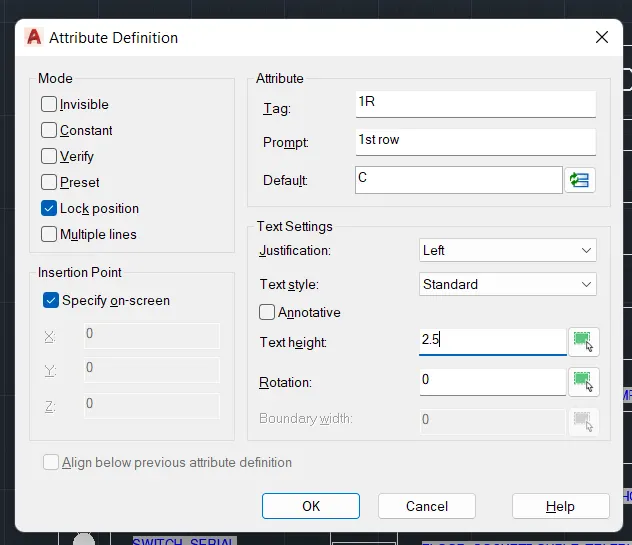
- Place the tag line on the place we need to. Here 1st row 1st column of the box is created.
- Create attributes similarly for the rest of the text.
- The attributes created are:
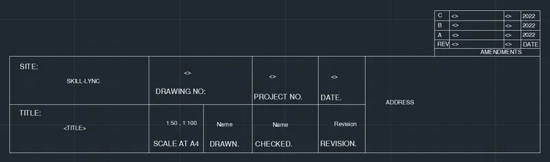
- RESULT:
- The Custom1_titleblock is created:
- Custom2_titleblock
- Aim: Creating doors for warehouse and placing it in blocks:
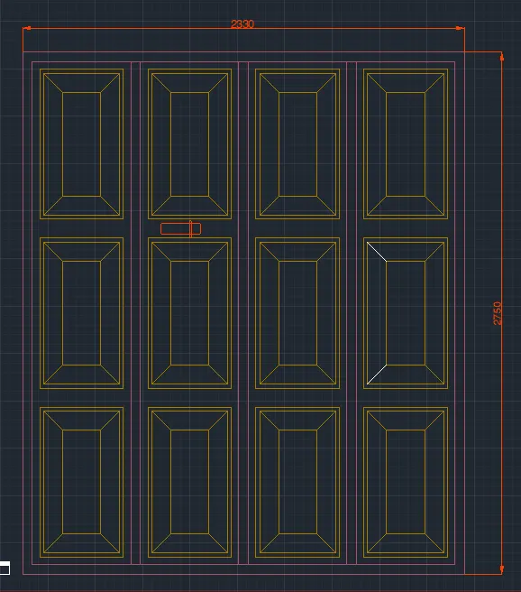
- Door1 - 2330 x 2750 mm
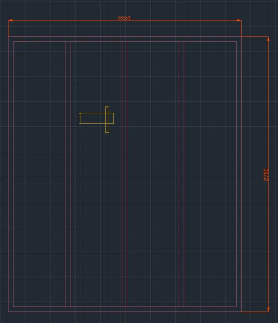
- Door2 - 2330 x 2750 mm
- Procedure:
a. Door1 - 2330 x 2750 mm
- Create a rectangle of size 2330 x 2750 mm.
- Offset 50mm as a frame. 90mm for the left side.
- Explode the rectangle.
- By using "DIV" divide the top line into 4 segments.
- From the division point, draw lines vertically to divide them into shutters.
- Offset 25mm on both sides for the thickness, and delete the center line.
- Create a rectangle to show the panels.
- Offset 20mm from the 1st rectangle and offset 100mm from the 2nd rectangle.
- Draw lines joining the corners of the outside and inside the rectangle.
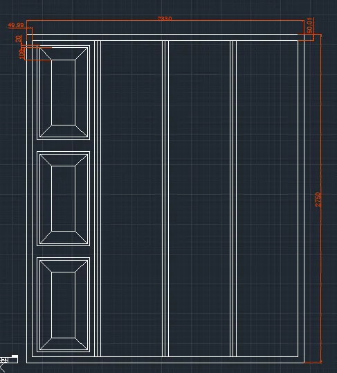
- Create the panel as a block, so that it is easy to copy.
- Array the panels, taking rectangular array, rows 3 with in-between distance 900mm and column 4 with in-between distance 567mm.
- Create lock by rectangle command, and fillet the corners with radius 5mm.
- Layer is created and all the objects are kept in different layers.
- Creating block:
- Command "B" - give name as DOOR 1 - pick point - select corner point - select object - select the whole object - OK.
- Select scale uniformly and allow exploding.
b. Door2 - 2330 x 2750 mm
- Create a rectangle of size 2330 x 2750 mm.
- Offset 50mm as a frame. 90 mm for the left side.
- Explode the rectangle.
- By using "DIV" divide the top line into 4 segments.
- From the division point, draw lines vertically to divide them into shutters.
- To make the points visible, Command "DDTYPE" and select the style of point.
- Offset 25mm on both sides for the thickness, and delete the center line.
- Create a lock by a rectangle drawn on opposite sides and fillet the corners with a radius of 5mm.
- Make layers and insert lock, frame in different layers.
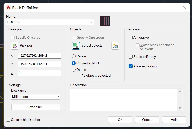
- Create it as a block "DOOR-2" - pick a corner point - select the whole door - tick the box of scale uniformly - explode.
- RESULT:
- DOOR-1
- DOOR-2
3. Aim: To create the electrical legend
- Create each electrical symbols
- Creating them as block
- Arranging them in legends
- Procedure:
a. Creating electrical symbols
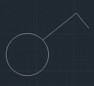
i. Single gang switch: Draw a circle of radius 64mm and with line draw an inclined line vertical and horizontal line perpendicular to the inclined as required.
ii. Double gang switch: Draw a circle and draw two horizontal lines and a vertical incline line.
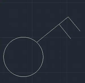
iii. Triple gang switch: Draw circle, 1 vertical incline line
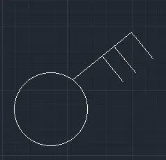
iv. Single two-way switch: Draw same as single gang switch and with donut command give internal dia as zero and for external diameter select in the circle.
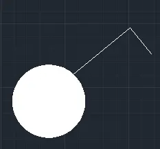
v. Double two-way switch: Draw the same double gang switch and create donut.
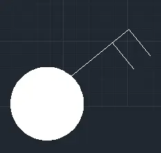
vi. Triple two-way switch: Draw same as triple gang switch and create a donut.
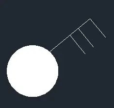
vii. Switch cross: Create a circle and donut inside and with line command draw an inclined vertical and perpendicular horizontal. Mirror the line in both direction.

viii. Switch serial: Copy the switch cross and delete two bottom lines, remove the donut also.

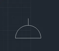
ix. Single socket: Create a circle, divide it into half and draw a line at the top.
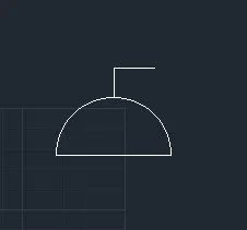
x. Single socket for the lamp: From the single socket, draw a horizontal line perpendicular to the vertical.
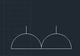
xi. Double socket: Draw the single socket and copy it to create the same and place it using snap-on.
xii. Floor socket single: Draw a rectangle surrounding a single socket

xiii. Floor single socket for the lamp: Draw a rectangle surrounding a single socket for the lamp.
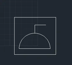
xiv. Floor socket double: Create two single sockets and place a rectangle surrounding them.
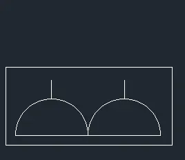
xv. Floor socket single telephone: Draw a single socket, a triangle and surrounded by a rectangle.
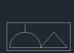
xvi. Floor socket double, telephone: Draw two single socket and a triangle surrounded by a rectangle.
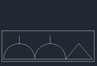
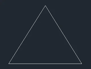
xvii. Telephone socket: Draw a triangle.
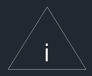
xviii. Internet socket: Insert text "i" in the triangle.
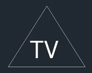
xix. TV socket: Insert text "TV" in the triangle.
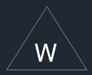
xx. Weatherproof socket: Insert text "w" in the triangle.
xxi. Dect base section: Draw a rectangle - select the bottom grip point - select add vertex - then pull the vertex to create a bend, with line draw the lines.
xxii. Wall bracket: With rectangle draw the base, create a circle, draw a line connecting the rectangle and circle, draw a cross line inside the circle.
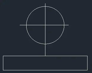
xxiii. Picture lamp: Draw two rectangles connected by a line.
b. Creating them as block:
- Command "B" give name as single gang switch - pick a point - select object (created single_gang_switch) - tick scale uniformly and allow exploding options.
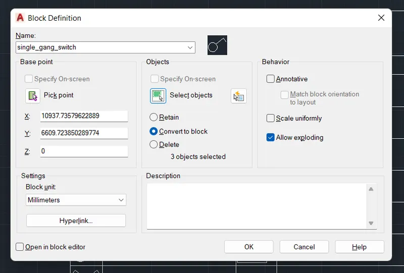
- Similarly, define each one of them as a block giving the respective names.
- 23 blocks will be created
- single_gang_switch
- double_gang_switch
- triple_gang_switch
- single_twoway_switch
- double_twoway_switch
- triple_twoway_switch
- switch_cross
- switch_serial
- single_socket
- single_socket_forlamp
- double_socket
- Floor_socketsingle
- Floor_singlesocket_forlamp
- Floor_socketdouble
- Floor_socketsingle_telephone
- Floor_socketdouble_telephone
- Telephone_socket
- Internet_socket
- TV_socket
- Weatherproof_socket
- Dect_basesection
- Wall_bracket
- Picture_lamp
c. Creating and arranging them in layers:
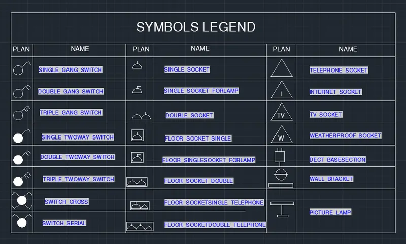
- First create a rectangular table having 10rows and 6 columns.
- Place each of the blocks in the respective rows and columns.
- To enter text with the block from the insert tab - select field - select object - select block.
- eg: for single_gang_switch - select from the field - select uppercase in format.
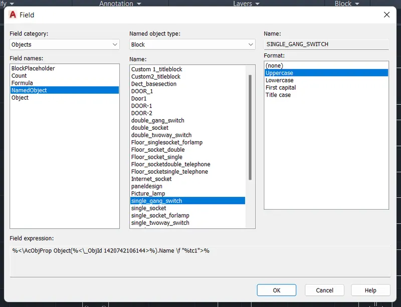
- Place the text in the respective rows and give the text height to 125
- Similarly, place all the titles inside the legend.
- RESULT:
4. Aim: To draw the doors of the residential project and create them as blocks.
- D1
- D2
- D3
- D4
- D5
- D6
- Procedure:
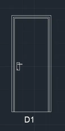
a. D1 - 2'10" x 6'11"
- Draw rectangle with dimension 2'10" and 6"11"
- Draw offset 1.5" for frame.
- Draw offset 1" for the shutter.
- Draw lock by two rectangles perpendicular to each other and fillet the corners with a radius of 0.1" and circle.
- Write text with "MTEXT" - "D1"
- Create it as block "B" - give name as "type-D1" - pick a corner point - select the object - create as block.
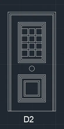
a. D2 - 3'4" x 6'11"
- Draw rectangle with dimension 3'4" and 6"11"
- Draw offset 1.5" for frame.
- Draw offset 1" for the shutter.
- Draw rectangle for panel 1'11" and 2'9.1", then offset 1" two times.
- Draw a rectangle of 5.4" x 5.7" and offset at 0.3"
- Copy it with copy command "co" - select mode - select the rectangle - select array - enter number of array as 3 and place it as required.
- Copy the 3 rectangles to 4 rows.
- For the second panel draw a rectangle of 1'11" x 2'0.6" and offset 1" 3 times.
- Draw another rectangle inside this of 1'0.8" x 1'1.2" and offset at 1".
- Draw a lock with circle in between the two panels.
- Write text with "MTEXT" - "D2"
- Create it as block "B" - give name as "type-D2" - pick a corner point - select the object - create as block.
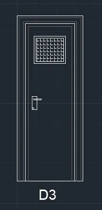
c. D3 - 2'9" x 6'11"
- Draw rectangle with dimension 2'10" x 6"11"
- Draw offset 1" for architrave thickness, 2" offset for frame, 1" thickness.
- Draw offset 1.5" for the shutter.
- Draw a rectangle at the top for ventilation 1'3" x 9.3", and give offset 1" for thickness.
- Hatch inside the rectangle.
- Draw lock by two rectangles perpendicular to each other and fillet the corners with a radius of 0.1" and circle.
- Write text with "MTEXT" - "D3"
- Create it as block "B" - give name as "type-D3" - pick a corner point - select the object - create as a block.
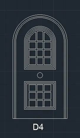
d. D4 - 3'9" x 6'11"
- Draw rectangle with dimension 3'10" x 6"11"
- Explode it and create an arc with 2 point method with both point as the endpoints.
- Offset the arc and the line with 1.5" and then 1".
- Offset 8" from arc and rectangle for panel and divide it into two.
- Take 1" offset 2 times to show the thickness on top figure and bottom rectangle.
- Create rectangles inside the panel.
- For lock, create a circle.
- Write text with "MTEXT" - "D4"
- Create it as block "B" - give name as "type-D4" - pick a corner point - select the object - create as a block.
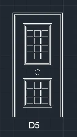
e. D5 - 3'5" x 6'11"
- Draw rectangle with dimension 3'5" x 6"11"
- Offset 1.5" for frame.
- Offset 1" as shutter thickness.
- Create another rectangle inside with offset 4.4".
- Create another rectangle on the bottom 2'2.9" x 2'2.6"
- Offset 1" two times for both rectangles.
- Create rectangles inside for panels with an offset 0.5"
- Copy it for 3 columns and 4 rows.
- Similarly, copy it in bottom rectangle for 3 rows and 3 columns.
- Write text with "MTEXT" - "D5"
- Create it as block "B" - give name as "type-D5" - pick a corner point - select the object - create as a block.
f. D6 - 3'5" x 7'11.6"
- Draw rectangle with dimension 3'5" x 7"11.6"
- Explode it and create an arc with 2 point method with both point as the endpoints.
- Offset the arc and the line with 1.5" and then 1 for frame".
- Offset 8" from arc and rectangle for panel and divide it into two.
- Take 1" offset 2 times to show the thickness on top figure and bottom rectangle.
- Create rectangles inside the top panel, 3 row and 4 columns.
- For bottom panel, offset the rectangles by 1" 3 times and 3.3" and again 1"
- For lock, create a circle.
- Write text with "MTEXT" - "D6"
- Create it as block "B" - give name as "type-D6" - pick a corner point - select the object - create as a block.
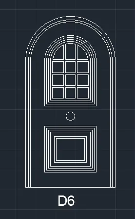
- RESULT: The doors are created and are made into blocks.
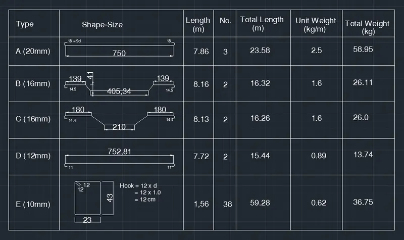
5. Aim: To create bar bending schedule and insert it as block.
- Drawing each shape
- Creating it as block
- Inserting it in table as Bar Bending Schedule.
- Procedure:
a. Drawing each shape
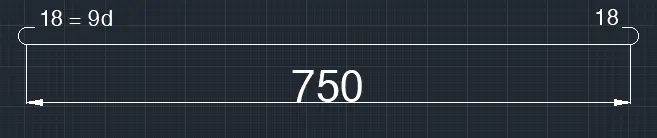
- A - 20mm
- Draw a line of 750cm for straight bar.
- Create arc for the bend. Create on one side and mirror it on another side.
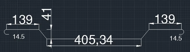
- B - 16mm
- Draw line of 300mm for straight bar.
- Draw vertical line of 41cm and extend a horizontal line and draw a line inclined at 45 degree from the base of vertical line up to horizontal line.
- Trim off the unwanted lines.
- Copy the same on the other side.
- Draw a horizontal line of 139cm and copy it on the other side.
- Draw bend with arc and mirror the same on the other side.
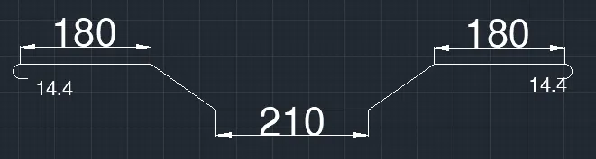
- C-16mm
- Draw a line of 210cm.
- Draw vertical line of 41cm and extend a horizontal line and draw a line inclined at 45 degree from the base of vertical line up to horizontal line.
- Trim off the unwanted lines.
- Copy the same on the other side.
- Draw a horizontal line of 180cm and copy it in other side.
- Draw bend with arc and mirror the same on the other side.
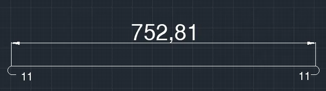
- D - 12mm
- Draw a line of 750cm for straight bar.
- Draw an arc downwards.
- Copy it on the other side.
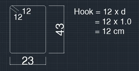
- E - 10mm
- Draw a rectangle of 23cm and 43cm.
- Fillet the corner with fillet radius 5cm.
- Draw two line of 12cm
b. Creating each of them as block
- Command "B" - give name as A - pick a point - select the object - select delete - tick box of scale uniformly and explode all.
- Similarly, create 5 blocks : A,B,C,D,E and insert each of the bars as blocks.
c. Inserting it in table
- Create a table with rectangle and divide it into 6 rows and 7 columns.
- With multiline text entry type, shape size, length, no., total length, unit weight, total weight, and all other text.
- By command "i" insert each of the block in respective columns.
- RESULT:
- RESULT:
- Template is drawn and text and attributes are inserted.
- Doors of warehouse are drawn and placed it in blocks.
- Electrical legend are created and it is made into blocks.
- Different types of doors for residential project are drawn and are placed in blocks.
- Bars are drawn and made it as blocks and inserted it in table as bar bending schedule.