Creating Bar Bending schedule, Different Door types, and Creation of standard drawing templates using AutoCad
ANSWERS:
DRAWING TEMPLATE
AIM : To Create a Drawing Templates using primary tools such as line, rectangle etc from AutoCad
Introduction : Drawing template gives the Clear Basic idea of the particular sheet of the drawing, Template is Done using tools such as Line, Rectangle,offset, Mtext, Erase, Extend,etc., Detailed Step by step Procedure is Given with Results.
Procedure :
Go to START MENU, select AutoCAD 2022.
• In the Command line type in: STARTUP [ENTER]
• Enter new value of startup: 1
• Go to Application Menu and select New
• In the 'Create New Drawing' dialog box, we do the Advanced Setup and select the 'Decimal' unit of measurement and select precision as 0.0
• Set the limits by entering LIMITS in the Command tab. The lower-left corner is specified as 0,0 and the upper-right corner is specified as 5000,5000
• Enter 'UNITS' command in the command tab.
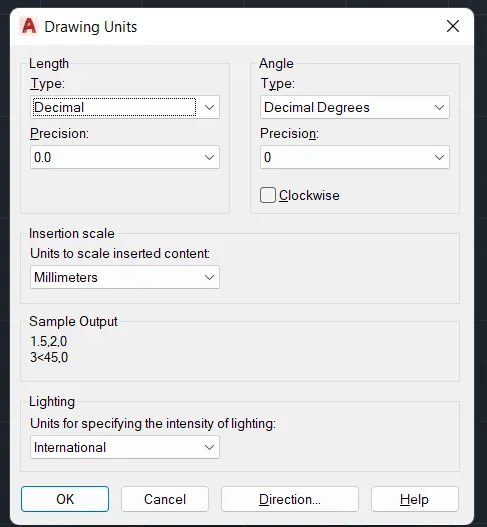
• In the Drawing Units dialog box, select 'Decimal' in Type; 0,0 in Precision; and 'Millimeters' in Insertion scale.
• Click on 'OK'.
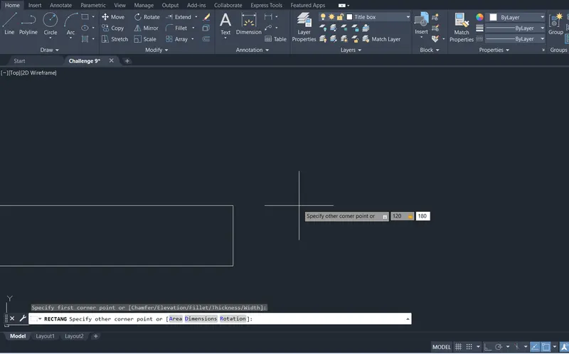
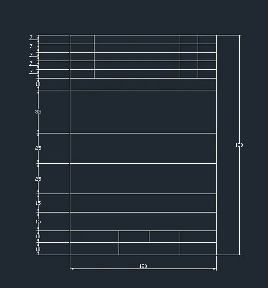
Rectangle: Create a Rectangle of 120 x 180
Explode: Select and Explode the Rectangle
Offset: Create the offset of 7mm in 5 times in Downwaed direction from top
Repeat offset of 10,35,25,25,15,15,10,10 from previously offsetted lines
Create offsets of 30,50,20,20 from Left
LAYER: Dimensions
DIMLENIAR: Select and Place the Desired Dimensions, Represent all the Dimensions
DIMSTY: Set Arrow size 25, Text Height 15, Precision to 0
DIMCONTINUE: Create Remaining Dimensions
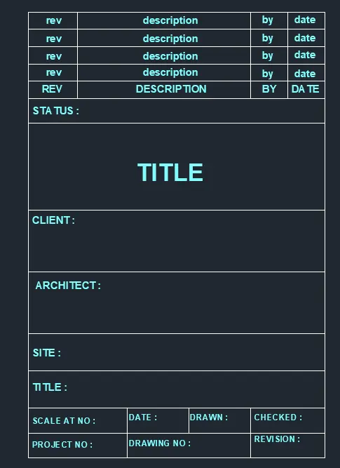
MTEXT: Create a Text Box and Enter the sample text, Copy and Paste multiple in Desired Position and desired angle with Desired Size
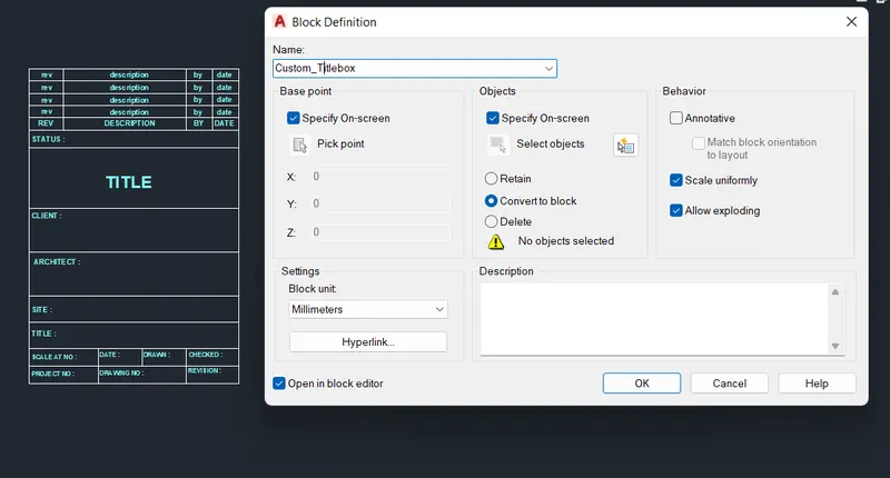
Block Edit : Select Block editor and Specify the name as "Custom_Title box"
Base point as Specify on screen
Objects as Specify on screen
check the "Convert to Block"
Click ok
Select the basepoint and objects and Close the blockeditor
Result:
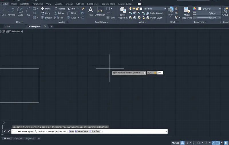
Rectangle: Specify 500,50
Explode: Select and Explode the rectangle
Offset: Create the Offset of 25 to devide the Rectagle at middle
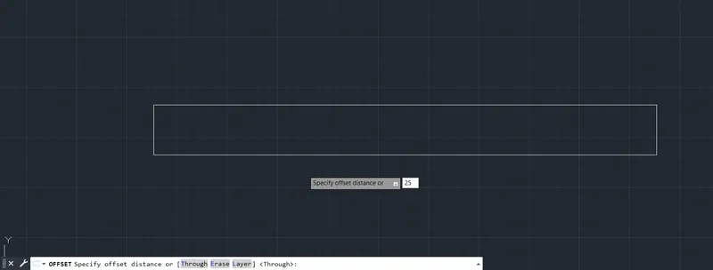
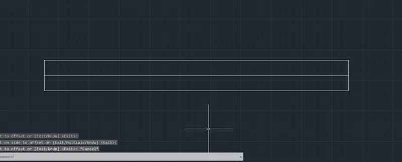
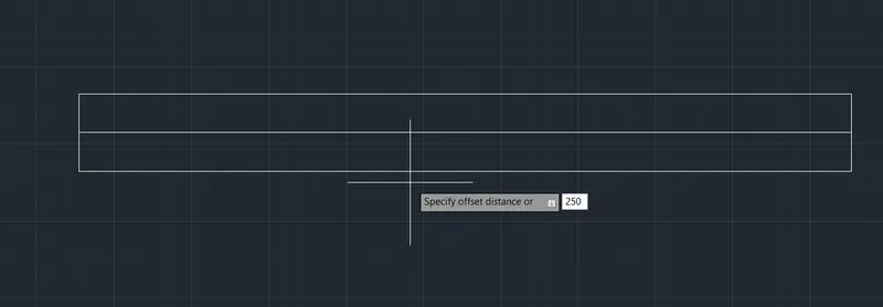
Offset : Create the Offset of 250 from left
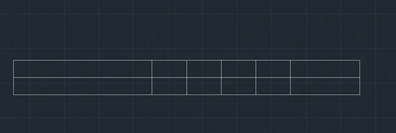
Repeat the offset of 40 in 4 times
Rectangle: Create a Rectangle of -75,50 from right top corner of previously created rectangle
Explode :Select and explode the rectangle
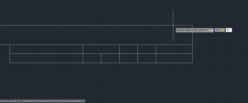
Offset : Create an offset of 10 in downward direction from top
specify 10,35,10 from left
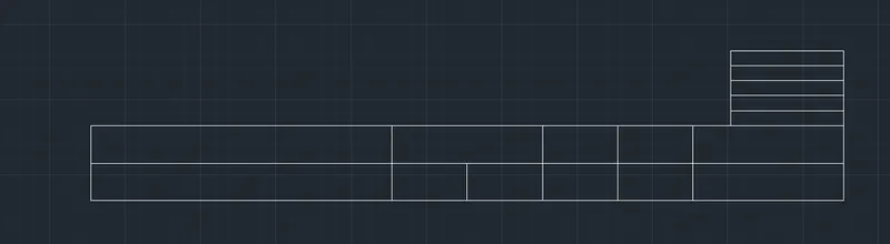
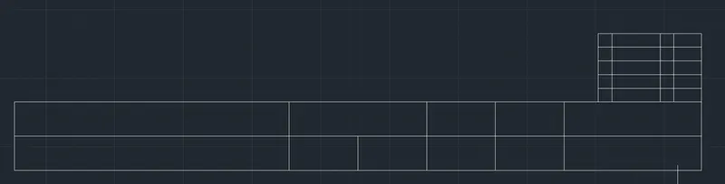
LAYER: Dimensions
DIMLENIAR: Select and Place the Desired Dimensions, Represent all the Dimensions
DIMSTY: Set Arrow size 25 Text Height 15, Precision to 0
DIMCONTINUE: Create Remaining Dimensions
MTEXT: Create a Text Box and Enter the sample text, Copy and Paste multiple in Desired Position and desired angle with Desired Size
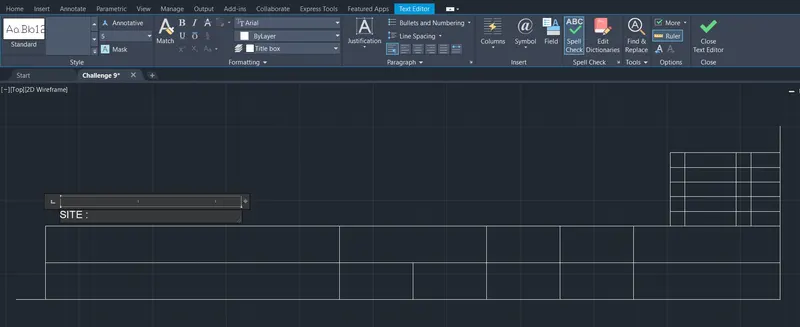
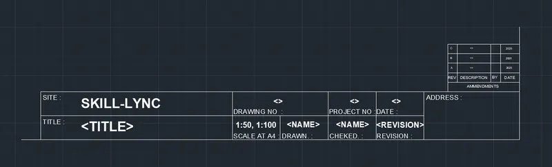
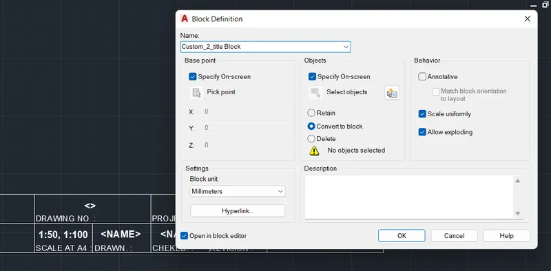
Block Edit : Select Block editor and Specify the name as "Custom_2_Title box"
Base point as Specify on screen
Objects as Specify on screen
check the "Convert to Block"
Click ok
Select the basepoint and objects and Close the blockeditor
Result :
DOOR:
AIM : To Create a Door blocks by using primary tools such as line, rectangle etc from AutoCad
Introduction : Door Template is Done using tools such as Line, Rectangle,offset, Mtext, Erase, Extend,etc., Detailed Step by step Procedure is Given with Results.
Procedure :
Go to START MENU, select AutoCAD 2022.
• In the Command line type in: STARTUP [ENTER]
• Enter new value of startup: 1
• Go to Application Menu and select New
• In the 'Create New Drawing' dialog box, we do the Advanced Setup and select the 'Decimal' unit of measurement and select precision as 0.0
• Set the limits by entering LIMITS in the Command tab. The lower-left corner is specified as 0,0 and the upper-right corner is specified as 5000,5000.
• Enter 'UNITS' command in the command tab.
• In the Drawing Units dialog box, select 'Decimal' in Type; 0,0 in Precision; and 'Millimeters' in Insertion scale.
• Click on 'OK'.
Rectangle: Specify the sizew of the Rectangle as 2500,3000
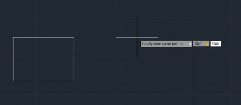
Explode: Select and Explode the Rectangle
Offset : Create the Internal offsets as shown in Figure
Specify the offset distance of 10,300,10,20 in inward direction
Trim: Select and Trim unwanted lines
Devide: Select and Devide total area in to 4 parts by selecting a top line
Line : Draw the lines to create 4 partitions
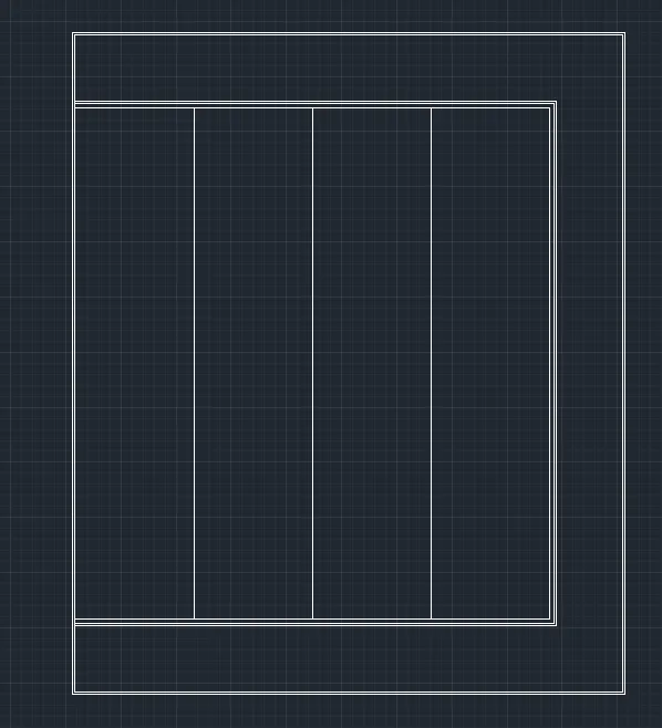
Now create a Inside panel for the door as shown in figure
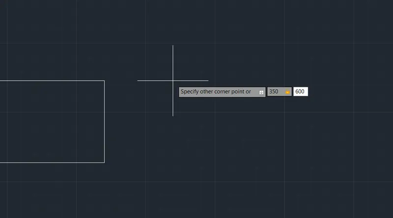
Rectangle: Specify 350,600
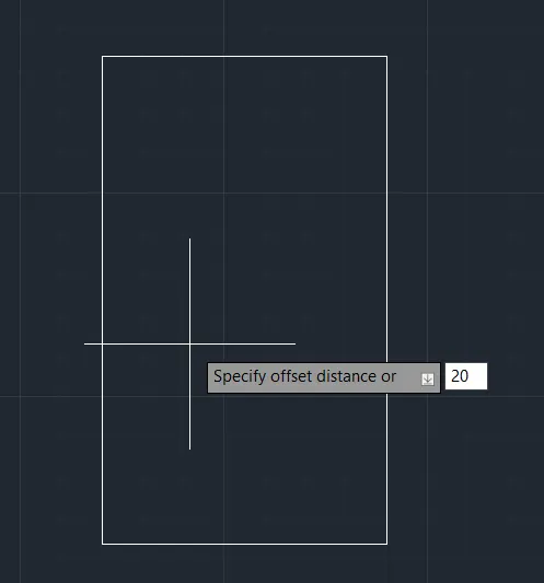
Offset : Specify 20mm and Drag inside
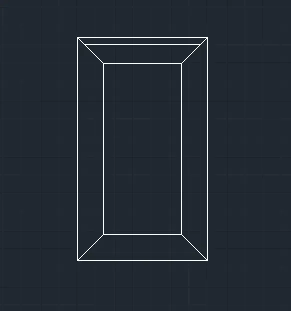
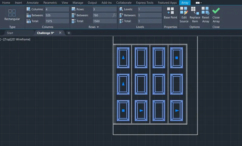
Array : Now Click on array specify 4 columns at 525 and 3 rows at 780 and Close array
Block Edit : Select Block editor and Specify the name as "Door1"
Base point as Specify on screen
Objects as Specify on screen
check the "Convert to Block"
Click ok
Select the basepoint and objects and Close the blockeditor
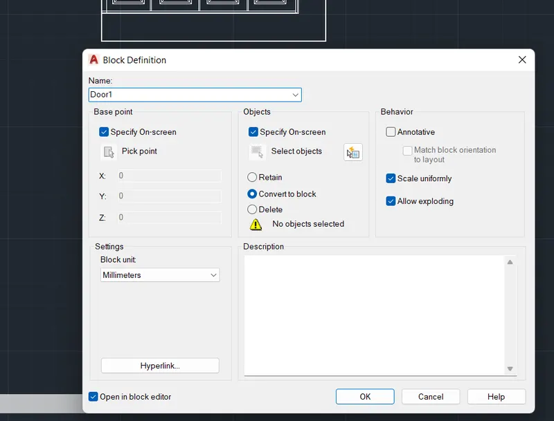
Result :
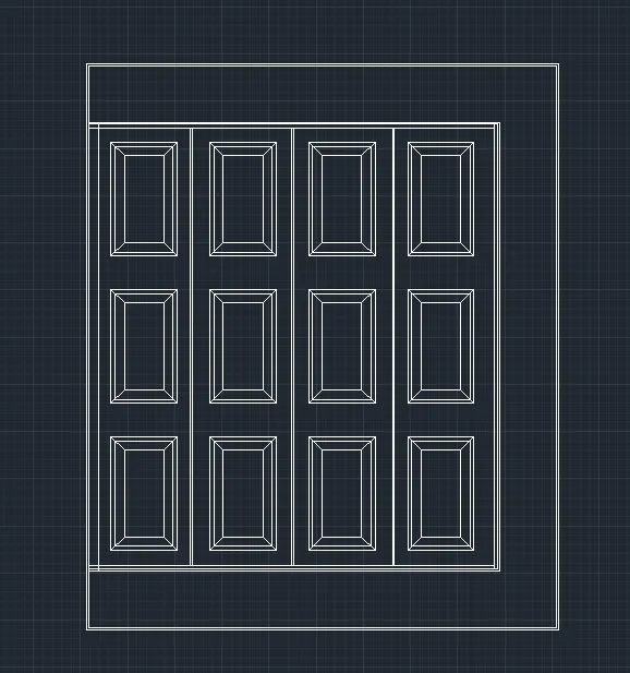
Copy : copy the Door1 created
Explode: select and explode the Block
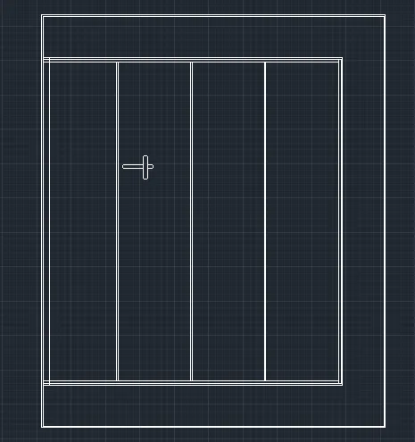
Trim: Remove all the Internal Panels
Block Edit : Select Block editor and Specify the name as "Door2"
Base point as Specify on screen
Objects as Specify on screen
check the "Convert to Block"
Click ok
Select the basepoint and objects and Close the blockeditor
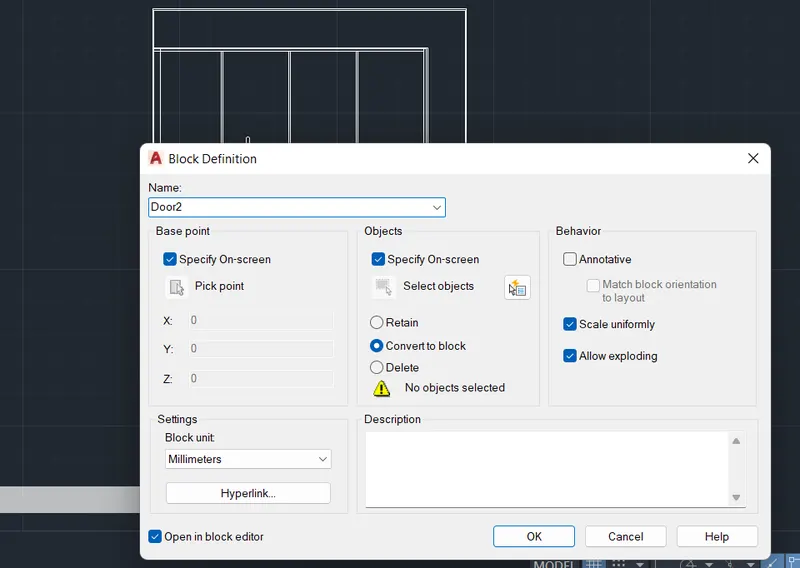
Result :
Aim: To create each symbol as a block and arranging them accordingly in the legend using AutoCAD.
Introduction: The given symbols are created in AutoCAD using primarily from basic tools such as Rectangle, Circle and Line tools. The procedure of drawing is explained in detail with diagrams of each step and the final result is given.
Procedure :
Go to START MENU, select AutoCAD 2022.
• In the Command line type in: STARTUP [ENTER]
• Enter new value of startup: 1
• Go to Application Menu and select New
• In the 'Create New Drawing' dialog box, we do the Advanced Setup and select the 'Decimal' unit of measurement and select precision as 0,0
• Set the limits by entering LIMITS in the Command tab. The lower-left corner is specified as 0,0 and the upper-right corner is specified as 10000,10000
• Enter 'UNITS' command in the command tab.
• In the Drawing Units dialog box, select 'Decimal' in Type; 0,0 in Precision; and 'Millimeters' in Insertion scale.
• Click on 'OK'.
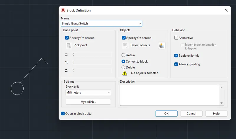
Circle : Specify the center and enter radius circle as radius 50.
Line : Draw an inclined line of lenght 100 from the circumference of the circle, and another line of length 50
Block Edit : Select Block editor and Specify the name as "Single Gang Switch"
Base point as Specify on screen
Objects as Specify on screen
check the "Convert to Block"
Click ok
Select the basepoint and objects and Close the blockeditor
Double Gang Switch :
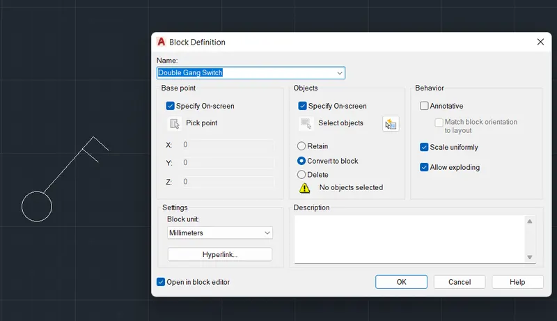
Circle : Specify the center and enter radius circle as radius 50
Line : Draw an inclined line of lenght 100 from the circumference of the circle, and another line of length 50
Offset : Specify an Offset of 30 and Create an offset beside the previously created line
Block Edit : Select Block editor and Specify the name as "Double Gang Switch"
Base point as Specify on screen
Objects as Specify on screen
check the "Convert to Block"
Click ok
Select the basepoint and objects and Close the blockeditor
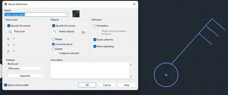
Copy : Select and Copy the Prviously created Block
Explode: Select and Explode the Block
Offset : Create an offset of 30 on previously created line
Block Edit : Select Block editor and Specify the name as "Single Gang Switch"
Base point as Specify on screen
Objects as Specify on screen
check the "Convert to Block"
Click ok
Select the basepoint and objects and Close the blockeditor
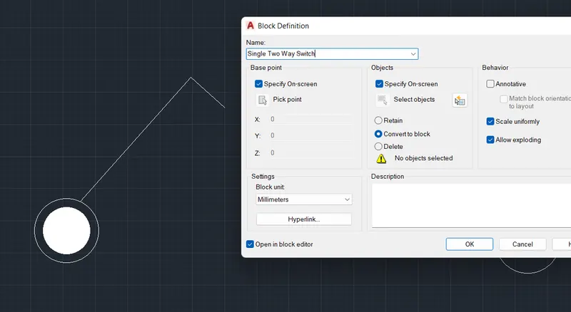
Copy : copy the Single gang switch
Explode: Select and Explode the Block
Offset : Create an offset of 20 on circle inwardly
Hatch : select Recently created circle Slect hatch pattern as solid and Hatch
Block Edit : Select Block editor and Specify the name as "Single Two way Switch"
Base point as Specify on screen
Objects as Specify on screen
check the "Convert to Block"
Click ok
Select the basepoint and objects and Close the blockeditor
Copy : copy the Single Two way Switch
Explode: Select and Explode the Block
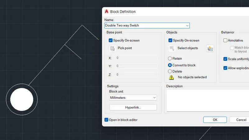
Offset : Create an offset of 30 on on a 50 mm line and offset it
Block Edit : Select Block editor and Specify the name as "Double Two way Switch"
Base point as Specify on screen
Objects as Specify on screen
check the "Convert to Block"
Click ok
Select the basepoint and objects and Close the blockeditor
Copy : copy the Double Two way Switch
Explode: Select and Explode the Block
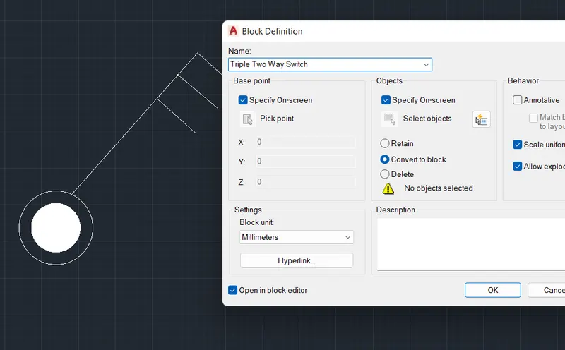
Offset : Create an offset of 30 on on a 50 mm line and offset it additionally
Block Edit : Select Block editor and Specify the name as "Triple two way Switch"
Base point as Specify on screen
Objects as Specify on screen
check the "Convert to Block"
Click ok
Select the basepoint and objects and Close the blockeditor
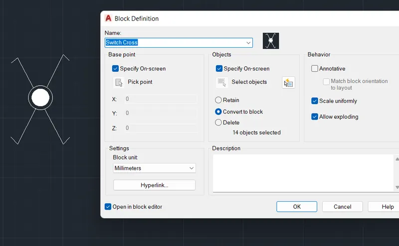
Switch Cross
Circle : Specify the center and enter radius circle as radius 50
Offset : Create an offset of 15 and Drag inside the triangle
Hatch : select Recently crated circle Slect hatch pattern as solid and Hatch
Line : Draw an inclined line of lenght 100 from the circumference of the circle, and another line of length 50
Copy : Select and Copy the line 3 times and Place ti Beside
Rotate : Rotate each line at desired angle
Move : Place it at desired Locations
Block Edit : Select Block editor and Specify the name as "Triple two way Switch"
Base point as Specify on screen
Objects as Specify on screen
check the "Convert to Block"
Click ok
Select the basepoint and objects and Close the blockeditor
Switch Serial :
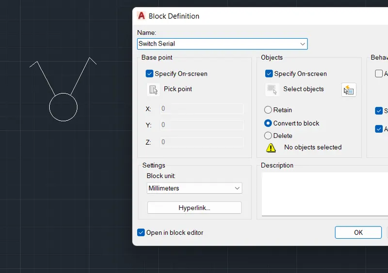
Copy : select and Copy the Switch cross
Explode: Selewct an Explode the Block
Trim : Select and Trim the bottom two lines of the object
Block Edit : Select Block editor and Specify the name as "Switch Serial"
Base point as Specify on screen
Objects as Specify on screen
check the "Convert to Block"
Click ok
Select the basepoint and objects and Close the blockeditor
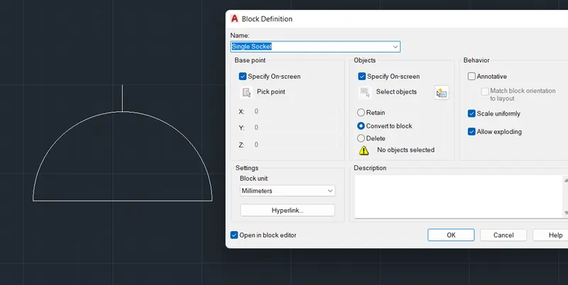
Singe Socket
Circle : Specify the center and enter radius circle as radius 50
Line : Create 2 lines horizontally and vertically bisecting the circle in center
Trim : Trim and cutoff the unwanted lines
Block Edit : Select Block editor and Specify the name as "Single Socket"
Base point as Specify on screen
Objects as Specify on screen
check the "Convert to Block"
Click ok
Select the basepoint and objects and Close the blockeditor
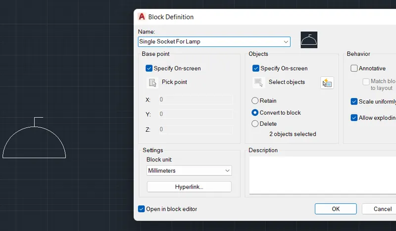
Single Socket For Lamp :
Copy : select and Copy the Single Socket
Explode: Selewct an Explode the Block
Line : Create a line of 20mm perpendicular to the previous line as shown in figure
Block Edit : Select Block editor and Specify the name as "Single Socket for lamp"
Base point as Specify on screen
Objects as Specify on screen
check the "Convert to Block"
Click ok
Select the basepoint and objects and Close the blockeditor
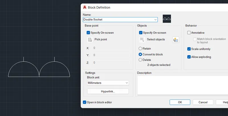
Double Socket :
Copy : select and Copy the Single Socket
Explode: Select an Explode the Block
Copy : Copy and Paste the same object beside the original object
Block Edit : Select Block editor and Specify the name as "Double Socket "
Base point as Specify on screen
Objects as Specify on screen
check the "Convert to Block"
Click ok
Select the basepoint and objects and Close the blockeditor
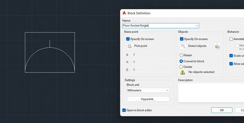
Floor Socket Single:
Copy : select and Copy the Single Socket
Explode: Select an Explode the Block
Rectangle : Create a Rectangle Around the object
Block Edit : Select Block editor and Specify the name as "Floor Socket Single"
Base point as Specify on screen
Objects as Specify on screen
check the "Convert to Block"
Click ok
Select the basepoint and objects and Close the blockeditor
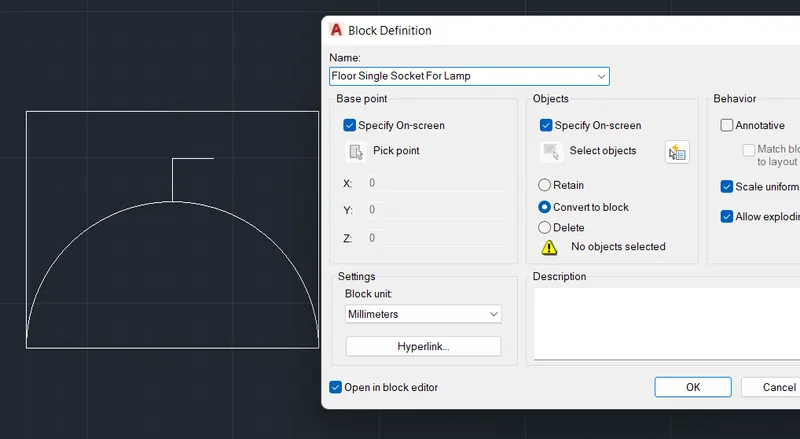
Single Socket for Lamp :
Copy : select and Copy the floor Socket single
Explode: Select an Explode the Block
Rectangle : Create a Rectangle Around the object
Block Edit : Select Block editor and Specify the name as "Floor single Socket for Lamp"
Base point as Specify on screen
Objects as Specify on screen
check the "Convert to Block"
Click ok
Select the basepoint and objects and Close the blockeditor
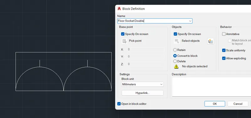
Floor Socket Double:
Copy : select and Copy the Double Socket
Explode: Select an Explode the Block
Rectangle : Create a Rectangle Around the object
Block Edit : Select Block editor and Specify the name as "Floor Socket Double"
Base point as Specify on screen
Objects as Specify on screen
check the "Convert to Block"
Click ok
Select the basepoint and objects and Close the blockeditor
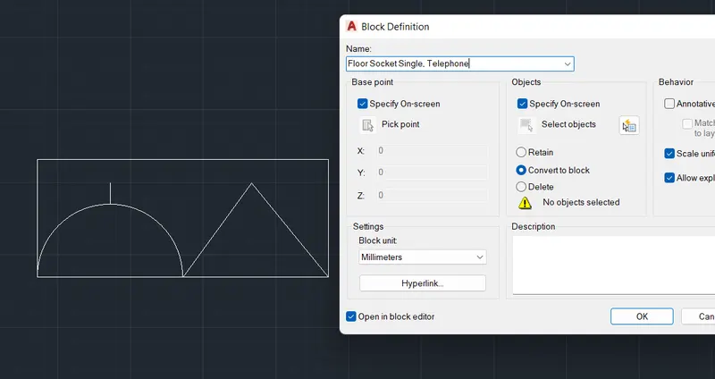
Floor Socket Single Telephone:
Copy : select and Copy the Floor Socket Double
Explode: Select an Explode the Block
Trim : Select and Trim the Second Object
Line : Create a Triangle as Shown in Figure
Block Edit : Select Block editor and Specify the name as "Floor Socket Single Telephone"
Base point as Specify on screen
Objects as Specify on screen
check the "Convert to Block"
Click ok
Select the basepoint and objects and Close the blockeditor
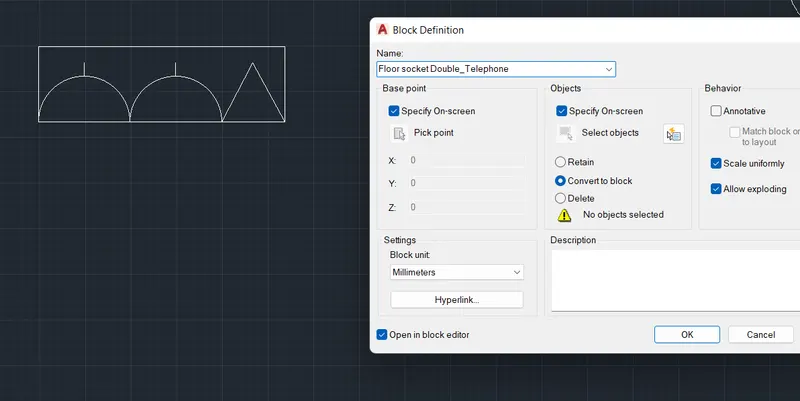
Floor Socket Double Telephone:
Copy : select and Copy the Floor socket Double
Explode: Select an Explode the Block
Trim : Select and Trim outer Rectangle
Line: Create a Triangle as shown in figure
Rectangle : Create a Rectangle Around the object
Block Edit : Select Block editor and Specify the name as "Floor Socket Double_Telephone"
Base point as Specify on screen
Objects as Specify on screen
check the "Convert to Block"
Click ok
Select the basepoint and objects and Close the blockeditor
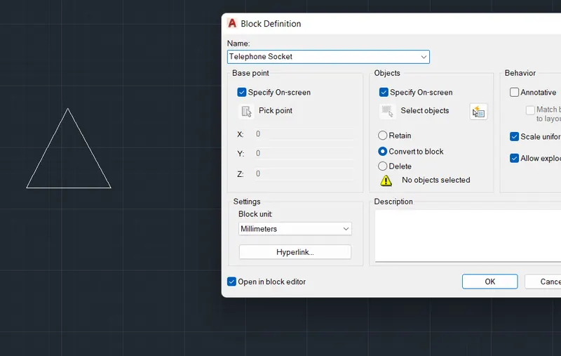
TelePhone Socket :
Line: Create a Line of Length 100,
Specify Next point as 100<120
Press "C" to close the Line
Block Edit : Select Block editor and Specify the name as "Telephone Socket"
Base point as Specify on screen
Objects as Specify on screen
check the "Convert to Block"
Click ok
Select the basepoint and objects and Close the blockeditor
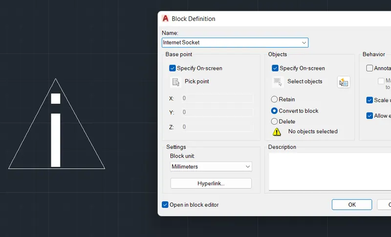
Internet Socket:
Copy : Select and Copy Telephone Socket
Explode: Select and Explode the Object
Mtext : create a Text box and specify font as "Arial" Bold, Text height as 25
Block Edit : Select Block editor and Specify the name as "Internet Socket"
Base point as Specify on screen
Objects as Specify on screen
check the "Convert to Block"
Click ok
Select the basepoint and objects and Close the blockeditor
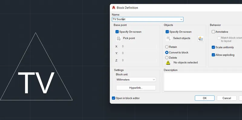
TV Socket :
Copy : Select and Copy TV Socket
Explode: Select and Explode the Object
Text : right click on Text and go to properties Change the Text as TV
Block Edit : Select Block editor and Specify the name as "TV Socket"
Base point as Specify on screen
Objects as Specify on screen
check the "Convert to Block"
Click ok
Select the basepoint and objects and Close the blockeditor
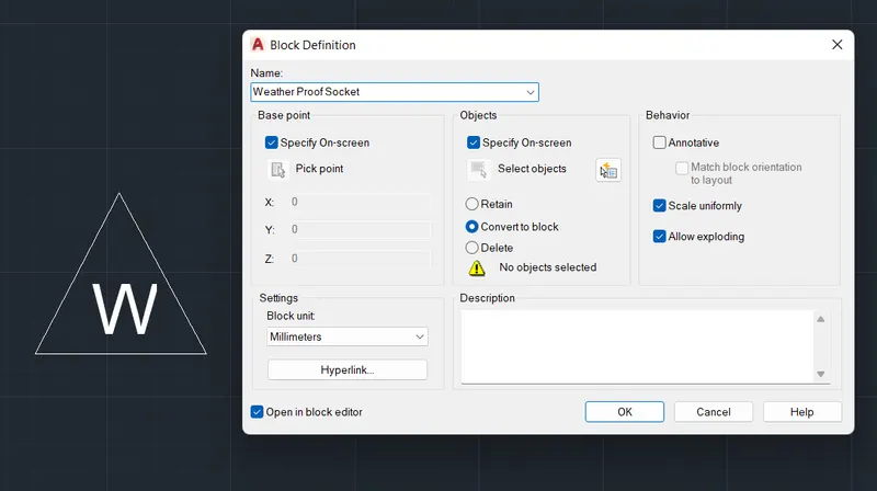
Weather proof Socket :
Copy : Select and Copy TV Socket
Explode: Select and Explode the Object
Text : right click on Text and go to properties Change the Text as W
Block Edit : Select Block editor and Specify the name as "Weather proof Socket"
Base point as Specify on screen
Objects as Specify on screen
check the "Convert to Block"
Click ok
Select the basepoint and objects and Close the blockeditor
Dect Base Station :
Pline : select the Polyline and Draw the Plug Head as shown in figure
Line : Draw the 2 pins Representing the Plug pins
Block Edit : Select Block editor and Specify the name as "DECT BASE STATION"
Base point as Specify on screen
Objects as Specify on screen
check the "Convert to Block"
Click ok
Select the basepoint and objects and Close the blockeditor

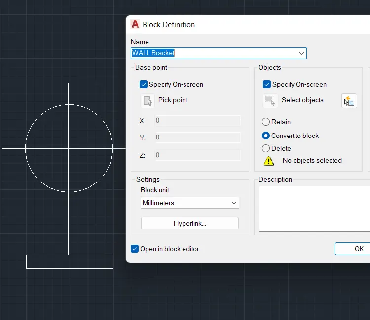
Wall Bracket:
Circle : Create a Circle of Radious 75
Line : Create horizontal and Vertical lines to bisect the Circle at Centre
Trim : Cut off the Unwanted Lines up to Required Length
Rectangle : Specify a Size of 200, 50 Place it at the Centre of the Cicle at the boittom as shown in figure
Block Edit : Select Block editor and Specify the name as "WALL Bracket "
Base point as Specify on screen
Objects as Specify on screen
check the "Convert to Block"
Click ok
Select the basepoint and objects and Close the blockeditor
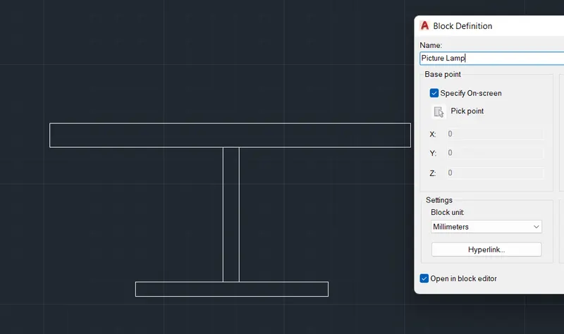
Rectangle : Create a Rectangle of Size 350, 50
Specify another as 50,150 and place iot at the bottom Centre of previous rectangle
Create another of size 120,50 and Place it at the bottom centre of previous Rectangle
Block Edit : Select Block editor and Specify the name as "Picture Lamp"
Base point as Specify on screen
Objects as Specify on screen
check the "Convert to Block"
Click ok
Select the basepoint and objects and Close the blockeditor
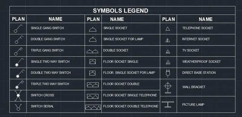
Rectangle :Create a Rectagle of 8000, 3800
Offset: Specify an Offset of 300 in downward direction and 400 from previously offseteed lines downward in seven times
Repeat offset of 600 from Left Hand side and Contiue by 2066, Repeat 600 & 2066 two more times to complete the table
Insert : Press "i" to invoke insert tool and add all The objects in the table as shown in Figure
Mtext : Create and place the text, Specify the Font as Arial, text Height as 25 for object names, 50 Bold for Row names, 75 Bold for Table Name
Copy : Copy the Created text and and Place it in required locations
Edit Text : Edit and Replace the required text in relevent Positions
Result :
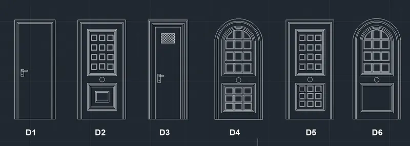
Aim: To create each the door types for residential building as a block using AutoCAD.
Introduction: The doors are created in AutoCAD using primarily the Rectangle, Circle and Line tools. The procedure of drawing is explained in detail with diagrams of each step and the final result is given.
Procedure :
Go to START MENU, select AutoCAD 2022.
• In the Command line type in: STARTUP [ENTER]
• Enter new value of startup: 1
• Go to Application Menu and select New
• In the 'Create New Drawing' dialog box, we do the Advanced Setup and select the 'Engineering' unit of measurement and select precision as 0'-0.0"
• Set the limits by entering LIMITS in the Command tab. The lower-left corner is specified as 0',0' and the upper-right corner is specified as 1000',1000'
• Enter 'UNITS' command in the command tab.
• In the Drawing Units dialog box, select 'Engineering' in Type; 0'0"— in Precision; and 'Inches' in Insertion scale.
• Click on 'OK'.
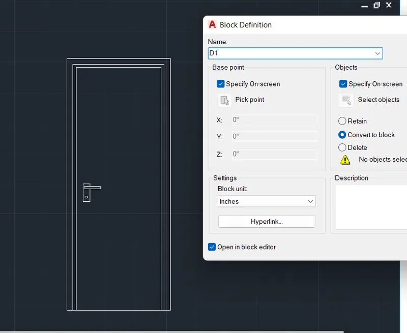
D1
Rectangle : specify size as 2'10",6'11"
Explode : select and Explode the Rectangle
Offset : specify 2" and click on inside, specify again 1" and click inside from previously created rectangle
Trim : Trim the offset lines on bottom of the line
Extend : Extend the offsetted lines upto the bottom
Rectangle : Create the rectangle and to make handle
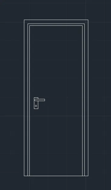
Block Edit : Select Block editor and Specify the name as "D1"
Base point as Specify on screen
Objects as Specify on screen
check the "Convert to Block"
Click ok
Select the basepoint and objects and Close the blockeditor
D2
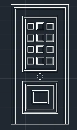
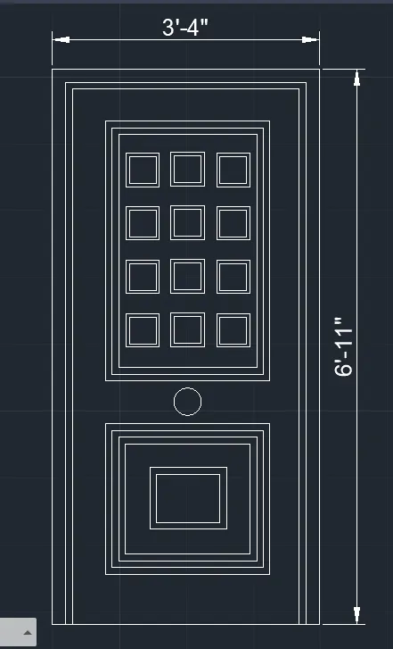
Specify the start point, Enter @3'4",6'11".
Explode: select and explode the rectangle
Offset :Specify an offset distance of 2", select the left side of the rectangle and then click on the inside.
Repeat offset, specify distance as 1", and then offset the three sides of the smaller inner rectangle.
Offset : offset the lines to create the pattern.
Trim : select and trim the unwanted lines
Rectangle : create and pattern as shown in figure
Dimleniar : Create and Place the Dimension lines as shown in figure
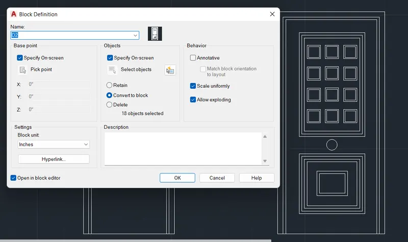
Block Edit : Select Block editor and Specify the name as "D2"
Base point as Specify on screen
Objects as Specify on screen
check the "Convert to Block"
Click ok
Select the basepoint and objects and Close the blockeditor
D3
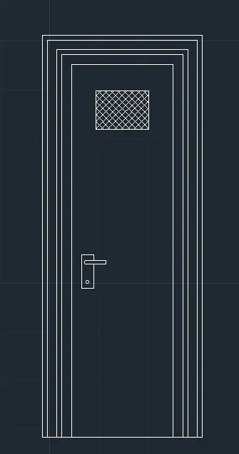
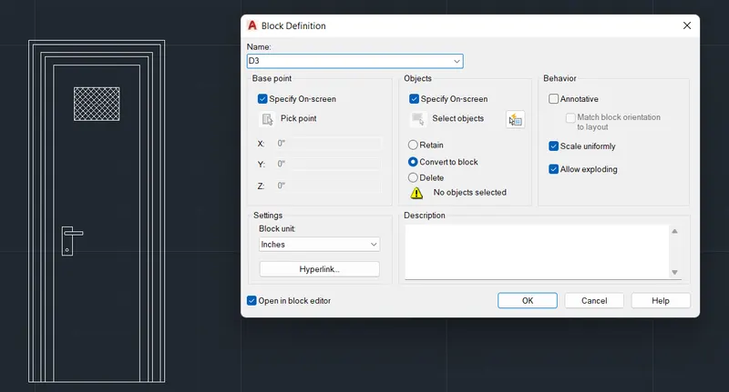
Block Edit : Select Block editor and Specify the name as "D3"
Base point as Specify on screen
Objects as Specify on screen
check the "Convert to Block"
Click ok
Select the basepoint and objects and Close the blockeditor
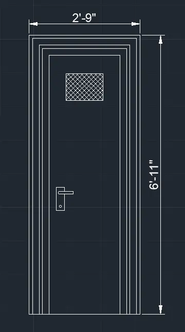
Dimleniar : Create and Place the Dimension lines as shown in figure
D4
Rectangle: Specify the start point, Enter @2'9",6'11".
Explode: Select the rectangle created and explode it.
Offset : Specify an offset distance of 2", select the left side of the rectangle and then click on the inside.
Repeat offset, specify distance as 1", and then offset the three sides of the smaller inner rectangle.
Rectangle: Specify the start point, Enter @11",8".
Hatch: select ANS137, pick point inside the rectangle.
Trim : Cutoff the Unwanted Lines
Line: Draw the door handl as shown in figure
Dimleniar : Create and Place the Dimension lines as shown in figure
Block Edit : Select Block editor and Specify the name as "D4"
Base point as Specify on screen
Objects as Specify on screen
check the "Convert to Block"
Click ok
Select the basepoint and objects and Close the blockeditor
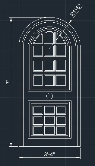
D5
Rectangle: Specify the start point, Enter @3'4",6'11".
Explode: Select the rectangle created and explode it.
Offset: Specify an offset distance of 2", select the left side of the rectangle and then click on the inside.
Repeat offset, specify distance as 1", and then offset the three sides of the smaller inner rectangle.
Offset the lines to create the Required pattern.
Trim : Trim the unwanted lines.
Line : Draw the door handle.
Dimleniar : Create and Place the Dimension lines as shown in figure
Block Edit : Select Block editor and Specify the name as "D5"
Base point as Specify on screen
Objects as Specify on screen
check the "Convert to Block"
Click ok
Select the basepoint and objects and Close the blockeditor
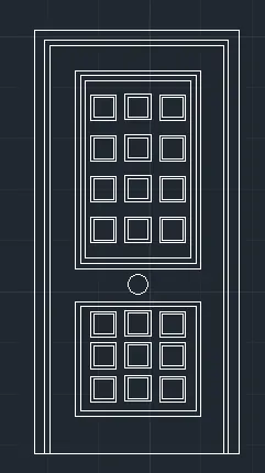
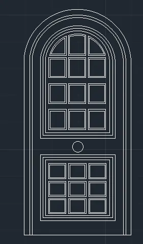
D6
Rectangle: Specify the start point, Enter @3'4",7'.
Explode: Select the rectangle created and explode it.
Offset :Specify an offset distance of 2", select the left side of the rectangle and then click on the inside.
Repeat offset, specify distance as 1", and then offset the three sides of the smaller inner rectangle.
Offset the lines to create the pattern as shown in figure.
Arc: select the Start, End and Direction option and draw an arc at the top of the door.
Offset : Specify an offset distance of 2", and offset the arc multiple times.
Trim : Select and Trim the unwanted lines
Press ENTER.
Line: Draw the door handle.
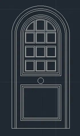
Dimleniar : Create and Place the Dimension lines as shown in figure
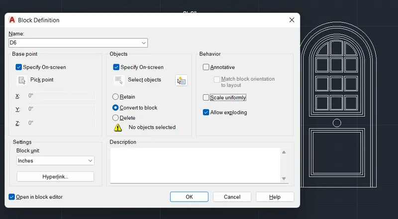
Block Edit : Select Block editor and Specify the name as "D5"
Base point as Specify on screen
Objects as Specify on screen
check the "Convert to Block"
Click ok
Select the basepoint and objects and Close the blockeditor
Result :
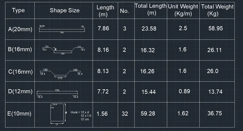
Aim: To create bare bending schedule for a given bar as a block and inserting them on the table as shown in the Figure, in AutoCAD.
Introduction: The bar details are created using primarily the Rectangle and Line tools. The procedure of drawing is explained in detail with diagrams of each step and the final result is given.
Procedure :
Go to START MENU, select AutoCAD 2022.
• In the Command line type in: STARTUP [ENTER]
• Enter new value of startup: 1
• Go to Application Menu and select New
• In the 'Create New Drawing' dialog box, we do the Advanced Setup and select the 'Decimal' unit of measurement and select precision as 0,0
• Set the limits by entering LIMITS in the Command tab. The lower-left corner is specified as 0,0 and the upper-right corner is specified as 10000,10000
• Enter 'UNITS' command in the command tab.
• In the Drawing Units dialog box, select 'Decimal' in Type; 0,0 in Precision; and 'Millimeters' in Insertion scale.
• Click on 'OK'.
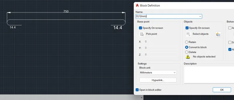
Line :specify the lenghth of the line as 750.
Arc: select the Start, End and Direction option and draw an arc on both ends of the line.
Dimleniar : Select the first point and second point of the object to be measured, then drag the dimension line to the desired location. Repeat for all the objects to be measured.
Mtext : Specify the start point of text as required. Font : Arial
Enter text height as 40.
Copy : select and Copy the text box to wherever necessary.
Edit Text : select and edit the text boxes as required in appropriate location.
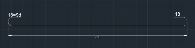
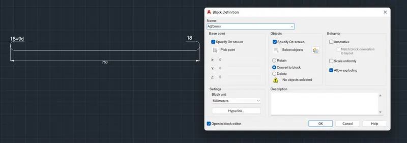
Block Edit : Select Block editor and Specify the name as "A(20mm)"
Base point as Specify on screen
Objects as Specify on screen
check the "Convert to Block"
Click ok
Select the basepoint and objects and Close the blockeditor
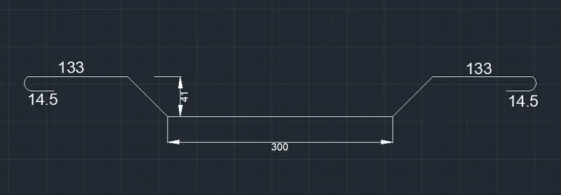
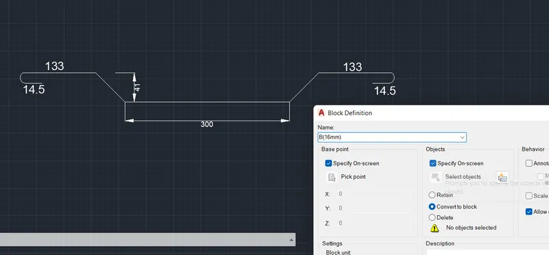
Line :specify the lenghth of the line as 300.
Arc: select the Start, End and Direction option and draw an arc on both ends of the line.
Line : Draw an Inclined line to show the inclination of the line and complete the object as shown in figure
Dimleniar : Select the first point and second point of the object to be measured, then drag the dimension line to the desired location. Repeat for all the objects to be measured.
Mtext : Specify the start point of text as required. Font : Arial
Enter text height as 40.
Copy : select and Copy the text box to wherever necessary.
Edit Text : select and edit the text boxes as required in appropriate location.
Block Edit : Select Block editor and Specify the name as "B(16mm)"
Base point as Specify on screen
Objects as Specify on screen
check the "Convert to Block"
Click ok
Select the basepoint and objects and Close the blockeditor
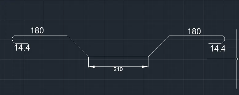
Line :specify the lenghth of the line as 210.
Arc: select the Start, End and Direction option and draw an arc on both ends of the line.
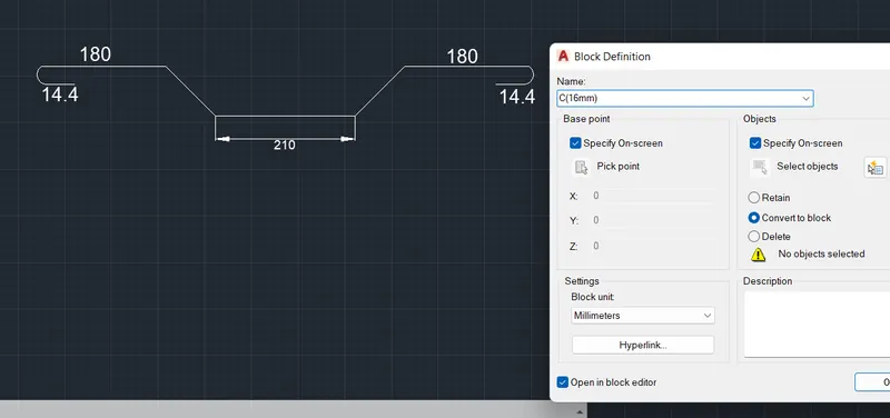
Line : Draw an Inclined line to show the inclination of the line and complete the object as shown in figure
Dimleniar : Select the first point and second point of the object to be measured, then drag the dimension line to the desired location. Repeat for all the objects to be measured.
Mtext : Specify the start point of text as required. Font : Arial
Enter text height as 40.
Copy : select and Copy the text box to wherever necessary.
Edit Text : select and edit the text boxes as required in appropriate location.
Block Edit : Select Block editor and Specify the name as "C(16mm)"
Base point as Specify on screen
Objects as Specify on screen
check the "Convert to Block"
Click ok
Select the basepoint and objects and Close the blockeditor
Line :specify the lenghth of the line as 750
Arc: select the Start, End and Direction option and draw an arc on both ends of the line.
Dimleniar : Select the first point and second point of the object to be measured, then drag the dimension line to the desired location. Repeat for all the objects to be measured.
Mtext : Specify the start point of text as required. Font : Arial
Enter text height as 40.
Copy : select and Copy the text box to wherever necessary.
Edit Text : select and edit the text boxes as required in appropriate location.
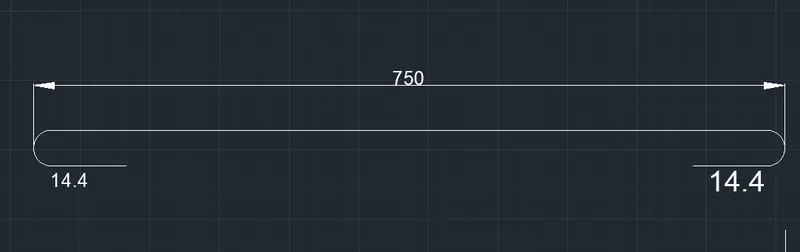
Block Edit : Select Block editor and Specify the name as "D(12mm)"
Base point as Specify on screen
Objects as Specify on screen
check the "Convert to Block"
Click ok
Select the basepoint and objects and Close the blockedit
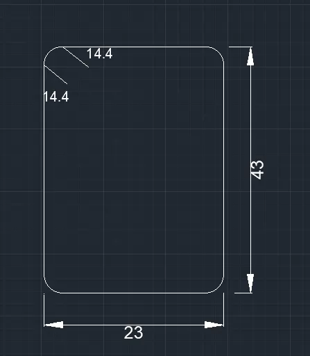
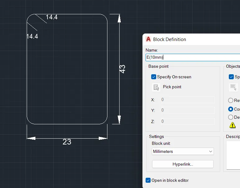
Rectangle: specify the size as 23,43
Explode: select and Explode the Rectangle
Fillet : Specify the Radious pf ther rectangle as 25mm and Choose all the Corners
Line : Draw the hook lines as 14.4mm
Dimleniar : Select the first point and second point of the object to be measured, then drag the dimension line to the desired location. Repeat for all the objects to be measured.
Mtext : Specify the start point of text as required. Font : Arial
Enter text height as 40.
Copy : select and Copy the text box to wherever necessary.
Edit Text : select and edit the text boxes as required in appropriate location.
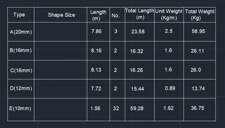
Rectangle : Specify the size of the rectangle as 5500,3000
Explode: Select and explode the Rectangle
Offset : Top to bottom -specify an offset distance of 400,500 repeat 500 in 4 times
Left to right -700,1400,600,400,600 and offset 600 twice again
Trim : Cutoff the unwanted lines
Mtext : Specify the start point of text as required. Font : Arial
Enter text height as 100.
Copy : select and Copy the text box to wherever necessary.
Edit Text : select and edit the text boxes as required in appropriate location.
Insert : Select and Insert the appropriate block infront of its description
Result: