Creating Bar Bending schedule, Different Door types, and Creation of standard drawing templates using AutoCad
1.AIM
To create the templates , inserting text
COMMANDS USED:
- Line
- Block
- Insert
- Attributes
- Text
- dimension
- offset trim
PROCEDURE
STEP1
- Open a new file
- In the command line type units , select the units and also set the precision
- In the command line type 'LIMITS' and specify the limits at lower left corner and upper right corner as
- Then zoom all
STEP2
CUSTOM1_titleblock
- Using the line command draw the table
- using mtext enter the text
- Using property tab change the colour
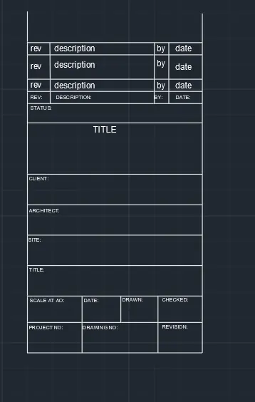
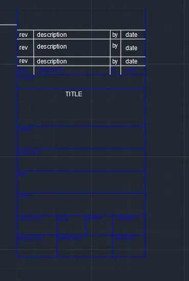
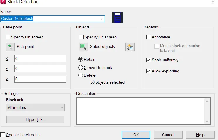
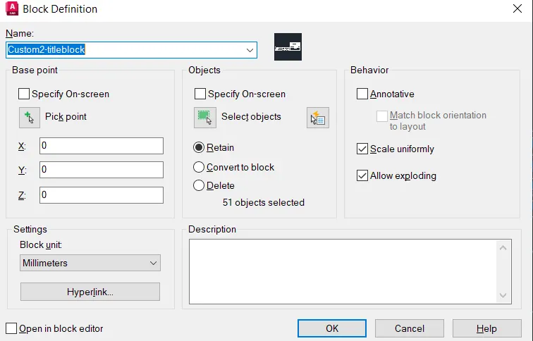
- Creating block using block command
- Name the block as "CUSTOM1_titleblock" then pick the point and select the object then ok
STEP3
CUSTOM 2_titleblock
- Using the line command draw the table
- using mtext enter the text
- Using property tab change the colour
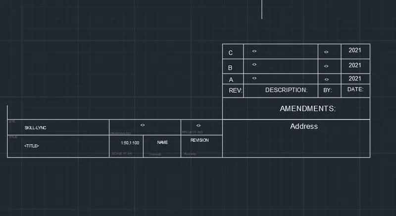
- Creating block using block command
- Name the block as "CUSTOM2_titleblock" then pick the point and select the object then ok
RESULT
Custom1-tiltleblock and Custom2-titleblock created
---------------------------------------------------------------------------------------------------------------------------------------------
2.AIM
To create the doors type for warehouse and placing it in blocks
COMMANDS USED:
- Line
- Block
- Insert
- Text
- trim
- offset
- rectangle
PROCEDURE
DOOR 1
STEP1
- Open a new file
- In the command line type units , select the units and also set the precision
- In the command line type 'LIMITS' and specify the limits at lower left corner and upper right corner as
- Then zoom all
STEP2
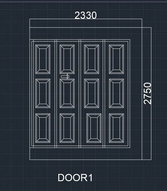
- Using line command draw a line of 2330mm then perpendicular to that draw a line of 2750mm and then towards left draw a line of 2330mm then down 2750mm
- Then press escape
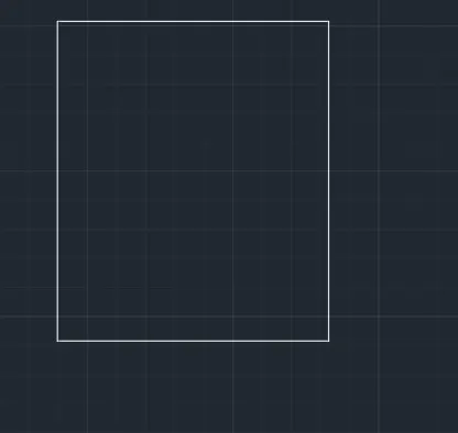
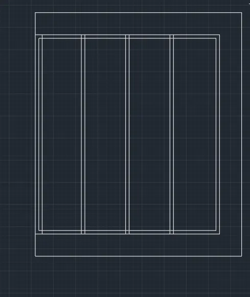
- Using offset command offset 250mm from top, bottom and right side of the above drawn rectangle
- Trim the unwanted lines
- Then again offset the offseted rectangle by 40mm and divide the offseted line into 4 segments
- Using "DDPTYPE" command select the style of point and make it visible
- From the division point draw lines vertically to divide it into shutters
STEP3
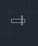
- Lock is created using rectangle and filleted the corners of the rectangle with radius 10mm
- Panels are created using rectangle with size 300*600mm
- Using offset command offset the rectangle by 20mm and offset it again from the second rectangle by 60mm
- Using line command join the corners of the outside and inside of the rectangle.
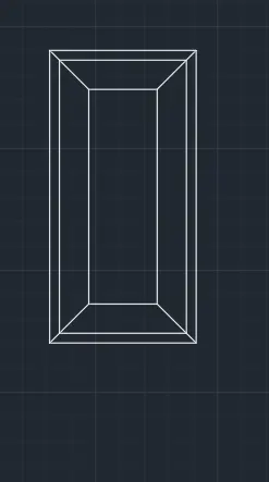
- Using copy command panels are placed where ever required
- Using dimlinear command dimensions are marked
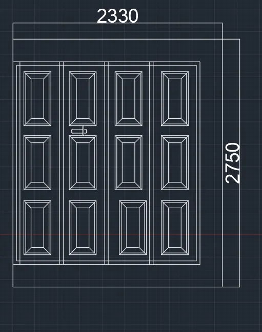
STEP4
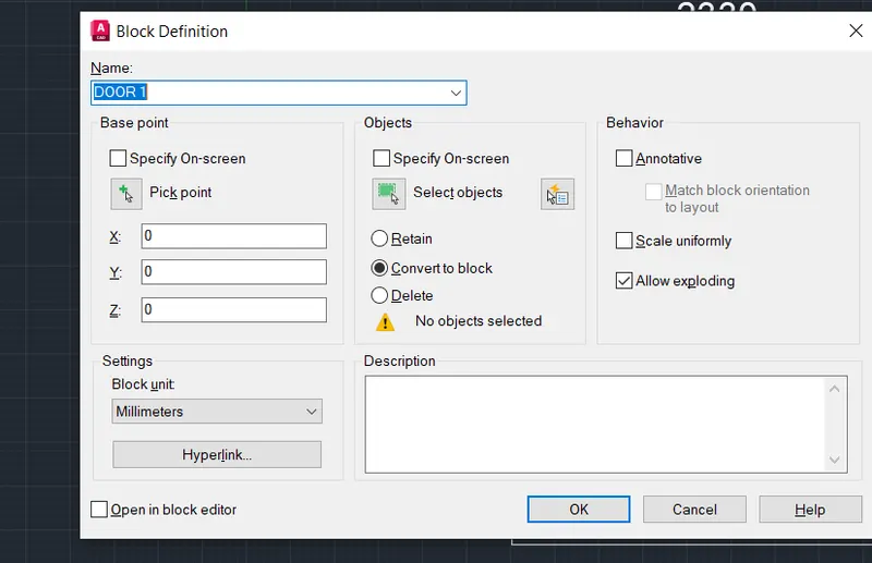
- Creating block using block command
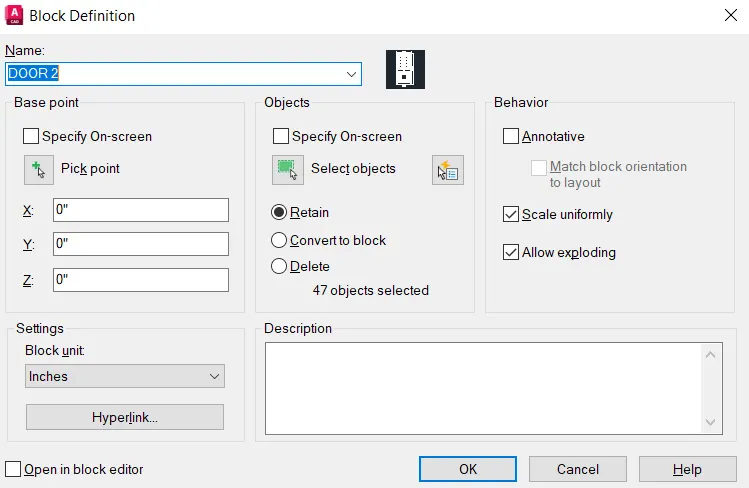
- Name the block as DOOR 1 then pick the point and select the object then ok
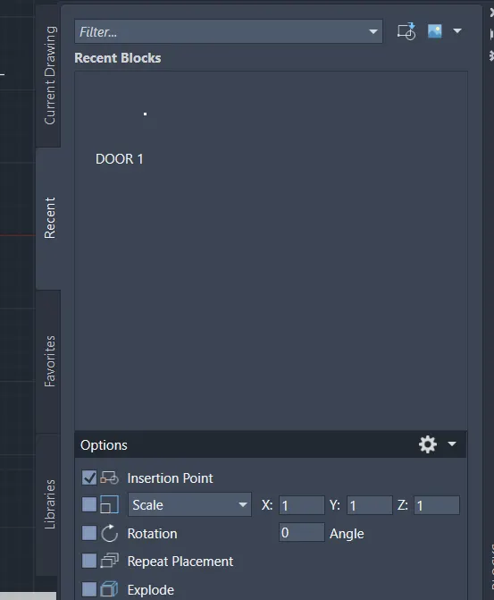
- Insert the created block using insert command
DOOR 2
STEP1
- Open a new file
- In the command line type units , select the units and also set the precision
- In the command line type 'LIMITS' and specify the limits at lower left corner and upper right corner as
- Then zoom all
STEP2
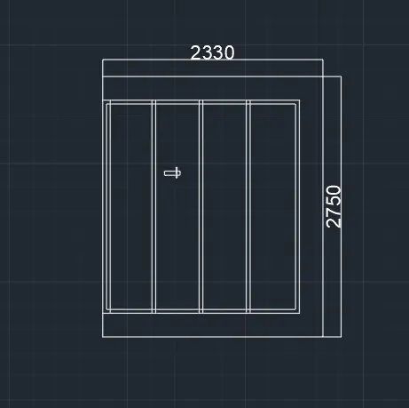
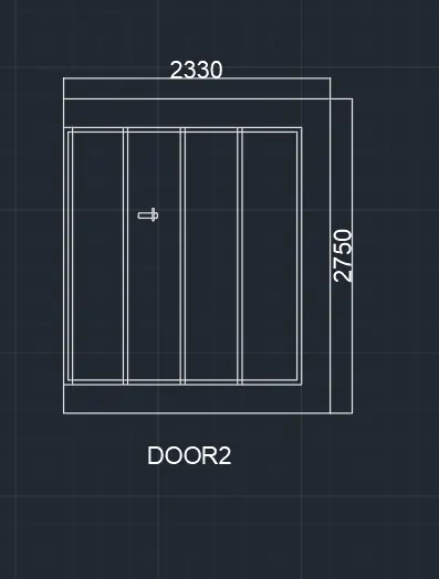
- Using line command draw a line of 2330mm then perpendicular to that draw a line of 2750mm and then towards left draw a line of 2330mm then down 2750mm
- Then press escape
- Using offset command offset 250mm from top, bottom and right side of the above drawn rectangle
- Trim the unwanted lines
- Then again offset the offseted rectangle by 40mm and divide the offseted line into 4 segments
- Using "DDPTYPE" command select the style of point and make it visible
- From the division point draw lines vertically to divide it into shutters
STEP3
- Lock is created using rectangle and filleted the corners of the rectangle with radius 10mm
- Using dimlinear command dimensions are marked
STEP4
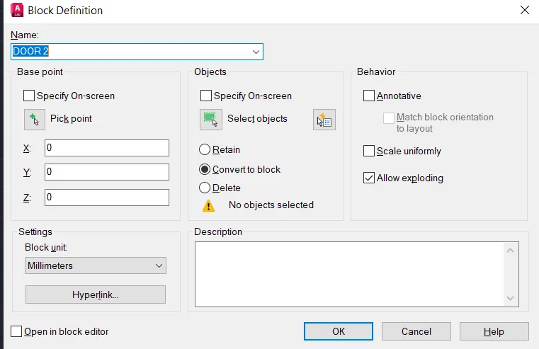
- Creating block using block command
- Name the block as DOOR 2 then pick the point and select the object then ok
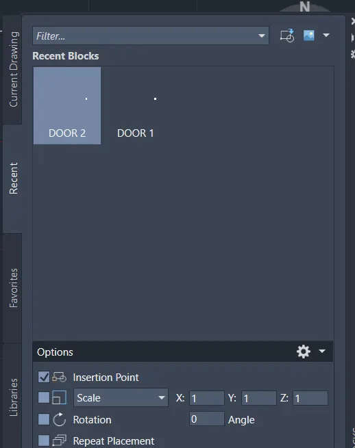
- Insert the created block using insert command
RESULT
DOOR1 AND DOOR 2 are created using autocad
---------------------------------------------------------------------------------------------------------------------------------------------
3.AIM
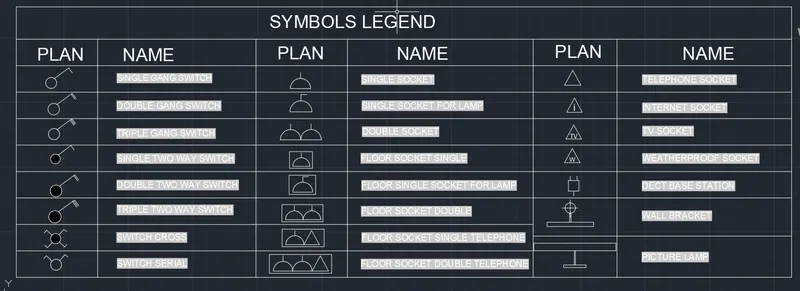
To create each electrical symbol as a block with the name given in the legend. After creating the blocks arrange them in the legend
COMMANDS USED:
- Line
- Block
- Insert
- Field
- Text
- dimension
- offset
- trim
- rectangle
- circle
- hatch
PROCEDURE
STEP1
- Open a new file
- In the command line type units , select the units and also set the precision
- In the command line type 'LIMITS' and specify the limits at lower left corner and upper right corner as
- Then zoom all
STEP2
CREATING ELETRICAL SYMBOLS
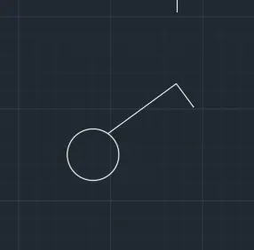
1.Single gang switch
- Using circle command draw a circle of radius 70mm
- Then by using line command draw an inclined line vertical and horizontal line perpendicular to the inclined line
2. Double gang switch
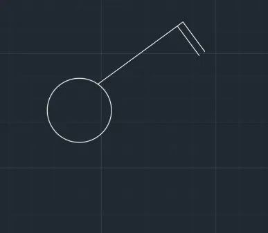
- Using circle command draw a circle of radius 70mm
- Then by using line command draw an inclined line vertical and 2 horizontal line perpendicular to the inclined line
3.Triple gang switch
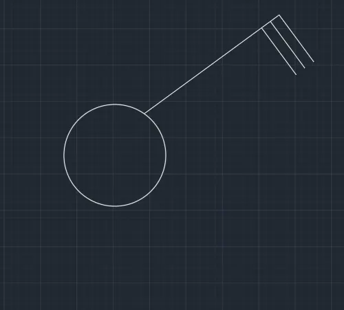
- Using circle command draw a circle of radius 70mm
- Then by using line command draw an inclined line vertical and 3 horizontal line perpendicular to the inclined line
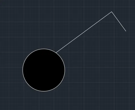
4.Single two-way switch
- Same procedure as single gang switch
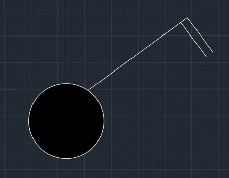
5.Double two-way switch
- Same procedure as double gang switch
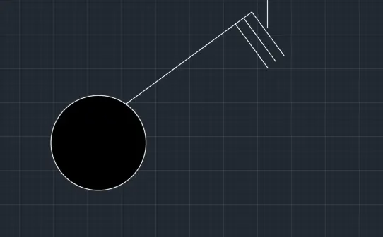
6.Triple two-way switch
- Same procedure as triple gang switch
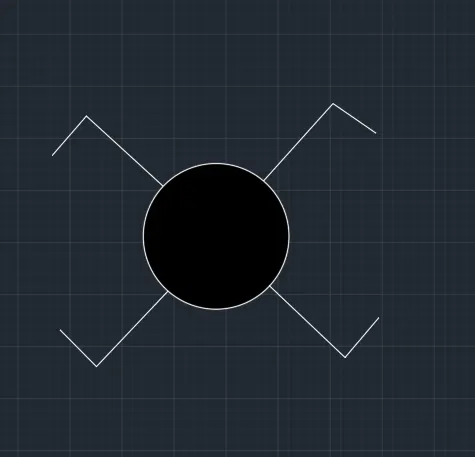
7.Switch cross
- Using circle command draw a circle of radius 70mm
- Then by using line command draw an inclined vertical and perpendicular horizontal
- Mirror the line in both directions
8.Switch serial
- Using the copy command copy the switch cross and delete the bottom lines
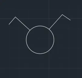
9.Single socket
- Using circle command draw a circle
- Divide the circle into half
- Using the line command draw a line at the top
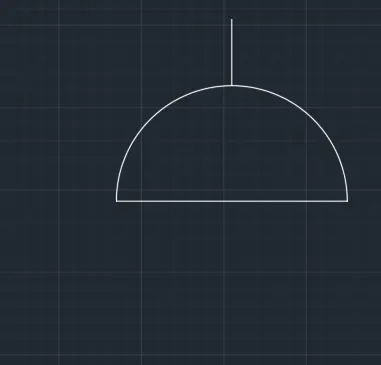
10.Single socket for lamp
- Using copy command copy the single socket
- Using line command draw a horizontal line perpendicular to vertical
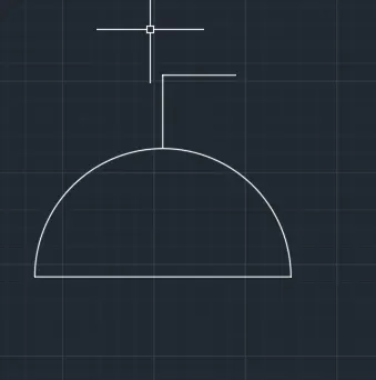
11.Double socket
- Draw a single socket
- Using copy command copy the single socket
- Place it by keeping the snap on
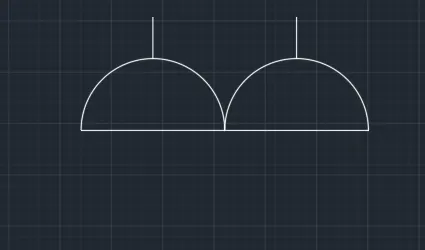
12.Floor socket single
- Using rectangle command draw a rectangle surrownding single socket
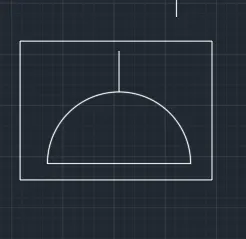
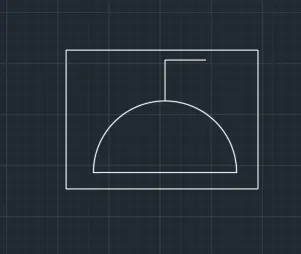
13.Floor single socket for lamp
- Using rectangle command draw a rectangle surrownding single socket for lamp
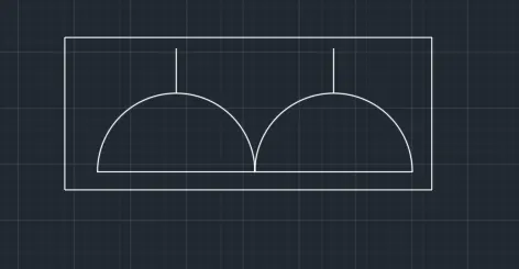
14.Floor socket double
- Using rectangle command draw a rectangle surrownding double socket
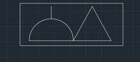
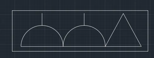
15.Floor socket single telephone
- Draw a single socket , then a traingle
- surrownding that a rectangle is drawn
15.Floor socket double telephone
- Draw 2 single socket , then a traingle
- surrownding that a rectangle is drawn
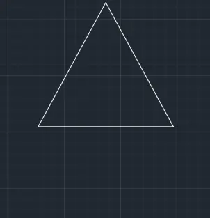
16.Telephone socket
- Draw a triangle
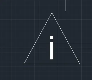
17.Internet socket
- Draw a triangle and insert text "i" in the triangle
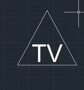
18.TV socket
- Draw a triangle and insert text "TV" in the triangle
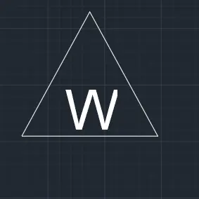
19.Weatherproof socket
- Draw a triangle and insert text "W" in the triangle
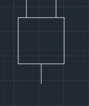
20.Duct base section
- Draw a rectangle
- Then using line command draw lines as required
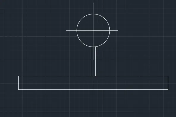
21.Wall bracket
- Using circle command draw a circle and draw cross lines inside the circle
- using rectangular command draw rectangle as base
- Using line command draw line connecting the rectangle and circle
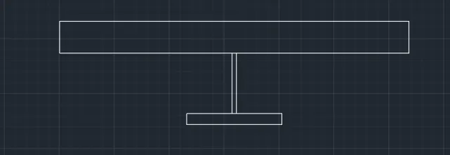
22.Picture lamp
- Using rectangular command draw two rectangle
- By using line command connect the two rectangles
STEP3
CREATING BLOCKS
- Using block command "B" give name as single gang switch
- Pick a point
- Select the object
- Tick scale uniformly and allow exploding options
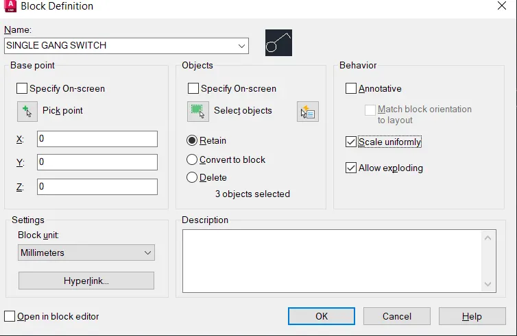
- Same way make each electrical symbol as block with their respective names
STEP4
CRAETING TABLE AND ARRANGING THEM
- Create a table of 10 rows and 6 columns
- Place the block in respective positions
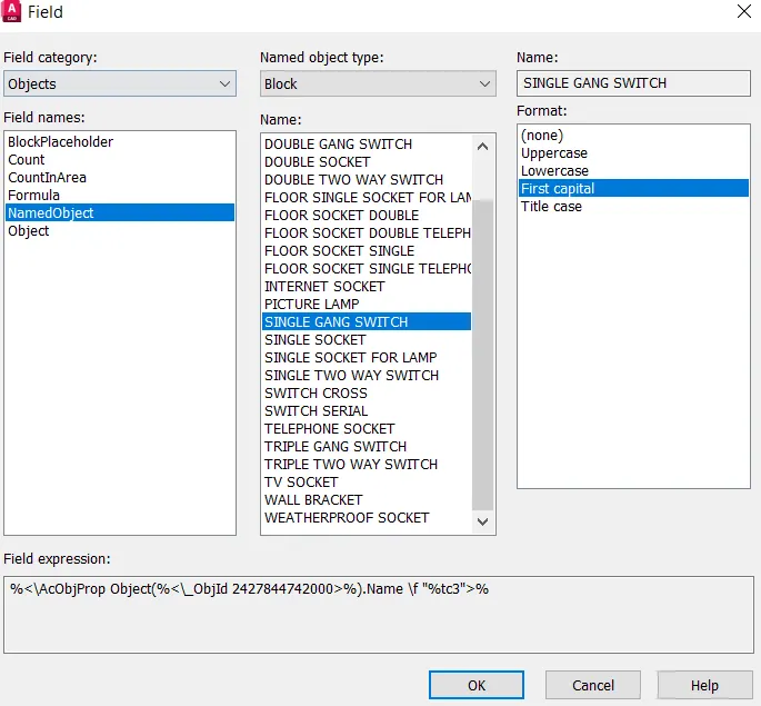
- To enter the text with the block
- Go to insert - select field-select object- select block
RESULT
---------------------------------------------------------------------------------------------------------------------------------------------
4.AIM
To create the doors for residential building as blocks.
COMMANDS USED:
- Line
- Block
- Insert
- Text
- dimension
- rectangle
- circle
- offset
- trim
PROCEDURE
STEP1
- Open a new file
- In the command line type units , select the units and also set the precision
- In the command line type 'LIMITS' and specify the limits at lower left corner and upper right corner as
- Then zoom all
STEP2
DOOR 1
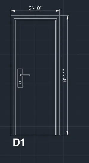
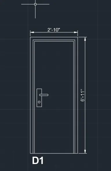
- Using rectangle command draw a rectangle with dimensions 2'-10" and 6'-11"
- Using offset command offset the rectangle by 2" and then again the offsetted rectangle by 1"
- Using trim command trim the unwanted lines
- For door lock draw two rectangle perpendicular to each other
- Using dimlinear command dimensions are marked
- Using multitext text is written
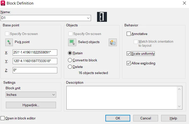
- Using block command "B" create block of Door 1
- give name as D1
- Pick the corner point
- Select the object
- then block is created
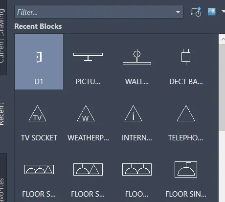
- Then inserting the block
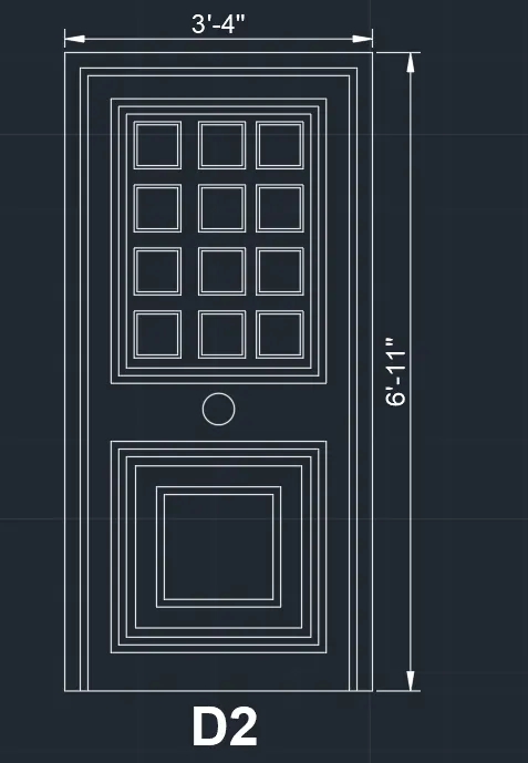
DOOR 2
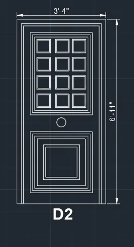
- Using rectangle command draw a rectangle with dimensions 3'-4" and 6'-11"
- Using offset command offset the rectangle by 2" and then again the offsetted rectangle by 1"
- Using trim command trim the unwanted lines
- Then using rectangular , offset and array command door is completely drawn
- Using dimlinear command dimensions are marked
- Using multitext text is written
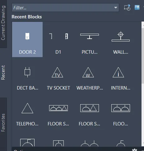
- Using block command "B" create block of Door 2
- give name as D2
- Pick the corner point
- Select the object
- then block is created
- Then inserting the block
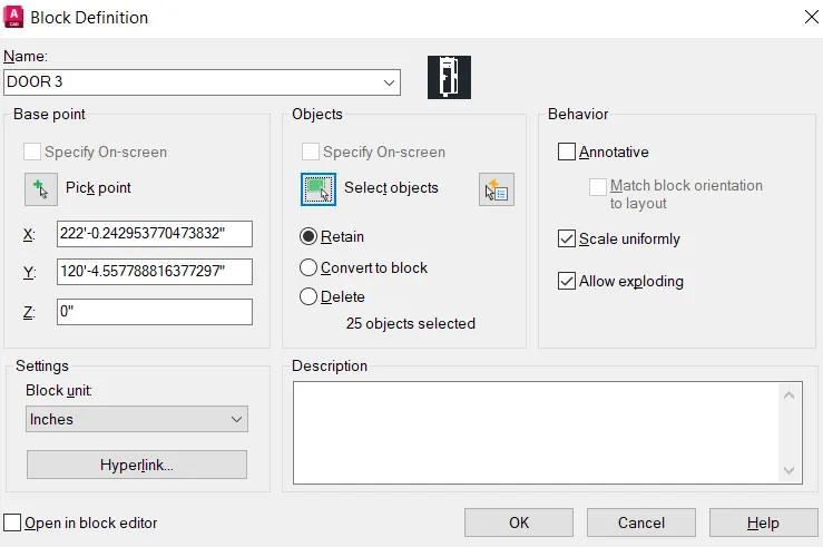
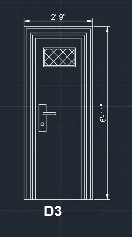
DOOR 3
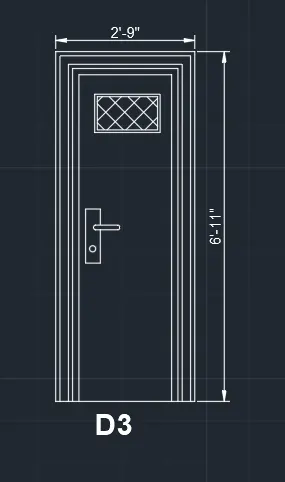
- Using rectangle command draw a rectangle with dimensions 3'-4" and 6'-11"
- Using offset command offset the rectangle by 1" and then again the offsetted rectangle by 2", offset by 1' and 1.5"
- Draw a rectangle for ventilation and hatch it inside using hatch command
- Using trim command trim the unwanted lines
- For door lock draw two rectangle perpendicular to each other
- Using dimlinear command dimensions are marked
- Using multitext text is written
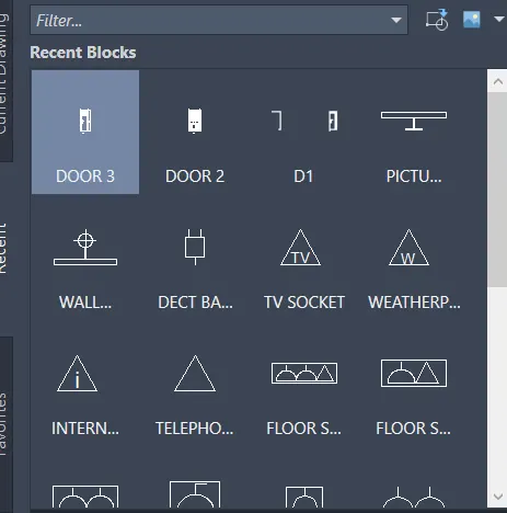
- Using block command "B" create block of Door 3
- give name as D3
- Pick the corner point
- Select the object
- then block is created
- Then inserting the block
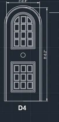
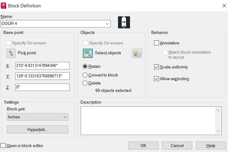
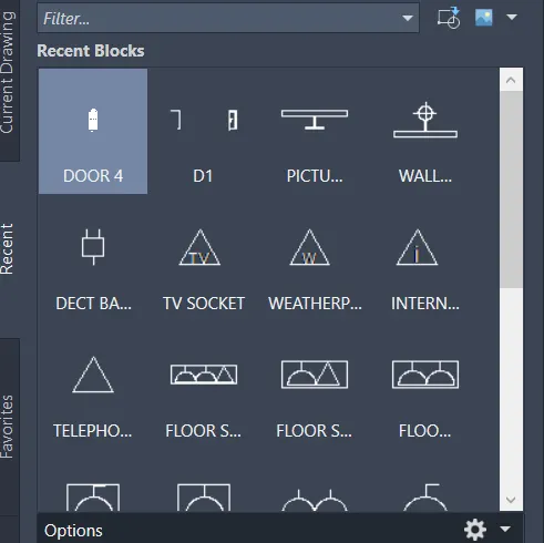
DOOR 4
- Using rectangle command draw a rectangle
- Explode it and create an arc with start , center and end
- using rectangle command , offset and array complete the draw
- Using block command "B" create block of Door 4
- give name as D4
- Pick the corner point
- Select the object
- then block is created
- Then inserting the block
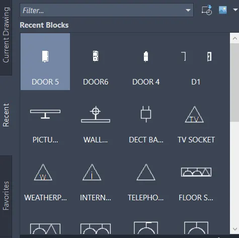
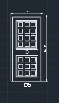
DOOR 5
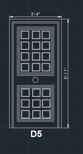
- Using rectangle command draw a rectangle with dimensions 3'-4" and 6'-11"
- Using offset command offset the rectangle by 2" and then again the offsetted rectangle by 1"
- Using trim command trim the unwanted lines
- Then using rectangular , offset and array command door is completely drawn
- Using dimlinear command dimensions are marked
- Using multitext text is written
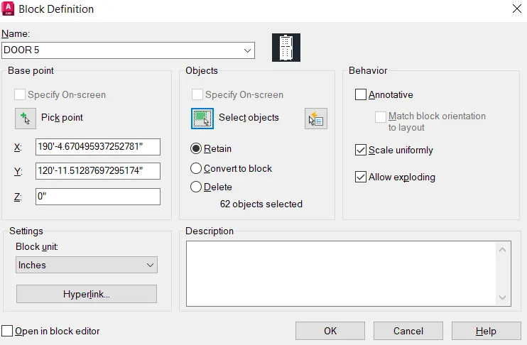
- Using block command "B" create block of Door 5
- give name as D5
- Pick the corner point
- Select the object
- then block is created
- Then inserting the block
DOOR 6
- Same as d4
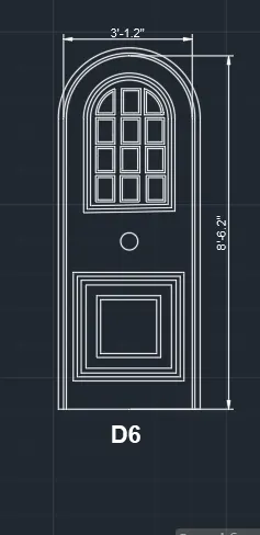
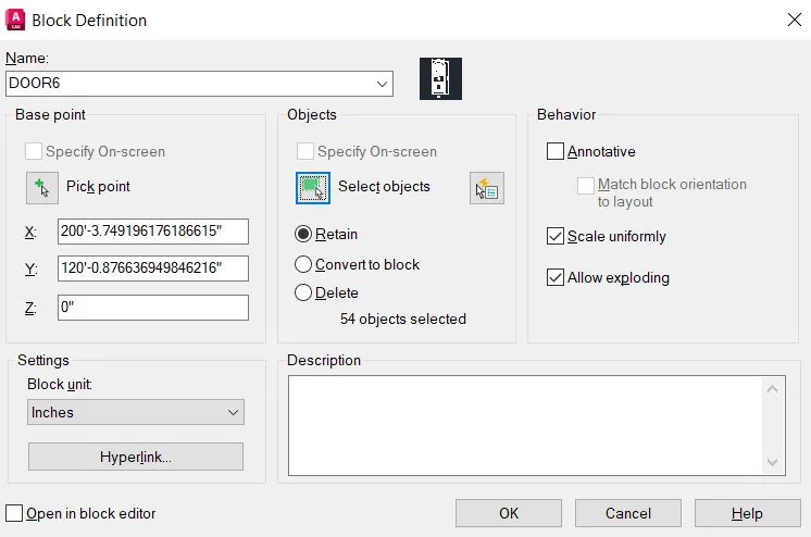
- Using block command "B" create block of Door 6
- give name as D6
- Pick the corner point
- Select the object
- then block is created
- Then inserting the block
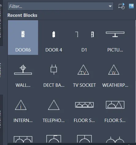
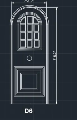
RESULT
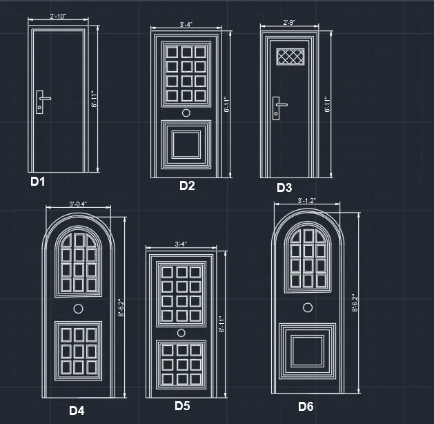
5.AIM
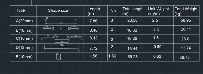
To create create bar bending schedule and create it as block.
COMMANDS USED:
- Line
- Block
- Insert
- Text
- dimension
- rectangle
- circle
- offset
- trim
PROCEDURE
STEP1
- Open a new file
- In the command line type units , select the units and also set the precision
- In the command line type 'LIMITS' and specify the limits at lower left corner and upper right corner as
- Then zoom all
STEP2
DRAWING SHAPES
1.A -20mm
- Using line command draw a line of 750mm
- create bend using arc and mirror it to the other side using mirror command
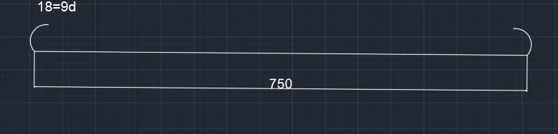
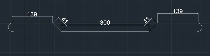
2.B-16mm
- Using line command draw a line of 300mm
- draw a vertical line of 41 and again draw a horizontal line of 139
3.C-16mm
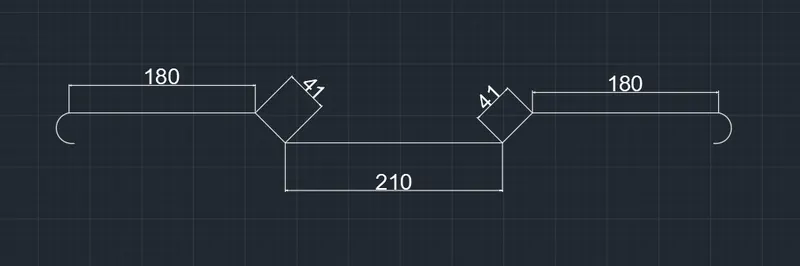
- Using line command draw a line of 210 mm
- draw a vertical line of 41 and again draw a horizontal line of 180
4.D-12mm
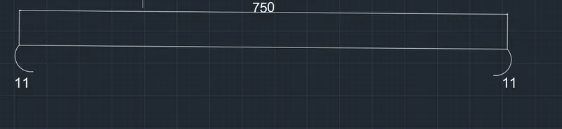
- Using line command draw a line of 750mm
- create bend using arc and mirror it to the other side using mirror command
4.E-10mm
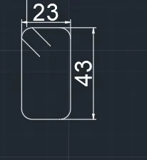
- using rectangle command draw a rectangle of 23 and 43 and fillet the corner by 5
STEP3
-
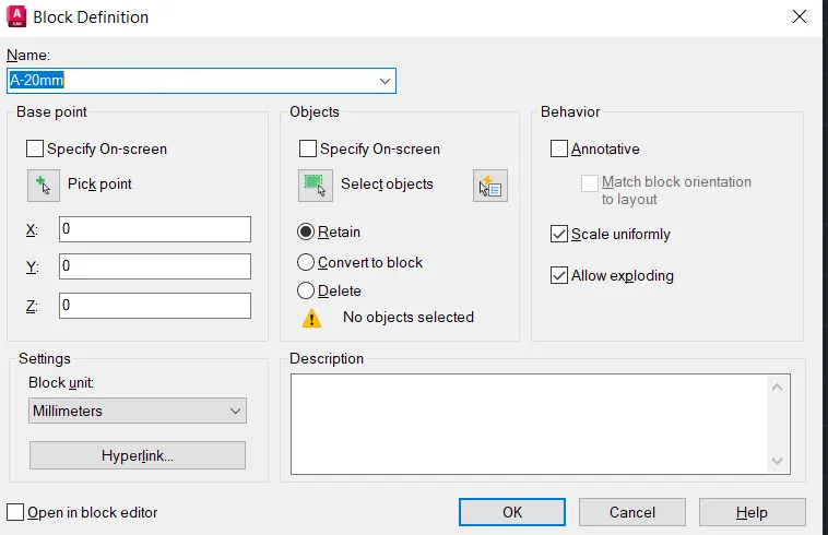
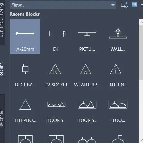
CREATING BLOCKS
- Using block command "B" give name as single gang switch
- Pick a point
- Select the object
- Tick scale uniformly and allow exploding options
STEP4
CRAETING TABLE AND ARRANGING THEM
- Create a table of 6 rows and 7columns
- Place the block in respective positions
- Using multiline text enter the text in the table
RESULT
------------------------------------------------------------------------------------------------------------------------------------------