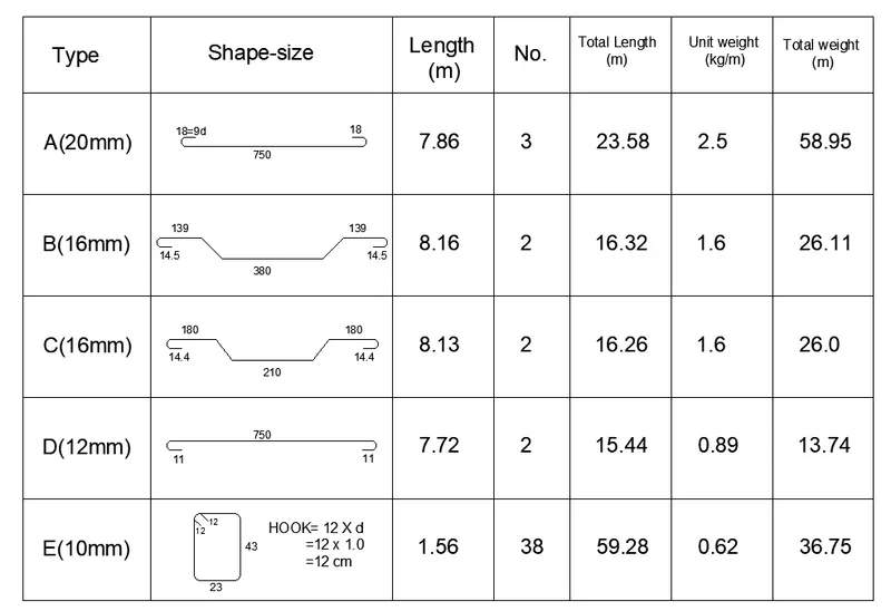
Creating Bar Bending schedule, Different Door types, and Creation of standard drawing templates using AutoCad
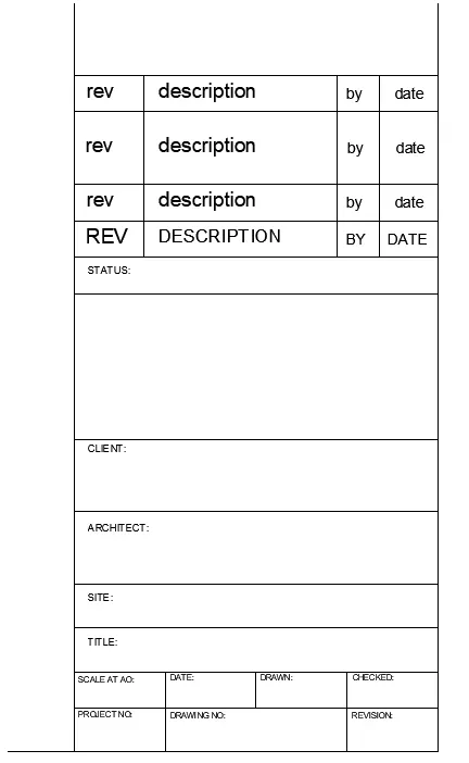
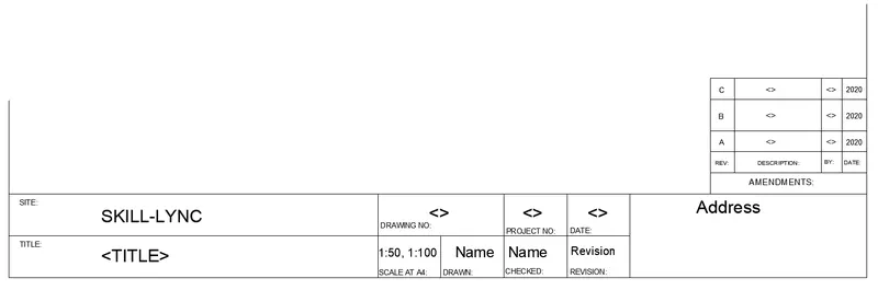
1) AIM: To create the templates as shown in Figures and save it as a block with provided names.
PROCEDURE:
- Open cad application in the pc and set all the limits required.
- Set the units as required for drawing. Set units in Decimal and scale in Millimeters.
- Keep ortho on for easily drawing lines in right angles.
- Draw the table using the Line command. After drawing the table using lines then trim off the extra lines.
- Using the offset command we can make boxes to insert texts.
- Using texts type the given texts and do the naming.
- After completing the drawing next we have to make a block of these drawings.
- Type Block in command and a dialogue box will appear.
- First name the drawing as mentioned.
- Select a point where the drawing will be pinned or when ever for next time we use that drawing it appears using that point as base.
- Select the object that has to be done as block.
- Now we have to set the behavior of the object.
- There are three types of behavior Annotive, Scale uniformly and allow exploding.
- Select as required and press ok on the dialogue box.
- There will also be a small display where the preview of selected drawing will be shown.
- Set the Block unit in required one, here i have made millimeters because the drawing is in the same unit so.
RESULT:
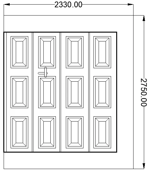
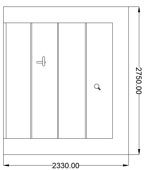
2) AIM: To create the doors type for warehouse as shown and create the blocks of this door type after creating them.
PROCEDURE:
- Open cad application in the pc and set all the limits required.
- Set the units as required for drawing. Set units in Decimal and scale in Millimeters.
- Keep ortho on for easily drawing lines in right angles.
- Select Line and draw the outer lines of the door as per given dimensions.
- Then using offset give the thickness of panels.
- Then draw the rectangle in the latest lines and using offset make all the required thickness.
- Break the rectangle using Xplode and divide the line in required segments.
- Draw the lines from all the divided lines and show the small glazed parts of door.
- Once the front view is completed then Start with the inside view of the door.
- Make a handle and a lick using rectangle and circle command.
- After completing the drawing next we have to make a block of these drawings.
- Type Block in command and a dialogue box will appear.
- First name the drawing as mentioned.
- Select a point where the drawing will be pinned or when ever for next time we use that drawing it appears using that point as base.
- Select the object that has to be done as block.
- Now we have to set the behavior of the object.
- There are three types of behavior Annotive, Scale uniformly and allow exploding.
- Select as required and press ok on the dialogue box.
- There will also be a small display where the preview of selected drawing will be shown.
- Set the Block unit as required, here i have made it in millimeters because the drawing provided is in millimeters.
RESULT:
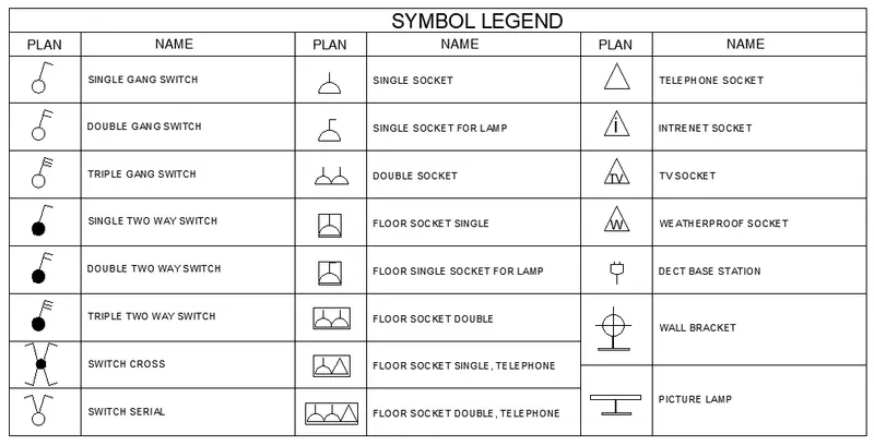
3) AIM: To create each symbol as a block with the name given in the legend. After creating the blocks arrange them in the legend.
PROCEDURE:
- Open cad application in the pc and set all the limits required.
- Set the units as required for drawing. Set units in Decimal and scale in Millimeters.
- Keep ortho on for easily drawing lines in right angles.
- Draw the table using the Line command. After drawing the table using lines then trim off the extra lines.
- Using the offset command we can make boxes to insert texts.
- Draw the plan of each material or switches in the mentioned way.
- After completing the drawing next we have to make a block of these drawings.
- Type Block in command and a dialogue box will appear.
- First name the drawing as mentioned.
- Select a point where the drawing will be pinned or when ever for next time we use that drawing it appears using that point as base.
- Select the object that has to be done as block.
- Now we have to set the behavior of the object.
- There are three types of behavior Annotive, Scale uniformly and allow exploding.
- Select as required and press ok on the dialogue box.
- There will also be a small display where the preview of selected drawing will be shown.
- Set the Block unit in required one, here i have made millimeters because the drawing is in the same unit so.
- Now do the attribute for the text.
- In the Attribute Definition dialog box, set the attribute modes and enter tag information, location, and text options.
- Press okay and then the text is displayed.
- Place where the text is required and then make it a clock for the required plan or drawing.
RESULT:
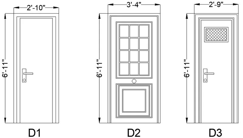
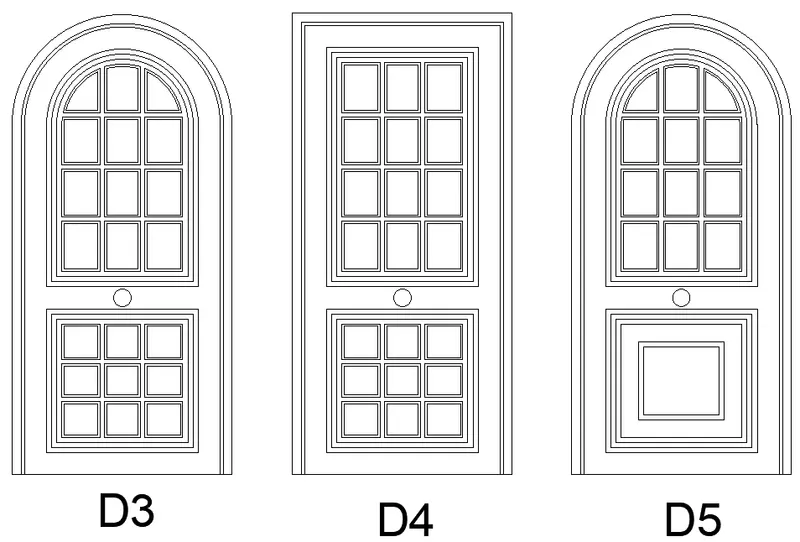
4) AIM: To create the door type for residential building as a block.
PROCEDURE:
- Open cad application in the pc and set all the limits required.
- Set the units as required for drawing. Set units in Decimal and scale in Inches.
- Keep ortho on for easily drawing lines in right angles.
- Select Line and draw the outer lines of the door as per given dimensions.
- Then using offset give the thickness of panels.
- Then draw the rectangle in the latest lines and using offset make all the required thickness.
- Break the rectangle using Xplode and divide the line in required segments.
- Draw the lines from all the divided lines and show the small glazed parts of door.
- Do the same for the other drawing but the difference is where there is arc use arc command and draw it.
- Use offset command to complete the table and trim off the extra lines.
- Make a handle and a lick using rectangle and circle command.
- After completing the drawing next we have to make a block of these drawings.
- Type Block in command and a dialogue box will appear.
- First name the drawing as mentioned.
- Select a point where the drawing will be pinned or when ever for next time we use that drawing it appears using that point as base.
- Select the object that has to be done as block.
- Now we have to set the behavior of the object.
- There are three types of behavior Annotive, Scale uniformly and allow exploding.
- Select as required and press ok on the dialogue box.
- There will also be a small display where the preview of selected drawing will be shown.
- Set the Block unit as required, here i have made it in millimeters because the drawing provided is in Inches.
- Do the dimensions as per required, make the size of text and arrow as that are visible clearly.
RESULT:
5) AIM: To create each shape as a block as shown in the Figure. Save the block and insert them on the table.
PROCEDURE:
- Open cad application in the pc and set all the limits required.
- Set the units as required for drawing. Set units in Decimal and scale in Centimeter.
- Keep ortho on for easily drawing lines in right angles.
- Select Line and draw the outer lines of the table with required dimensions.
- Using the offset command complete the table.
- After completing the tables trim off the extra lines.
- Now do the naming of the table using text command.
- After that do the shape drawings using the given dimensions.
- Using polyline command we can also do the shapes of the bars.
- Using text command we have to do the naming and mention the dimension details.
- Now do the attribute for the text.
- In the Attribute Definition dialog box, set the attribute modes and enter tag information, location, and text options.
- Press okay and then the text is displayed.
- After completing the drawing next we have to make a block of these drawings.
- Type Block in command and a dialogue box will appear.
- First name the drawing as mentioned.
- Select a point where the drawing will be pinned or when ever for next time we use that drawing it appears using that point as base.
- Select the object that has to be done as block.
- Now we have to set the behavior of the object.
- There are three types of behavior Annotive, Scale uniformly and allow exploding.
- Select as required and press ok on the dialogue box.
- There will also be a small display where the preview of selected drawing will be shown.
- Set the Block unit as required, here i have made it in millimeters because the drawing provided is in Centimeter.
RESULT: