Creating Bar Bending schedule, Different Door types, and Creation of standard drawing templates using AutoCad
1Q]
A]
AIM: -
Create the Templates.
Use the Text and Attributes wherever required.
Save the Templates as Blocks.
PROCEDURE: -
Select Line command
Draw Table of 4 Rows and 4 Columns.
Select ANNONTATE in Ribbon
Under TEXT dialogue box
Choose Multiline Text tool
Using MTEXT label the details
Select command: ‘_STYLE
Create new style with Font name - Arial and Font Style – Regular
Set current.
Type Text in one of the rows.
1)REV,
2)DESCRIPTION,
3)BY,
4)DATE
Create ATTRIBUTES for the mentioned TEXTS
Select INSERT > BLOCK DEFINITION > DEFINE ATTRIBBUTES
Attribute Table pops up on the screen.
In MODE tick the LOCK POSITION, PRESET options.
INSERTION POINT: Specify on the screen
ATTRIBUTE:
Tag: REV
Prompt: What is the revision?
Default: rev
TEXT SETTINGS:
Justification: Left
Text Style:
Text Height:
After entering all the required data press OK.
Place the Attribute that we created under the REV column.
After finishing creating ATTRIBUTE for REV
Repeat the same process to create ATTRIBUTE for the rest of the TEXTS.
Place all the created attributes under their respective column.
Copy all the ATTRIBUTES created and paste in the respective Rows.
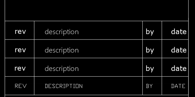
Create rows for rest of the text as given in the figure.
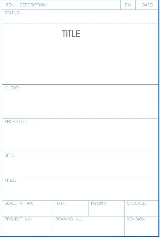
Create ATTRIBUTE for each of the Text available in all the Rows and Columns in the given figure.
Tag: Enter the Text to be visible
Prompt: write the question related to Tag
Default: Keep it Blank for this
TEXT SETTINGS:
Justification: Left
Text Style: standard
Text Height: as per the requirement
After entering all the required data press OK.
Place the ATTRIBUTES in their respective Rows.
Type B
Give NAME to the Block.
Pick a Point on the Object created as an Insertion Point.
Select objects and choose required object options and behaviour options.
press ok.
After converting to Block
The TEXT what we typed in the ATTRIBUTE Default box DISPLAYS IN THE BLOCK.
In this particular case we left the Default box blank.
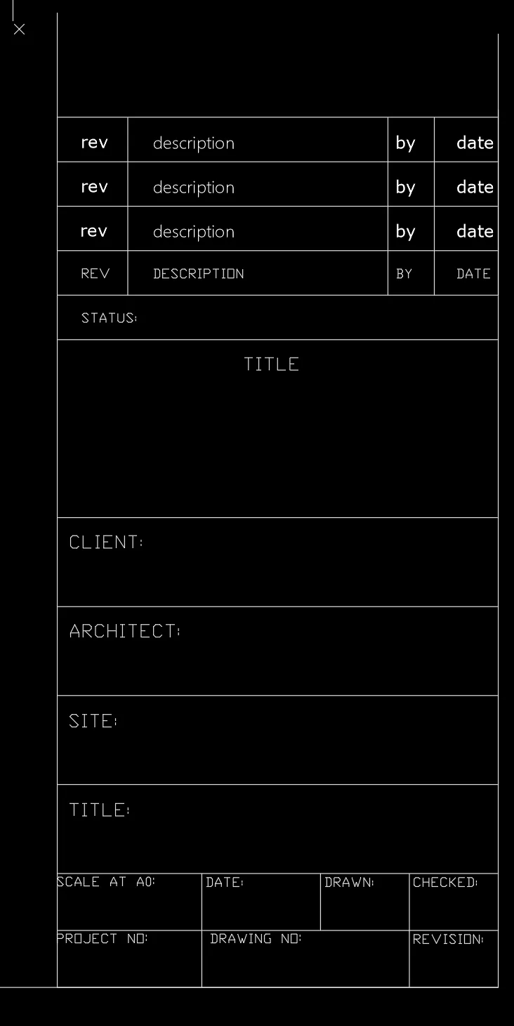
RESULT: -
We used TEXT, ATTRIBUTES and BLOCKS to create the Template
B]
AIM: -
Create the Templates.
Use the Text and Attributes wherever required.
Save the Templates as Blocks.
PROCEDURE: -
Select Line command
Draw Table as per requirement given in the figure.
Select ANNONTATE in Ribbon
Under TEXT dialogue box
Choose Multiline Text tool
Using MTEXT label the details
Select command: ‘_STYLE
Create new style with Font name - Arial and Font Style – Regular
Set current.
Type Text in one of the rows.
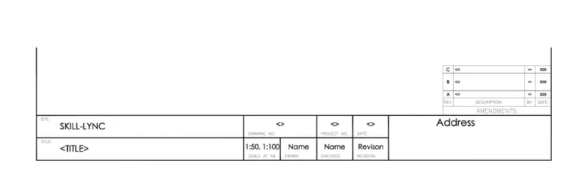
Create Tables and type the Text as given in figure.
After typing the TEXT in the respective boxes.
Create ATTRIBUTES for the mentioned TEXTS
Select INSERT > BLOCK DEFINITION > DEFINE ATTRIBBUTES
Attribute Table pops up on the screen.
In MODE tick the LOCK POSITION, PRESET options.
INSERTION POINT: Specify on the screen
ATTRIBUTE:
Tag: Enter the Text to be visible
Prompt: write the question related to Tag
Default: Required Value to be visible under Tag for the prompt Question
TEXT SETTINGS:
Justification: Left
Text Style: standard
Text Height: as per the requirement
After entering all the required data press OK.
Place the ATTRIBUTES in their respective Rows.
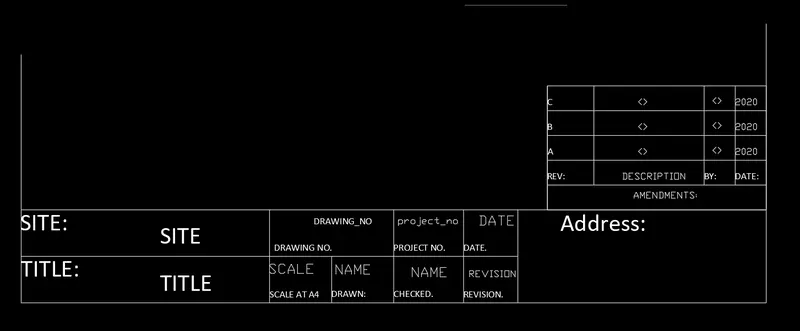
Type B
Give NAME to the Block.
Pick a Point on the Object created as an Insertion Point.
Select objects and choose required object options and behaviour options.
press ok.
After converting to Block
The TEXT what we typed in the ATTRIBUTE Default box DISPLAYS IN THE BLOCK
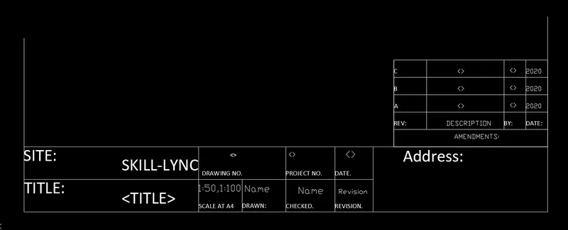
.
RESULT: -
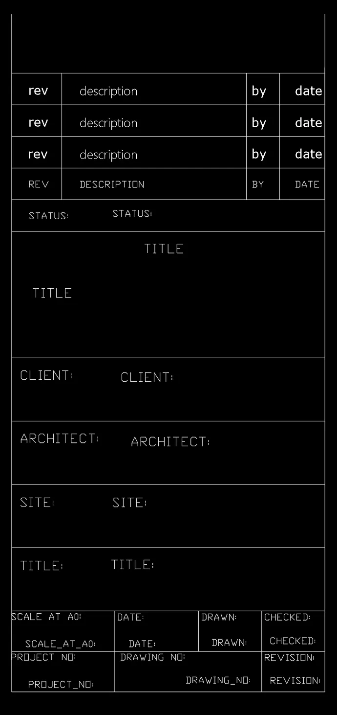
After converting to BLOCK the Text in TAG Changed to TEXT in Default box
We can change the Default TEXT according to the requirement.
In this case, SITE, TITLE and SCALE AT A4 TEXT has changed.
2Q]
DOOR TYPE 1
AIM: -
Create the Door Type 1.
Create the BLOCKS of this Door Type.
PROCEDURE: -
Use the METRIC settings as default during START of the AUTOCAD
Set the units to DECIMAL using UNITS command
Select Line Tool
Draw Rectangle with dimensions Length of 2330 units and width of 2750 units.
Select OFFSET modify tool and offset distance as 466 units and divide into 4 partitions in X direction.
Select OFFSET modify tool and offset distance as 787 units and divide into 3 partitions in Y direction.
Adjust the remaining dimensions as per the figure.
After creating 12 small Rectangles.(4 rectangles in 3 rows.)
Provide OFFSET to one of the small Rectangles. with offset distance as 0.25 units
Provide OFFSET one more time to the same small Rectangle. with offset distance as 0.5 units
Total 3 Rectangles are formed with in the small Rectangle.
Now Join the corners of 1st Rectangle to 3rd Rectangle to get the shape of the given figure.
Copy this Rectangle and paste vertically in rest 2 boxes.
Copy 3 Rectangles and paste horizontally in rest 3 partitions.
Now, We created the Door Type as per in the given figure.
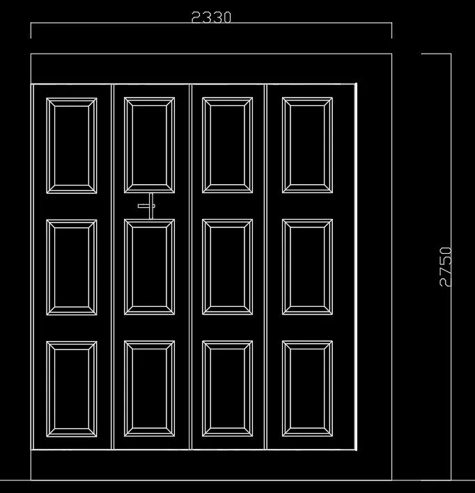
Type B
Block DEFINITION table pops up to the screen.
Give NAME to the Block.
Pick a Point on the Object created as an Insertion Point.
Select objects and choose required object options and behaviour options.
press ok.
BLOCK is created.
RESULT:-
We created the Door Type and then created to BLOCK
DOOR TYPE 2
AIM: -
Create the Door Type 2.
Create the BLOCKS of this Door Type.
PROCEDURE: -
Type 'I'
open INSERT command
Select the block Door_Type 1
Select the Inserton Options
Insertion Point
Scale
Rotation
After providing the details of Insertion options
We can see the block on the screen
Type EXPLODE and select the block.
Now we can edit the Door_type 1 block
Delete all the Small Rectangles From the Door_type 1 block.
Use command FILLET, TRIM AND EXTEND modify tools to get the given figure.
Type B
Block DEFINITION table pops up to the screen.
Give NAME to the Block.
Pick a Point on the Object created as an Insertion Point.
Select objects and choose required object options and behaviour options.
press ok.
BLOCK is created.
RESULT : -
We created the Door Type 2 using BLOCK of Door Type 1
We exploded , edited and then created Block for Door Type 2
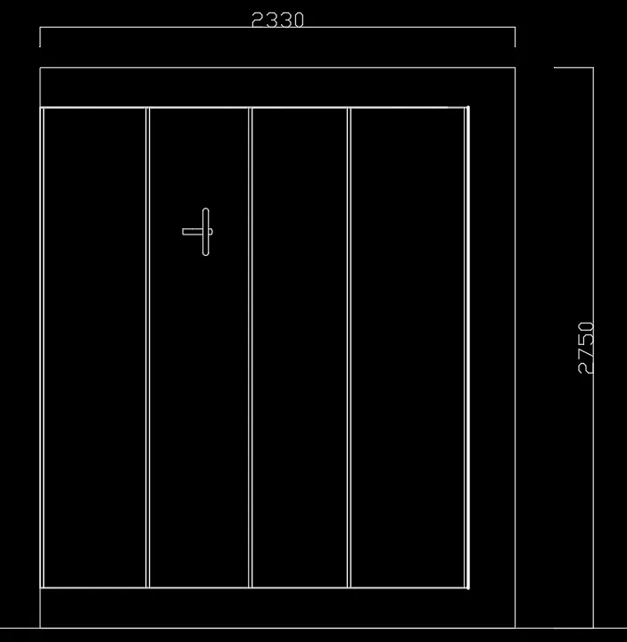
3Q]
AIM: -
Create each symbol as block
Arrange these blocks in the LEGEND.
PROCEDURE: -
Use the METRIC settings as default during START of the AUTOCAD
Set the units to DECIMAL using UNITS command
Draw TABLE with 6 columns and 10 rows.
Give names to the columns as PLAN , NAME as shown in figue.
Draw the shape given in the SYMBOLS LEGEND using Drawing tools.
Type B
Block DEFINITION table pops up to the screen.
Give NAME to the Block.
Pick a Point on the Object created as an Insertion Point.
Select objects and choose required object options and behaviour options.
press ok.
BLOCK is created.
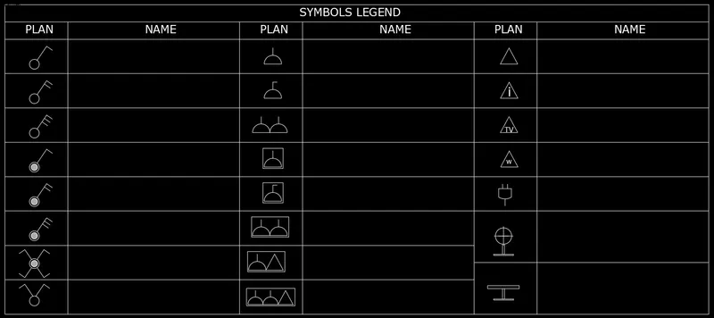
Draw all the shapes provided in the figure and convert them to BLOCKS
After creating BLOCKS,
Go to
RIBBON > INSERT > DATA > FIELD
In Field Category Select OBJECTS option
In field names : select object
OBJECT TYPE: select the BLOCK on the screen
After selecting the BLOCK, All types of Properties related to selected block appears.
In PROPERTIES select Name then press ok.
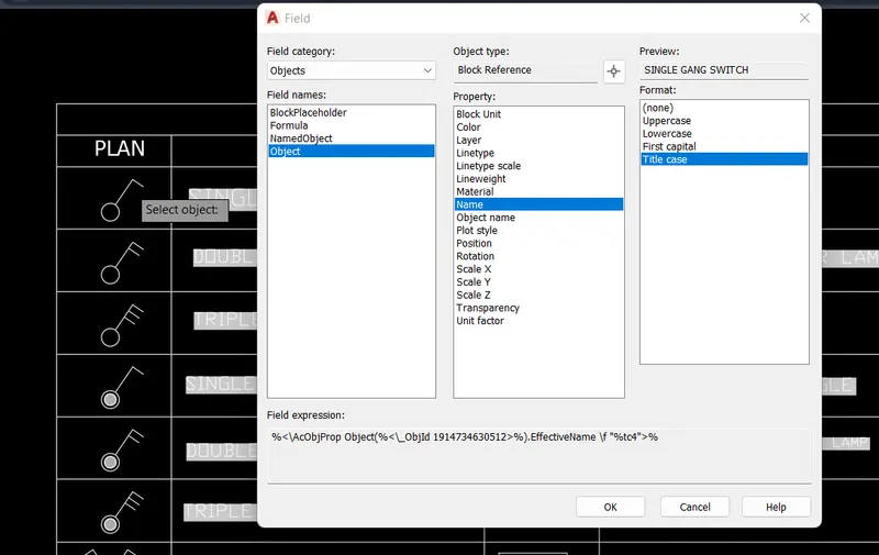
Name of the Block comes on the screen, place at the appropriate position.
Repeat this for all the blocks created
RESULT: -
We created BLOCKS for each symbol and then arranged in the LEGEND.
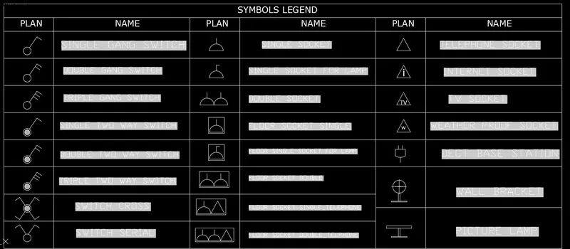
To remove the HATCH part on the NAMES of the symbols we have use EXPLODE command.
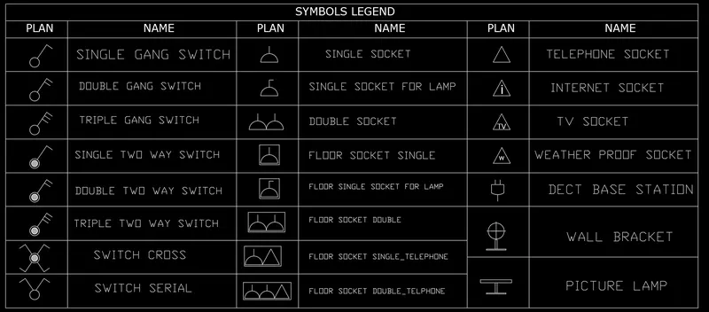
By using EXPLODE command,the link between the BLOCKS and the NAMES is gone.
4Q]
DOOR-D1
AIM: -
Create the Door Type-D1 as a BLOCK.
PROCDURE: -
Use the IMPERIAL settings as default during START of the AUTOCAD.
Set the units to ENGINEERING using UNITS command.
Select RECTANGLE command
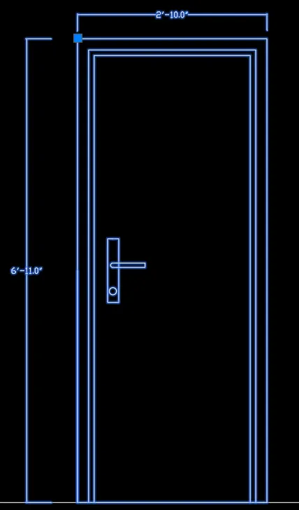
Draw RECTANGLE of lengh 2'-10" units and width 6'-11" units
Select OFFSET modify tool and provide offset distance as 1" units to the Rectangle.
Select OFFSET modify tool and provide offset distance as 1" units to the Rectangle.
Select OFFSET command and provide offset distance as 0.5" units to the previous Rectangle.
Select TRIM command and select all the Rectangles drawn and trim the bottom Length (2'-10")line of the Rectangles.
Draw handle to the Door using Drawing Tools.
Type B
Block DEFINITION table pops up to the screen.
Give NAME to the Block.
Pick a Point on the Object created as an Insertion Point.
Select objects and choose required object options and behaviour options.
press ok.
RESULT: -
DOOR-D2
AIM: -
Create the Door Type-D2 as a BLOCK.
PROCEDURE: -
Type 'I'
open INSERT command
Select the block Door_1
Select the Inserton Options
Insertion Point
Scale
Rotation
After providing the details of Insertion options
We can see the block on the screen
Type EXPLODE and select the block.
Now we can edit the Door_1 block
Draw Rectangle of length 3'-4" units.
Use EXTEND command to extend the remaining lines.
Draw Rectangles using offset distance as 0.5 units. for 3 times with in the drawn Rectangle.
Select TRIM command and select all the Rectangles drawn and trim the bottom Length (2'-10")line of the Rectangles.
Select RECTANGLE command, draw Rectangle with dimensions of length 7.5" units and width 7.5" units.
Select ARRAY coomand
Select Rectangular Array and select object
Provide details to the array and draw 4 x 3 matrix of small Rectangles of total 12 Rectangles.
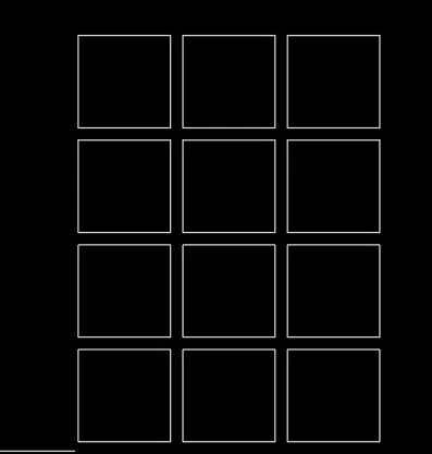
Arrange this Array in the Available space
Select EXPLODE command and explode all the small Rectangles.
Select OFFSET command with offset distance as 0.25" units and draw offset within these each small Rectangles.
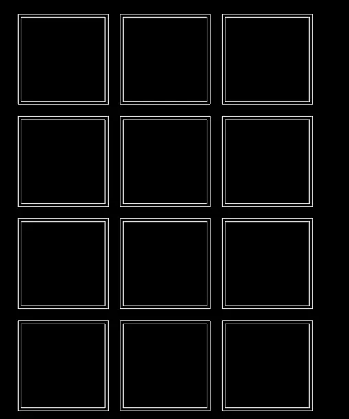
Close all the Rectangles below this array.
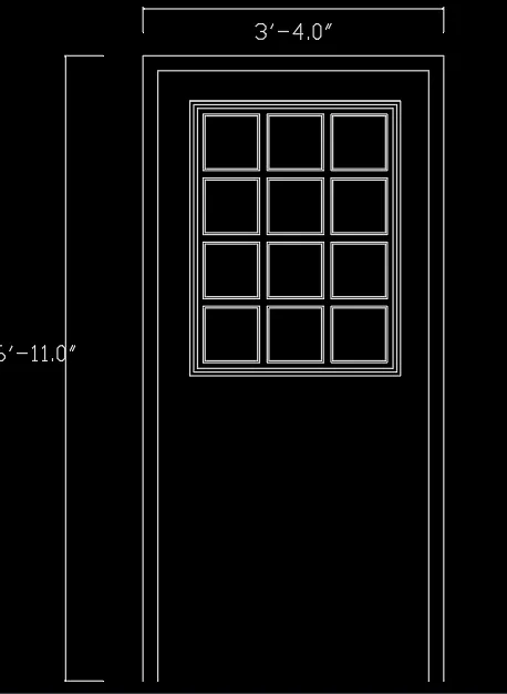
Draw small circle below this at midpint of length 3'4" units below the drawn figure.
With in the available space draw Rectangles with OFFSETs.
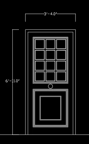
Type B
Block DEFINITION table pops up to the screen.
Give NAME to the Block.
Pick a Point on the Object created as an Insertion Point.
Select objects and choose required object options and behaviour options.
press ok.
RESULT: -
We created Door_2 block
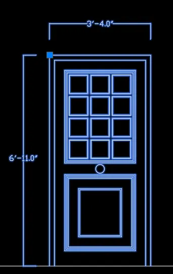
DOOR_D3
AIM: -
Create the Door Type-D3 as a BLOCK.
PROCEDURE: -
Select RECTANGLE command
Draw rectangle with size 2'-9" x 6'-11" units.
Select OFFSET command with offset distance 0.5" units to this Rectangle.
Select OFFSET command with offset distance 2" units to this rectangle.
Select OFFSET command with offset distance 0.5" units to this Rectangle.
Select OFFSET command with offset distance 0.5" units to this Rectangle.
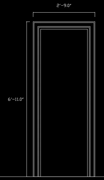
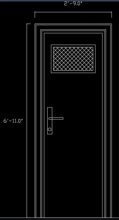
Draw Small Rectangle with OFFSEt of 0.25" units. inside these Rectangles
Hatch the small Rectangle.
Provide handle at the appropriate location.
Type B
Block DEFINITION table pops up to the screen.
Give NAME to the Block.
Pick a Point on the Object created as an Insertion Point.
Select objects and choose required object options and behaviour options.
press ok.
RESULT:-
DOOR_D4
AIM: -
Create the Door Type-D4 as a BLOCK.
PROCEDURE: -
Type 'I'
open INSERT command
Select the block Door_D2
Select the Inserton Options
Insertion Point
Scale
Rotation
After providing the details of Insertion options
We can see the block on the screen
Type EXPLODE and select the block.
Now we can edit the Door_D2 block.
Select ARC command with START, END , DIDRETION option.
Draw Arc to the Rectangle and provide OFFSETS
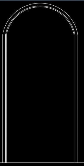
Draw ARC to the small Rectangles Array start point as 1st corner of the rectangle and last corner of the 3rd recangle and direction to the upside.
Use EXTEND command to close rectangles corners to the ARC.
Provide OFFSET to all Rectangles
Join Arcs and Rectangle legs using EXTEND command.
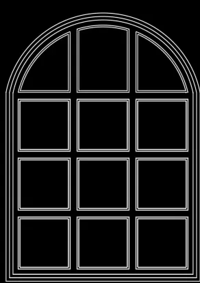
Copy the Rectangular Array and paste below the circle.
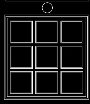
Delete one row of the Rectangular Array to form 3 x 3 matrix of rectangles.
Adjust the Rectangles within the available space.
Type B
Block DEFINITION table pops up to the screen.
Give NAME to the Block.: DOOR_D4
Pick a Point on the Object created as an Insertion Point.
Select objects and choose required object options and behaviour options.
press ok.
RESULT:-
We created Door_D4 block.
DOOR_D5
AIM: -
Create the Door Type-D4 as a BLOCK.
PROCEDURE: -
Type 'I'
open INSERT command
Select the block Door_D2
Select the Inserton Options
Insertion Point
Scale
Rotation
After providing the details of Insertion options
We can see the block on the screen
Type EXPLODE and select the block.
Now we can edit the Door_D2 block.
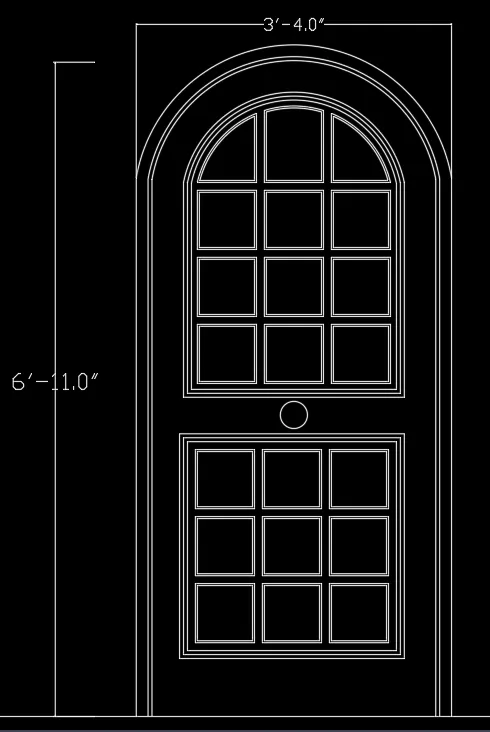
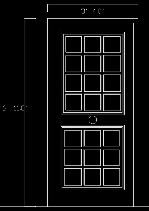
Delete the bottom part of the DOOR_D2
Copy the Rectangle Array and Paste below the circle.
Delete the one row to get 3 x 3 matrix of rectangle.
Adjust the Rectangles within the available space.
Type B
Block DEFINITION table pops up to the screen.
Give NAME to the Block.: DOOR_D5
Pick a Point on the Object created as an Insertion Point.
Select objects and choose required object options and behaviour options.
press ok.
RESULT: -
We created the DOOR_D5 block.
DOOR_D6
AIM: -
Create the Door Type-D6 as a BLOCK.
PROCEDURE: -
Type 'I'
open INSERT command
Select the block Door_D4
Select the Inserton Options
Insertion Point
Scale
Rotation
After providing the details of Insertion options
We can see the block on the screen
Type EXPLODE and select the block.
Now we can edit the Door_D4 block.
Type 'I'
open INSERT command
Select the block Door_D2
Select the Inserton Options
Insertion Point
Scale
Rotation
After providing the details of Insertion options
We can see the block on the screen
Type EXPLODE and select the block.
Now we can edit the Door_D2 block.
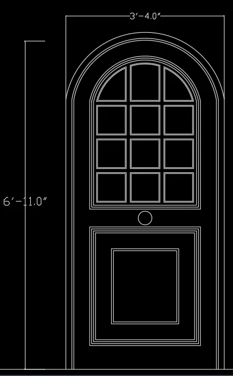
Delete the bottom part of the Door_D4
Copy the bottom of the Door_D2
Paste the copied part to the Door_D4
Type B
Block DEFINITION table pops up to the screen.
Give NAME to the Block.: DOOR_D6
Pick a Point on the Object created as an Insertion Point.
Select objects and choose required object options and behaviour options.
press ok.
RESULT: -
We created DOOR_D6 block by editing D2 and D4 blocks.
5Q]
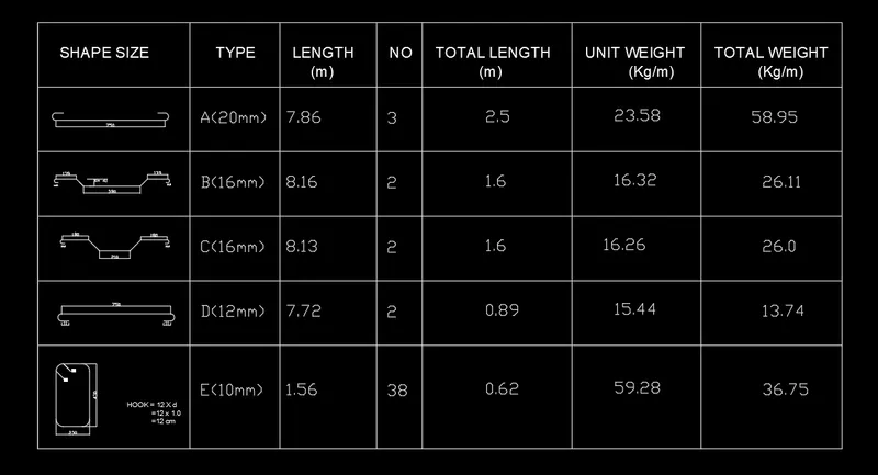
AIM: -
Create each shape as a block given in figure.
Use the Text and Attributes wherever required.
PROCEDURE: -
Use the METRIC settings as default during START of the AUTOCAD.
Set the units to DECIMAL using UNITS command.
Select Line command
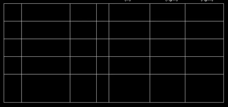
Draw Table of 5 Rows and 7 Columns.
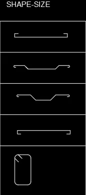
Select Line command and draw all the shapes given in the figure.
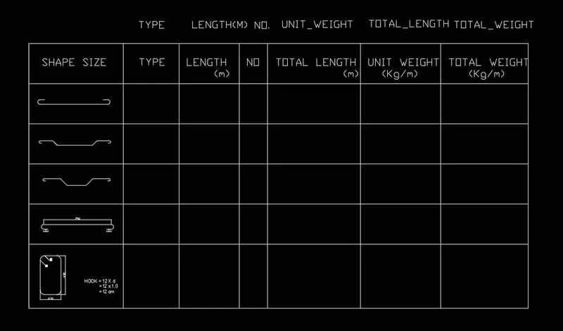
Select ANNONTATE in Ribbon
Under TEXT dialogue box
Choose Multiline Text tool
Using MTEXT label the details
Select command: ‘_STYLE
Create new style with Font name - Arial and Font Style – Regular
Set current.
Type Text in one of the rows.
TYPE
LENGTH
NO
TOTAL LENGTH(m)
UNIT WEIGHT(Kg/m)
TOTAL WEIGHT(Kg)
Create ATTRIBUTES for the mentioned TEXTS
Select INSERT > BLOCK DEFINITION > DEFINE ATTRIBBUTES
Attribute Table pops up on the screen.
In MODE tick the LOCK POSITION, PRESET options.
INSERTION POINT: Specify on the screen
ATTRIBUTE:
Tag: Type
Prompt: What is the type?
Default: A(20mm)
TEXT SETTINGS:
Justification: Left
Text Style:
Text Height:
After entering all the required data press OK.
Place the Attribute that we created under the TYPE column.
After finishing creating ATTRIBUTE for TYPE
Repeat the same process to create ATTRIBUTE for the rest of the TEXTS.
Place all the created attributes under their respective column.
Copy all the ATTRIBUTES created and paste in the respective Rows.
Create blocks for each shape.
Type "B "
Open BLOCK Definition box
Give NAME to the Block.
Pick a Point on the Object created as an Insertion Point.
Select objects as shape and respective ATTRIBUTES and choose required object options and behaviour options.
press ok.
After converting to Block
The TEXT what we typed in the ATTRIBUTE Default box DISPLAYS IN THE BLOCK.
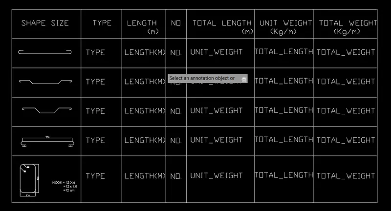
Edit Each ATTRIBUTE for each shape type the data provided in the figure.
RESULT: -
WE created BLOCKS for each shape and assigned ATTRIBUTES to each shape and entered the data as given in the figure.