Creating Bar Bending schedule, Different Door types, and Creation of standard drawing templates using AutoCad
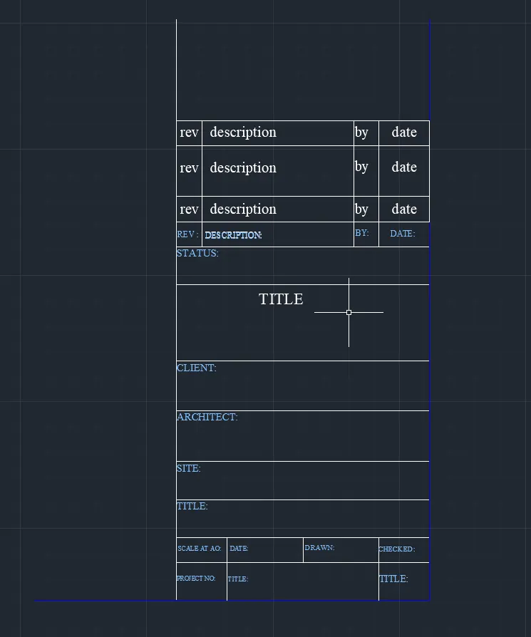
- AIM: To create the template as shown in the figure
- PROCEDURE:
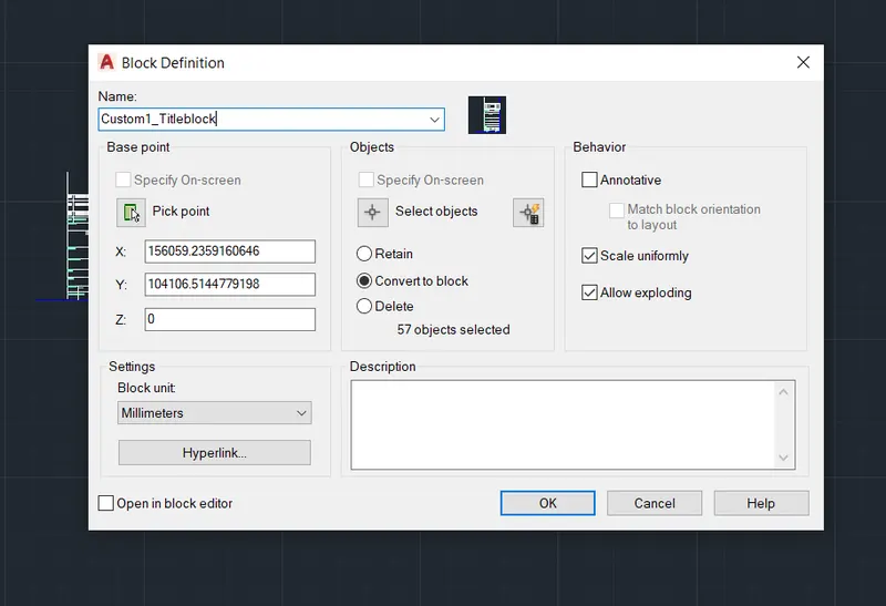
- Creation of Custom1_Titleblock
- In the command type ''UN'' and select the units and scale
- Type offset distance in the command box
- Select the object the to offset
- Select the text tool from the ribbon tab and enter the required text
- Specify the next point to enter the text]
- From ribbon tool seledt the linew tool specify the starting point
- Draw the line required length
- Select the layer from the option and select the layer option
- Enter the required layer name select the line type and color
- Now select text tool from ribbon
- Select the single line text option
- Specify the next point to text
- From the ribbon tab and selext the line tool
- Specify the starting point from bottom and draw a vertical line
- From spacebar to reintiate the previous command that is line command
- Draw a vertical line as per template
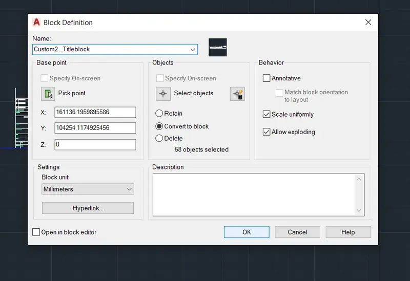
- Creation of Custom2_Title block
- From ribbon tab select the line tool
- Specify starting point using cursor
- Draw a line of required length and press enter
- Select the layer setting from ribbon tab
- From layer settings tab select the layer option
- Enter the required layer name and select the line type and colour
- Set the created layer as current layer
- From ribbon tab ,select the line tool
- Specify the starting point using cursor
- Draw the line of required length
- Draw the required the length and press enter
- Select the text tool from ribbon tab and press enter
- Select the line text option
- Now enter the required text
- Specify the next point to enter the text
- RESULT

- RESULT
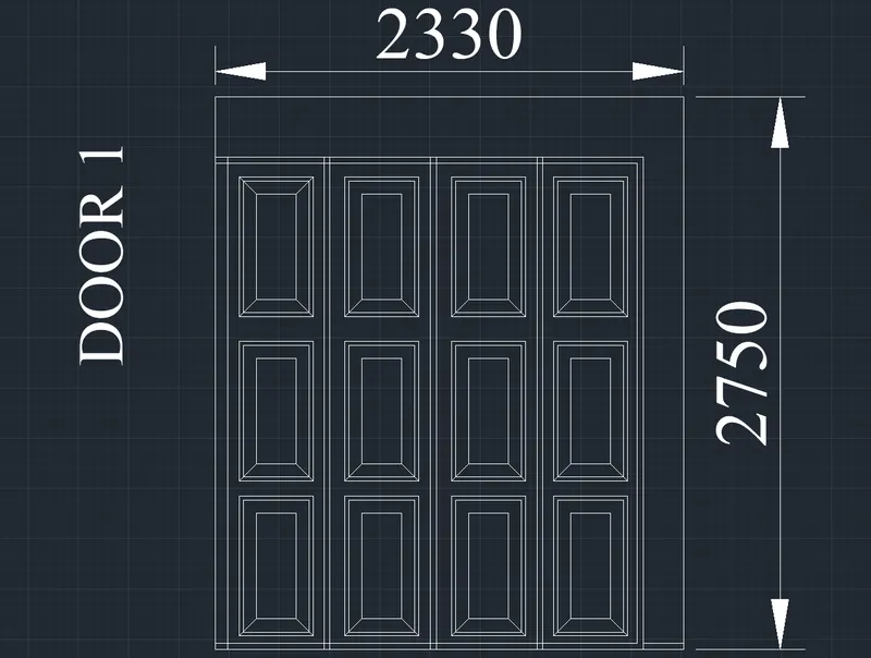
- AIM: To create the door type for ware house as shown in the figure
- PROCEDURE:
- In the command type ''UN'' and select the units and scale
- Type offset distance in the command box
- Select the object the to offset
- Select the text tool from the ribbon tab and enter the required text
- Select the layer from the option and select the layer option
- Enter the required layer name select the line type and color
- Now select text tool from ribbon
- Select the single line text option
- Specify the next point to text enter the required text
- Select the ''rec'' and specify the rectangle of dimension 2330 X 2750
- Type offset and select the distance offset the line inword
- create the rectangle and of 400 X 700 and offset into the inward
- Copy the rectangle and placed it into the required position
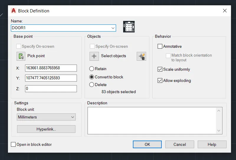
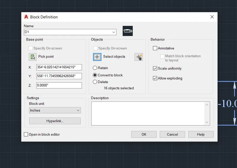
- create the block ''DOOR 1''
- RESULT
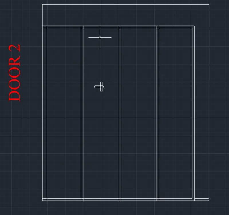
- Create the ''DOOR 2 '' as shown iin the figure
- PROCEDURE
- Select the outer layer of ''door1'' and copy it
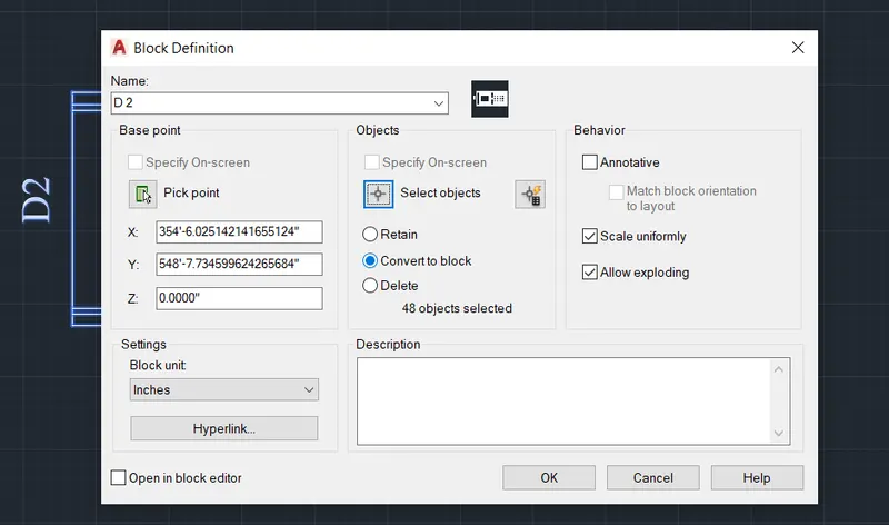
- Create the block of '' door2'' by by picking the point and by selecting the entire figure
- Created block will be shown in the drawing
- RESULT
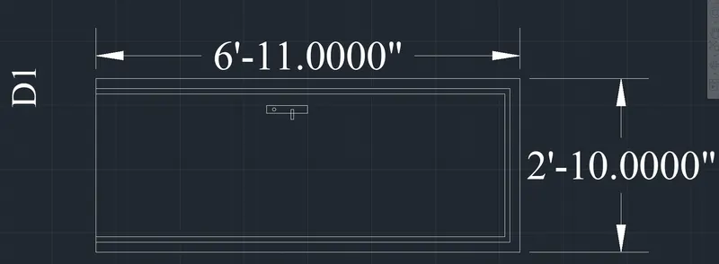
- AIM: To create the drawing as shown in the figure
- PROCEDURE:
- In the command type ''UN'' and select the units and scale
- Type offset distance in the command box
- Select the object the to offset
- Select the text tool from the ribbon tab and enter the required text
- Specify the next point to enter the text]
- From ribbon tool seledt the linew tool specify the starting point
- Draw the line required length
- Select the layer from the option and select the layer option
- Enter the required layer name select the line type and color
- Now select text tool from ribbon
- Select the single line text option
- Type offset in the command box and press enter
- Select the object to offset
- Repeat the offset command as per required dimension
- RESULT
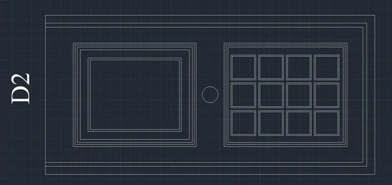
- Create the ''D2'' as as shown in the figure
- copy the outer lay and move it used it for ''d2''
- Select the offset and give the proper offset
- Create the rectangle 30 X 25 and insert into the door
- Offset the reactqangle as per requirement
- Select the circle tool from ribbon and place it in the ribbon
- Crate another rectangle and place it in the ''d2'' and insert the rectangle of 6 X 6 using command array
- RESULT
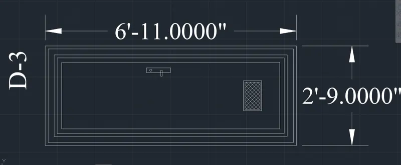
- CREATE THE ''D3'' AS SHOWN IN T HE FIGURE
- Copy the outer layer of previous rectangle and used it for ''D3''
- offset the rectangle inwordly as per requirement
- Insert the door lock
- Create the rectangle and insert it into the door and using hatch command hatch the reactangle
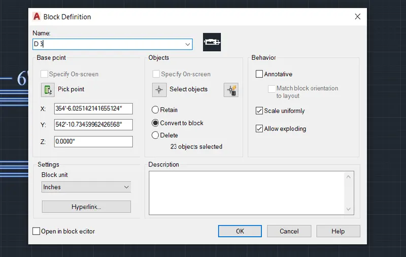
- Using block command create the block of ''D2''
- RESULT
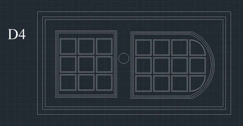
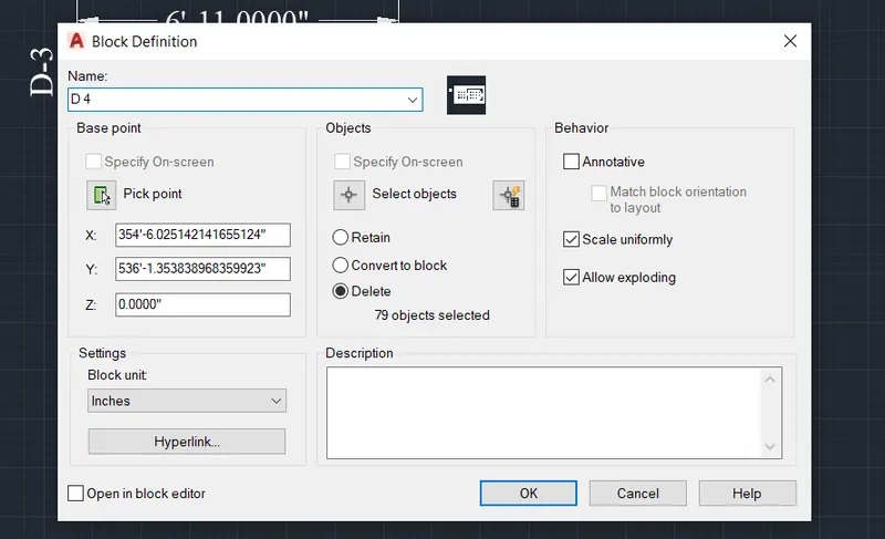
- Create the ''door 4'' as shown in the figure
- Copy the outer array of previous drawing
- offset the rectangle inwordly as per requirement
- create the circle as per requirment and plac it in the door 4
- using fillet command create the half circle as per requirement
- copy the inword rectangle from the previous drawing and place it in the door4
- RESULT
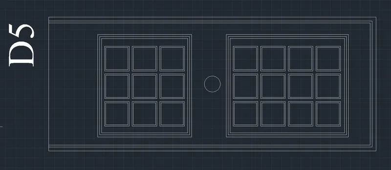
- Create the d-5 drawing as shown in the figure
- Copy the outer array of previous drawing
- offset the rectangle inwordly as per requirement
- create the circle as per requirment and plac it in the door 5
- Copy the inword rectangle from the d2 and place it in the d5
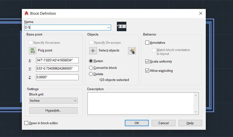
- Create the block ''d5''
- RESULT
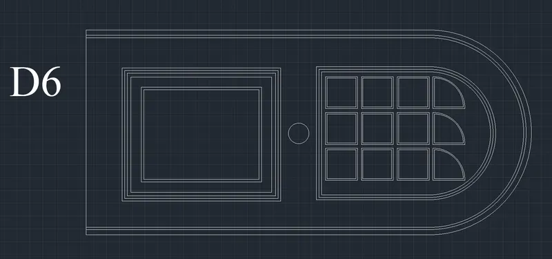
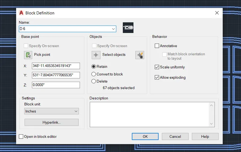
- CREATE THE ''D6'' AS SHOWN IN THE FIGURE
- Copy the outer array of previous drawing
- offset the rectangle inwordly as per requirement
- create the circle as per requirment and plac it in the door 4
- using fillet command create the half circle as per requirement
- copy the inword rectangle from the previous drawing and place it in the door
- RESULT
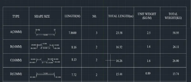
- CREATE THE TABLE AS SHOWN IN THE FIGURE
- Using the command table create thew table of column of 7 and row of 6 numbers
- Insert the text in the table as shown in the figure
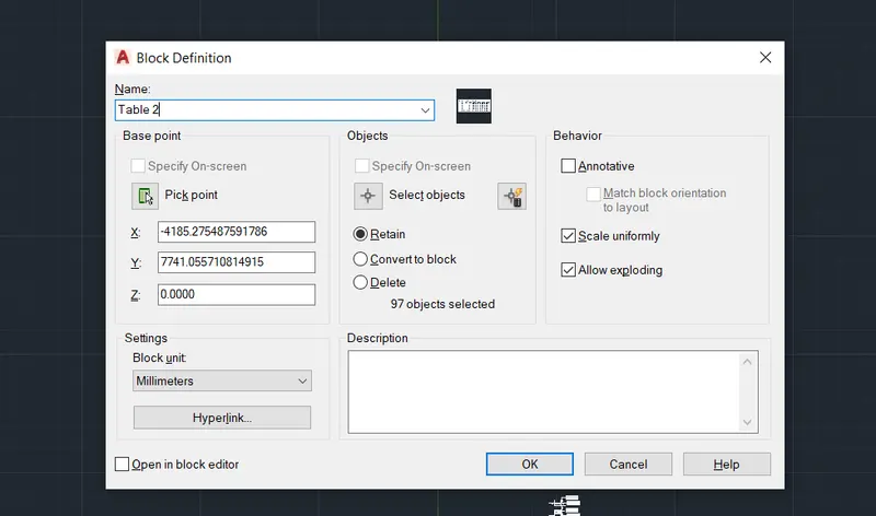
- Create the block named qas ''Table 2 ''
- RESULT