Creating Bar Bending schedule, Different Door types, and Creation of standard drawing templates using AutoCad
Challenge 8: Creating Bar Bending schedule, Different Door types, and Creation of standard drawing templates using AutoCad
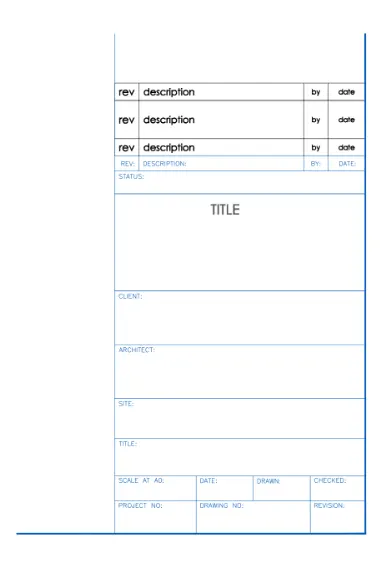
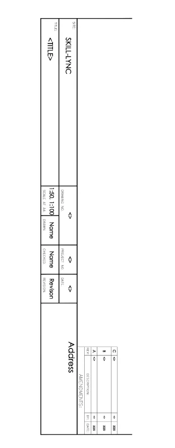
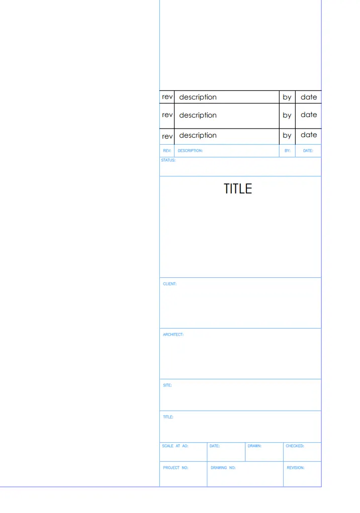
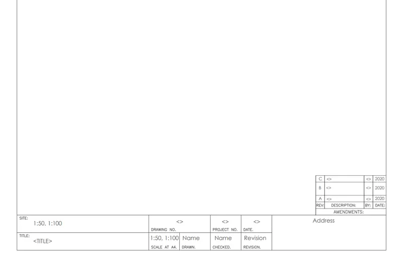
1. Create the templates as shown in Figures. Take the size of the title block as per industry standards or you can assume it as per the size of the paper. Use text and attributes wherever required. After creating the title block you need to save it as a block with names: Custom1_titleblock and Custom2_titleblock, respectively.
AIM
To create the templates as shown in figures, use text and attributes wherever required.
INTRODUCTION
In AutoCAD, a block is a collection of objects that are combined into a single named object. To use this function, first create objects and then open 'Block Definition' using command 'B/BLOCK'.
PROCEDURE
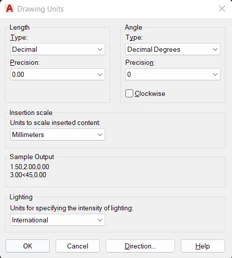
Open the AutoCAD Application and create a new AutoCAD file with imperial settings. Set the length type in 'Decimal' and precision (0.00), insertion scale to 'Millimeters' in the Drawing Units and press OK. Set limits and zoom all.
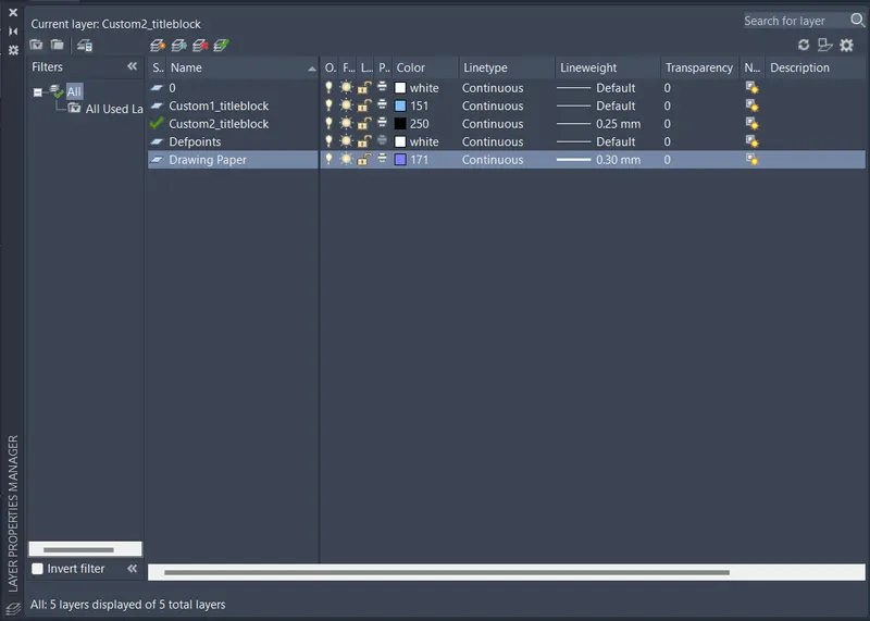
Layers are created, the different layers used in this project is shown below
Part A: Custom1_titleblock
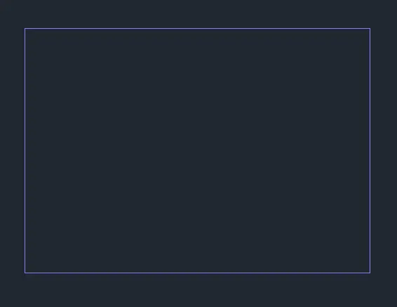
1. Draw the drawing paper (A3 paper)
- Type 'LA' in the command line and enter to get layers
- Create a new layer 'Drawing Paper' with lineweight "0.30mm"
- Type 'REC' in the command line and enter to get rectangle
- Create a rectangle of size 420mmx297mm
- Select the rectangle, type 'EXPLODE' and enter
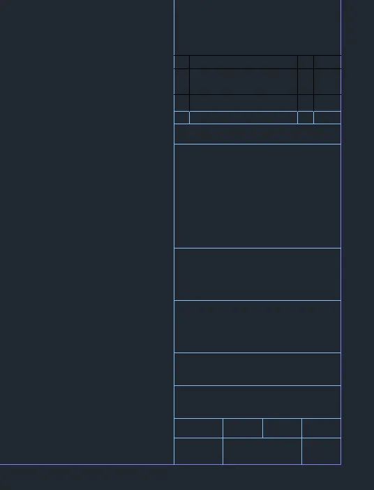
2. Draw the objects to create title block
- Type 'LA' in the command line and enter to get layers
- Create a new layer 'Custom1_titleblock'
- Type 'OFF' in the command line and enter to get offset tool
- Offset 12mm from the bottom line in the y direction
- Offset 9mm from the previous line in the y direction
- Offset 15mm from the previous line in the y direction
- Offset 15mm from the previous line in the y direction
- Offset 24mm from the previous line in the y direction
- Offset 24mm from the previous line in the y direction
- Offset 48mm from the previous line in the y direction
- Offset 9mm from the previous line in the y direction
- Offset 6mm from the previous line in the y direction
- Offset 7.5mm from the previous line in the y direction
- Offset 12mm from the previous line in the y direction
- Offset 6mm from the previous line in the y direction
- Offset 12mm from the rightside line in the -x direction
- Offset 7.5mm from the previous line in the -x direction
- Offset 6mm from the previous line in the -x direction
- Offset 50mm from the previous line in the -x direction
- Offset 7mm from the previous line in the -x direction
- Offset 18mm from the rightside line in the -x direction
- Offset 18mm from the previous line in the -x direction
- Offset 18mm from the previous line in the -x direction
- Offset 22.5mm from the previous line in the -x direction
- Type 'TR' in the command line and enter to get trim tool
- Trim all unnecessary lines to get the desired design
- Select some lines and change colours to "0,0,0" as per the figure given
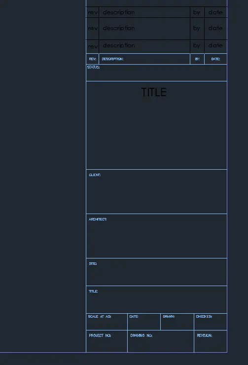
3. Insert texts
- Type 'MTEXT' in the command line and enter to get multi line text
- Type text wherever required as per the design
- Different fonts are used with different heights
- Select some texts and give colours "0,0,0" as per the figure given
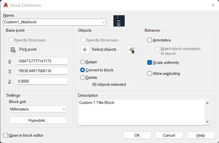
4. Create block
- Type 'B' in the command line and enter to get block definition
- Name: 'Custom1_titleblock'
- Base point: Pick point from the screen according to the design
- Objects: Select ojects from the screen, click 'Convert to block'
- Behavior: Tick 'Scale uniformly'
- Settings: Block unit as 'Millimeters'
- Description: 'Custom 1 Title Block'
- Press OK
Part B: Custom2_titleblock
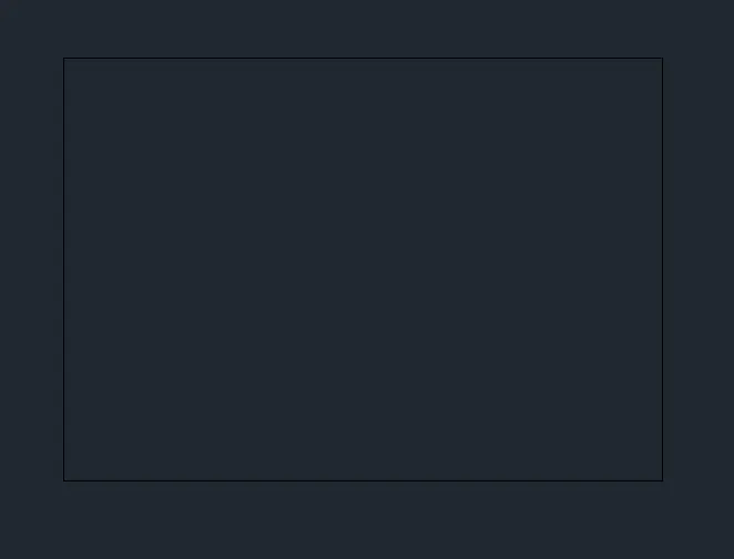
1. Draw the drawing paper (A3 paper)
- Select 'Drawing Paper' layer
- Type 'REC' in the command line and enter to get rectangle
- Create a rectangle of size 420mmx297mm
- Select the rectangle and change colours to "0,0,0" as per the figure given
- Select the rectangle, type 'EXPLODE' and enter
2. Draw the objects to create title block
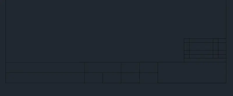
- Type 'LA' in the command line and enter to get layers
- Create a new layer 'Custom2_titleblock'
- Type 'OFF' in the command line and enter to get offset tool
- Offset 20mm from the bottom line in the y direction
- Offset 20mm from the previous line in the y direction
- Offset 7.5mm from the previous line in the y direction
- Offset 7.5mm from the previous line in the y direction
- Offset 7.5mm from the previous line in the y direction
- Offset 15mm from the previous line in the y direction
- Offset 7.5mm from the previous line in the y direction
- Offset 15mm from the rightside line in the -x direction
- Offset 15mm from the previous line in the -x direction
- Offset 45mm from the previous line in the -x direction
- Offset 15mm from the previous line in the -x direction
- Offset 130mm from the rightside line in the -x direction
- Offset 35mm from the previous line in the -x direction
- Offset 35mm from the previous line in the -x direction
- Offset 35mm from the previous line in the -x direction
- Offset 35mm from the previous line in the -x direction
- Type 'TR' in the command line and enter to get trim tool
- Trim all unnecessary lines to get the desired design
3. Insert texts
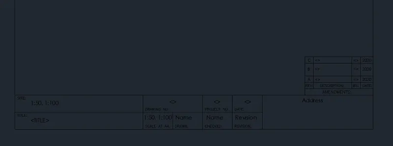
- Type 'MTEXT' in the command line and enter to get multi line text
- Type text wherever required as per the design
- Different fonts are used with different heights
4. Create block
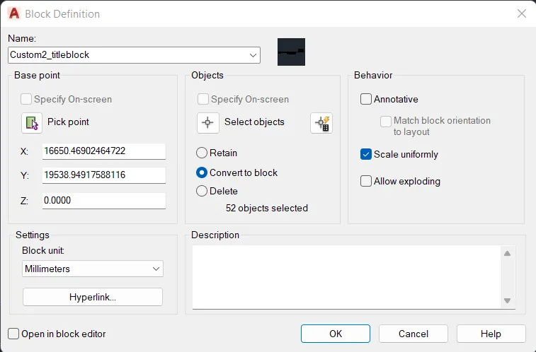
- Type 'B' in the command line and enter to get block definition
- Name: 'Custom2_titleblock'
- Base point: Pick point from the screen according to the design
- Objects: Select ojects from the screen, click 'Convert to block'
- Behavior: Tick 'Scale uniformly'
- Settings: Block unit as 'Millimeters'
- Description: 'Custom 2 Title Block'
- Press OK
RESULT
The templates are created as shown in figures. All dimensions are in 'mm'
Part A: Custom1_titleblock
Part B: Custom2_titleblock
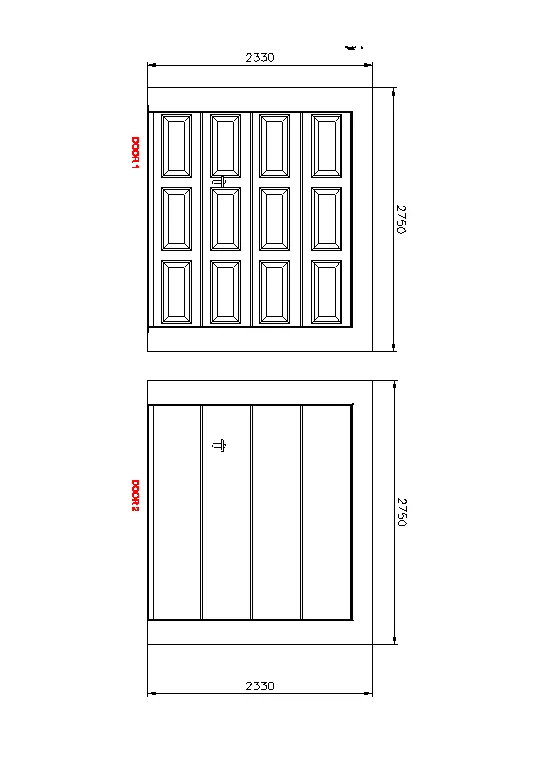
2. Create the doors type for warehouse as shown in the Figure. You need to create each door type as per standard size or given dimensions. Create the blocks of this door type after creating them.
AIM
To create the door types for warehouse as shown in the figure with given dimensions
INTRODUCTION
In AutoCAD, a block is a collection of objects that are combined into a single named object. To use this function, first create objects and then open 'Block Definition' using command 'B/BLOCK'.
PROCEDURE
Open the AutoCAD Application and create a new AutoCAD file with imperial settings. Set the length type in 'Decimal' and precision (0.00), insertion scale to 'Millimeters' in the Drawing Units and press OK. Set limits and zoom all.
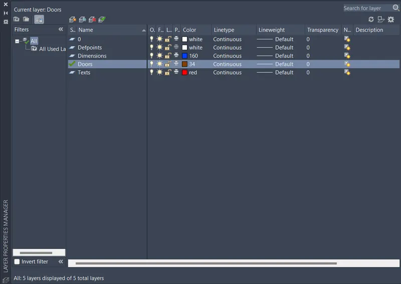
Layers are created, the different layers used in this project is shown below
Part A: Door 1
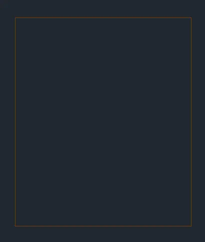
1. Create a door outline
- Type 'LA' in the command line and enter to get layers
- Create a new layer 'Doors'
- Type 'REC' in the command line and enter to get rectangle
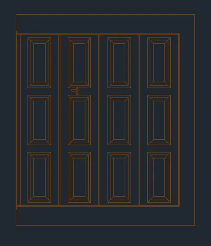
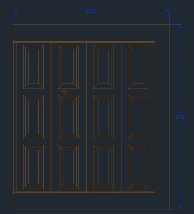
- Draw a rectangle of size 2330mmx2750mm
- Select the rectangle and type 'EXPLODE'
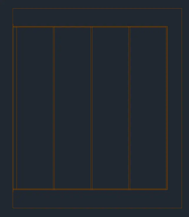
2. Create door parts inside door
- Type 'OFF' in the command line and enter to get offset tool
- Offset 250mm from the bottom line in the y direction
- Offset 5mm from the previous line in the y direction
- Offset 10mm from the previous line in the y direction
- Offset 2220mm from the previous line in the y direction
- Offset 10mm from the previous line in the y direction
- Offset 5mm from the previous line in the y direction
- Offset 250mm from the previous line in the y direction
- Offset 200mm from the rightside line in the -x direction
- Offset 5mm from the previous line in the -x direction
- Offset 10mm from the previous line in the -x direction
- Offset 500mm from the previous line in the -x direction
- Offset 20mm from the previous line in the -x direction
- Offset 500mm from the previous line in the -x direction
- Offset 20mm from the previous line in the -x direction
- Offset 500mm from the previous line in the -x direction
- Offset 20mm from the previous line in the -x direction
- Offset 500mm from the previous line in the -x direction
- Offset 50mm from the previous line in the -x direction
- Offset 5mm from the previous line in the -x direction
- Type 'TR' in the command line and enter to get trim tool
- Trim all unnecessary lines to get the desired design
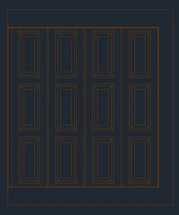
3. Create door panels inside door
- Type 'REC' in the command line and enter to get rectangle
- Draw a rectangle of size 300mmx650mm
- Type 'OFF' in the command line and enter to get offset tool
- Offset 30mm from the rectangle
- Offset 45mm from the new offset rectangle
- Type 'L' in the command line and enter to get line
- Draw lines from corner of outside rectangle to corner of inside rectangle for 4 sides
- Type 'CO' in the command line and enter to get copy tool
- Select the rectangle and place it according to the design
4. Create a door knob
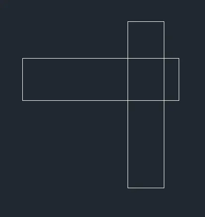
- Type 'REC' in the command line and enter to get rectangle
- Draw a rectangle of size 20mmx100mm
- Draw a rectangle of size 100mmx25mm
- Place these to rectangle intersecting each other just above the middle of both the rectangle perpendularly
- Type 'F' in the command line and enter to get fillet tool
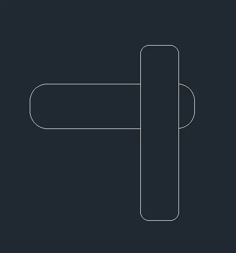
- Select the rectangle 20mmx100mm, fillet 5mm radius on every corner
- Select the rectangle 100mmx25mm, fillet 10mm radius on every corner
- Type 'TR' in the command line and enter to get trim tool
- Trim all unnecessary lines to get the desired design
- Type 'CO' in the command line and enter to get copy tool
- Select the drawn door knob and place it inside the door
5. Insert dimensions
- Type 'LA' in the command line and enter to get layer properties
- Create a new layer "Dimensions"
- Type 'DIMSTY' in the command line and enter to get dimension style settings
- Dimension Style is created as New, the settings are shown below
- In Lines, Fixed length extension lines is given as 100mm.
- In Symbols and Arrows, Arrow size is given as 50mm.
- In Text, Text height is given as 50mm
- In Fit, Overall scale is given as 1
- Type 'DIM' in the command line and enter to get dimension line
- Mark all necessary dimensions
6. Insert text
- Type 'LA' in the command line and enter to get layer properties
- Create a new layer "Texts"
- Type 'MTEXT' in the command line and enter to get multi line text
- Type text wherever required as per the plan
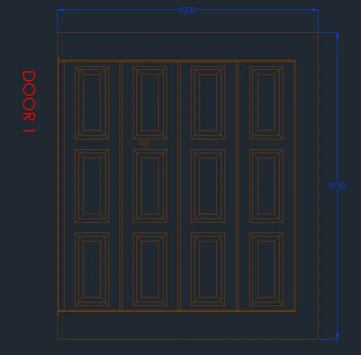
7. Create block
- Turn off 'Dimensions' layer
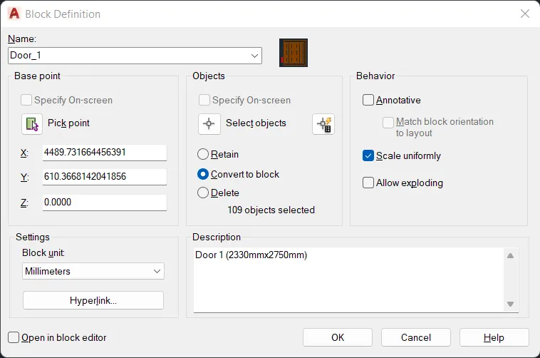
- Type 'B' in the command line and enter to get block definition
- Name: 'Door_1'
- Base point: Pick point from the screen according to the design
- Objects: Select ojects from the screen, click 'Convert to block'
- Behavior: Tick 'Scale uniformly'
- Settings: Block unit as 'Millimeters'
- Description: 'Door 1 (2330mmx2750mm)'
- Press OK
Part B: Door 2
1. Create a door outline
- Select 'Doors' layer
- Type 'REC' in the command line and enter to get rectangle
- Draw a rectangle of size 2330mmx2750mm
- Select the rectangle and type 'EXPLODE'
2. Create door parts inside door
- Type 'OFF' in the command line and enter to get offset tool
- Offset 250mm from the bottom line in the y direction
- Offset 5mm from the previous line in the y direction
- Offset 10mm from the previous line in the y direction
- Offset 2220mm from the previous line in the y direction
- Offset 10mm from the previous line in the y direction
- Offset 5mm from the previous line in the y direction
- Offset 250mm from the previous line in the y direction
- Offset 200mm from the rightside line in the -x direction
- Offset 5mm from the previous line in the -x direction
- Offset 10mm from the previous line in the -x direction
- Offset 500mm from the previous line in the -x direction
- Offset 20mm from the previous line in the -x direction
- Offset 500mm from the previous line in the -x direction
- Offset 20mm from the previous line in the -x direction
- Offset 500mm from the previous line in the -x direction
- Offset 20mm from the previous line in the -x direction
- Offset 500mm from the previous line in the -x direction
- Offset 50mm from the previous line in the -x direction
- Offset 5mm from the previous line in the -x direction
- Type 'TR' in the command line and enter to get trim tool
- Trim all unnecessary lines to get the desired design
3. Create a door knob
- Type 'REC' in the command line and enter to get rectangle
- Draw a rectangle of size 20mmx100mm
- Draw a rectangle of size 100mmx25mm
- Place these to rectangle intersecting each other just above the middle of both the rectangle perpendularly
- Type 'F' in the command line and enter to get fillet tool
- Select the rectangle 20mmx100mm, fillet 5mm radius on every corner
- Select the rectangle 100mmx25mm, fillet 10mm radius on every corner
- Type 'TR' in the command line and enter to get trim tool
- Trim all unnecessary lines to get the desired design
- Type 'CO' in the command line and enter to get copy tool
- Select the drawn door knob and place it inside the door
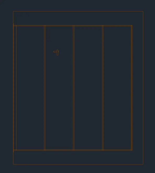
4. Insert dimensions
- Select "Dimensions" layer
- Type 'DIMSTY' in the command line and enter to get dimension style settings
- Dimension Style is created as New, the settings are shown below
- In Lines, Fixed length extension lines is given as 100mm.
- In Symbols and Arrows, Arrow size is given as 50mm.
- In Text, Text height is given as 50mm
- In Fit, Overall scale is given as 1
- Type 'DIM' in the command line and enter to get dimension line
- Mark all necessary dimensions
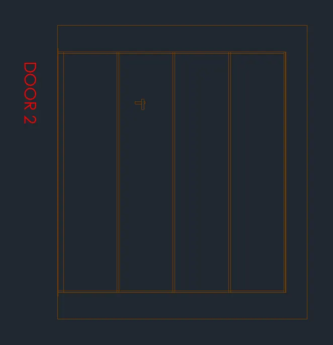
5. Insert text
- Select "Texts" layer
- Type 'MTEXT' in the command line and enter to get multi line text
- Type text wherever required as per the plan
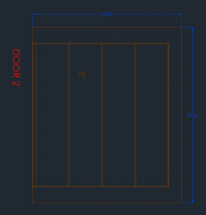
6. Create block
- Turn off 'Dimensions' layer
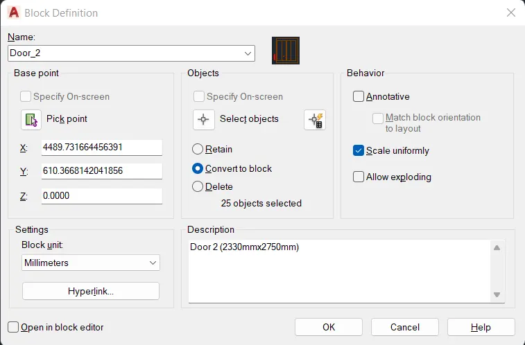
- Type 'B' in the command line and enter to get block definition
- Name: 'Door_2'
- Base point: Pick point from the screen according to the design
- Objects: Select ojects from the screen, click 'Convert to block'
- Behavior: Tick 'Scale uniformly'
- Settings: Block unit as 'Millimeters'
- Description: 'Door 2 (2330mmx2750mm)'
- Press OK
RESULT
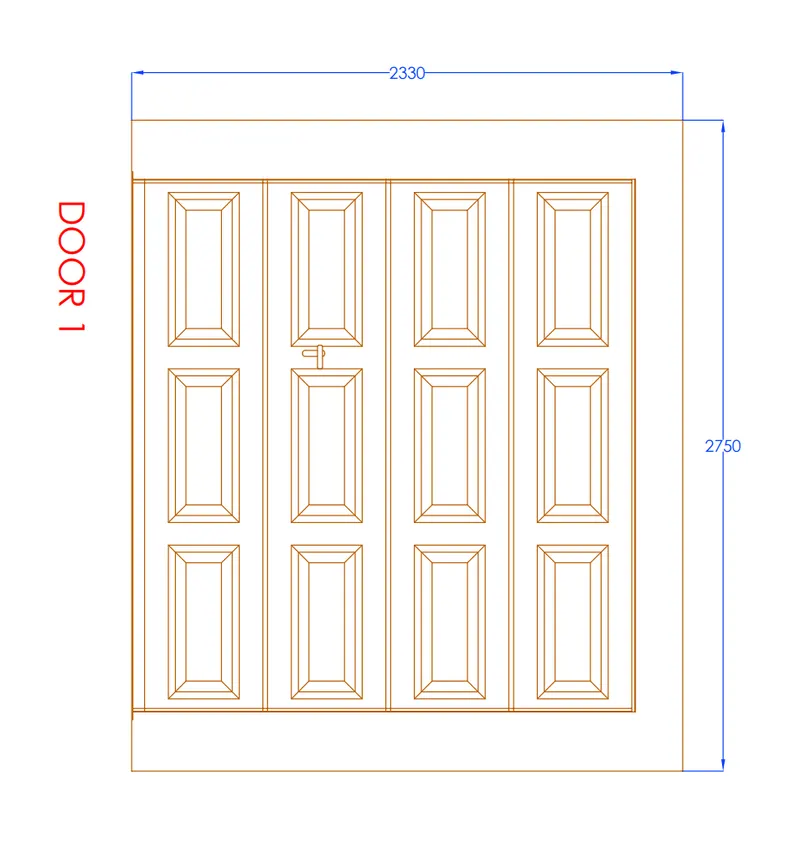
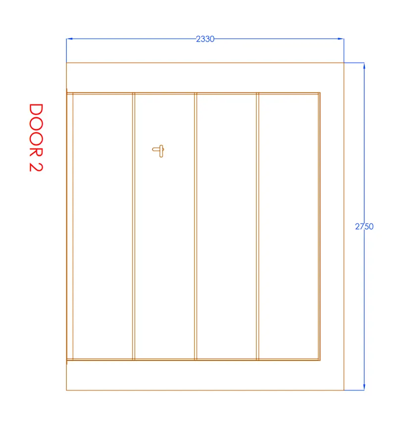
The door types for warehouse is created as per the given dimensions shown in the figure. All dimensions are in 'mm'
Part A: Door 1
Part B: Door 2
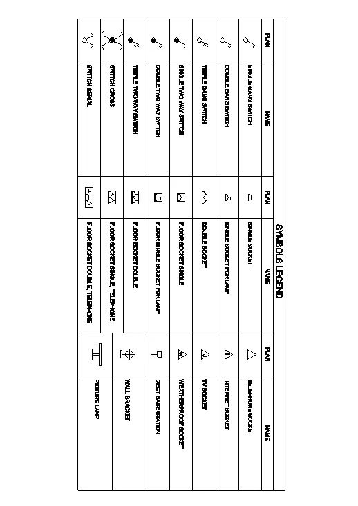
3. Create each symbol as a block with the name given in the legend. After creating the blocks arrange them in the legend as shown in the Figure.
AIM
To create symbol as block with the name given in the legend. After creating the blocks arrange them in the legend as shown in the figure.
INTRODUCTION
In AutoCAD, a block is a collection of objects that are combined into a single named object. To use this function, first create objects and then open 'Block Definition' using command 'B/BLOCK'.
PROCEDURE
Open the AutoCAD Application and create a new AutoCAD file with imperial settings. Set the length type in 'Decimal' and precision (0.00), insertion scale to 'Millimeters' in the Drawing Units and press OK. Set limits and zoom all.
Layers are created, the different layers used in this project is shown below
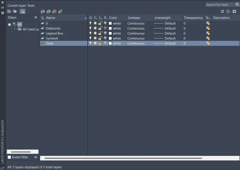
1. Create symbols as blocks
- Type 'LA' in the command line and enter to get layer properties
- Create a new layer "Symbols"
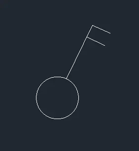
a) Single gang switch
- Type 'C' in the command line and enter to get circle
- Draw a circle of radius 160mm
- Type 'L' in the command line and enter to get line
- Draw lines according to the given figure

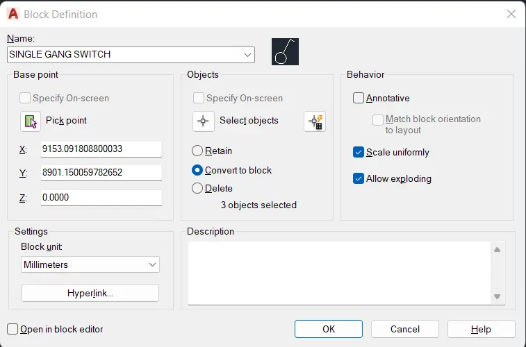
- Type 'B' in the command line and enter to get block definition
- Name: 'SINGLE GANG SWITCH'
- Base point: Pick point from the screen according to the design
- Objects: Select ojects from the screen, click 'Convert to block'
- Behavior: Tick 'Scale uniformly' and 'Allow exploding'
- Settings: Block unit as 'Millimeters'
- Press OK
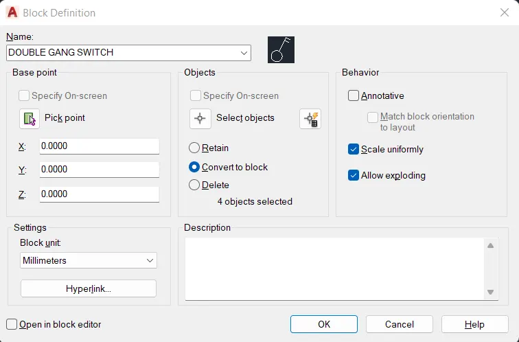
b) Double gang switch
- Type 'C' in the command line and enter to get circle
- Draw a circle of radius 160mm
- Type 'L' in the command line and enter to get line
- Draw lines according to the given figure
- Type 'B' in the command line and enter to get block definition
- Name: 'DOUBLE GANG SWITCH'
- Base point: Pick point from the screen according to the design
- Objects: Select ojects from the screen, click 'Convert to block'
- Behavior: Tick 'Scale uniformly' and 'Allow exploding'
- Settings: Block unit as 'Millimeters'
- Press OK
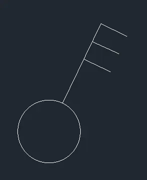
c) Triple gang switch
- Type 'C' in the command line and enter to get circle
- Draw a circle of radius 160mm
- Type 'L' in the command line and enter to get line
- Draw lines according to the given figure
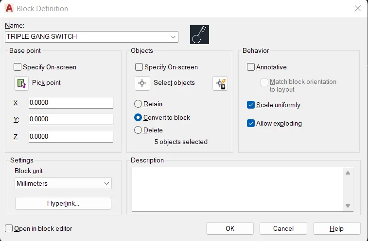
- Type 'B' in the command line and enter to get block definition
- Name: 'TRIPLE GANG SWITCH'
- Base point: Pick point from the screen according to the design
- Objects: Select ojects from the screen, click 'Convert to block'
- Behavior: Tick 'Scale uniformly' and 'Allow exploding'
- Settings: Block unit as 'Millimeters'
- Press OK
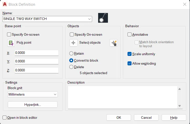
d) Single two way switch
- Type 'C' in the command line and enter to get circle
- Draw a circle of radius 160mm
- Draw a circle of radius 120mm
- Type 'L' in the command line and enter to get line
- Draw lines according to the given figure
- Type 'H' in the command line and enter to hatch properties
- Pick internal point: Pick the internal circle (Pattern: SOLID)

- Type 'B' in the command line and enter to get block definition
- Name: 'SINGLE TWO WAY SWITCH'
- Base point: Pick point from the screen according to the design
- Objects: Select ojects from the screen, click 'Convert to block'
- Behavior: Tick 'Scale uniformly' and 'Allow exploding'
- Settings: Block unit as 'Millimeters'
- Press OK
e) Double two way switch
- Type 'C' in the command line and enter to get circle
- Draw a circle of radius 160mm
- Draw a circle of radius 120mm
- Type 'L' in the command line and enter to get line
- Draw lines according to the given figure
- Type 'H' in the command line and enter to hatch properties
- Pick internal point: Pick the internal circle (Pattern: SOLID)

- Type 'B' in the command line and enter to get block definition
- Name: 'DOUBLE TWO WAY SWITCH'
- Base point: Pick point from the screen according to the design
- Objects: Select ojects from the screen, click 'Convert to block'
- Behavior: Tick 'Scale uniformly' and 'Allow exploding'
- Settings: Block unit as 'Millimeters'
- Press OK
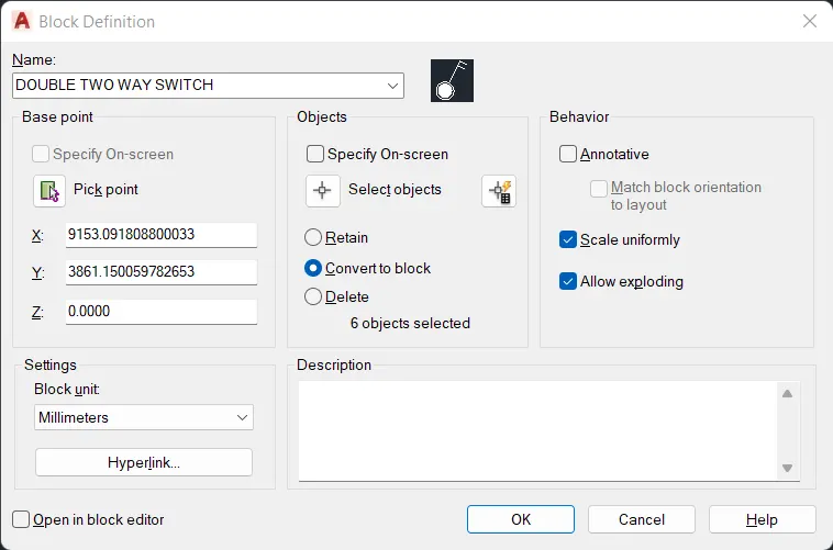
f) Triple two way switch
- Type 'C' in the command line and enter to get circle
- Draw a circle of radius 160mm
- Draw a circle of radius 120mm
- Type 'L' in the command line and enter to get line
- Draw lines according to the given figure
- Type 'H' in the command line and enter to hatch properties
- Pick internal point: Pick the internal circle (Pattern: SOLID)

- Type 'B' in the command line and enter to get block definition
- Name: 'TRIPLE TWO WAY SWITCH'
- Base point: Pick point from the screen according to the design
- Objects: Select ojects from the screen, click 'Convert to block'
- Behavior: Tick 'Scale uniformly' and 'Allow exploding'
- Settings: Block unit as 'Millimeters'
- Press OK
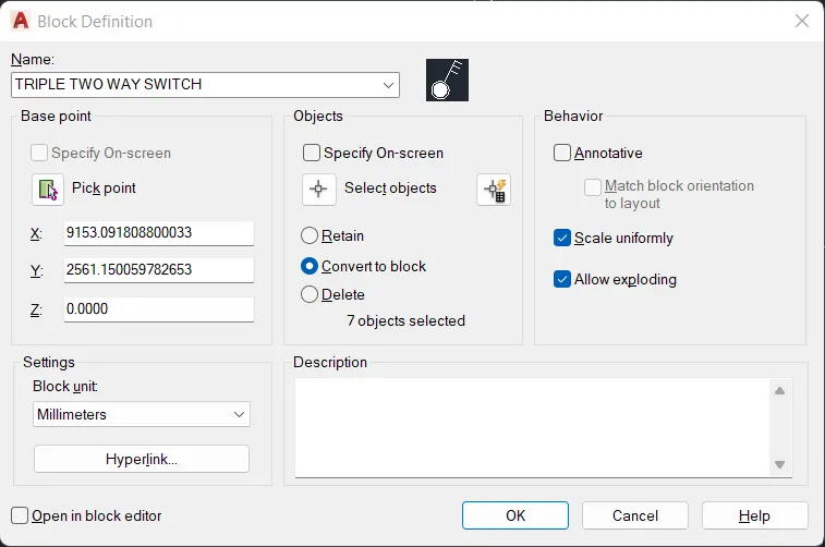
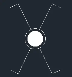
g) Switch cross
- Type 'C' in the command line and enter to get circle
- Draw a circle of radius 160mm
- Draw a circle of radius 120mm
- Type 'L' in the command line and enter to get line
- Draw lines according to the given figure
- Type 'H' in the command line and enter to hatch properties
- Pick internal point: Pick the internal circle (Pattern: SOLID)
- Type 'B' in the command line and enter to get block definition
- Name: 'SWITCH CROSS'
- Base point: Pick point from the screen according to the design
- Objects: Select ojects from the screen, click 'Convert to block'
- Behavior: Tick 'Scale uniformly' and 'Allow exploding'
- Settings: Block unit as 'Millimeters'
- Press OK
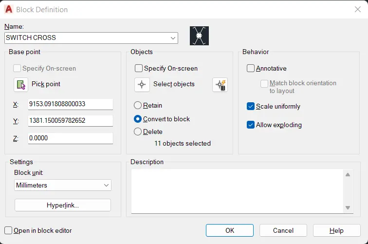
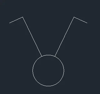
h) Switch serial
- Type 'C' in the command line and enter to get circle
- Draw a circle of radius 160mm
- Type 'L' in the command line and enter to get line
- Draw lines according to the given figure
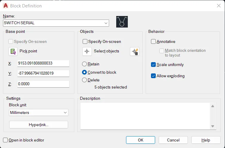
- Type 'B' in the command line and enter to get block definition
- Name: 'SWITCH SERIAL'
- Base point: Pick point from the screen according to the design
- Objects: Select ojects from the screen, click 'Convert to block'
- Behavior: Tick 'Scale uniformly' and 'Allow exploding'
- Settings: Block unit as 'Millimeters'
- Press OK
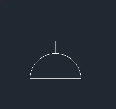
i) Single sockect
- Type 'C' in the command line and enter to get circle
- Draw a circle of radius 200mm
- Type 'L' in the command line and enter to get line
- Draw lines according to the given figure
- Type 'TR' in the command line and enter to get trim tool
- Trim all unnecessary lines
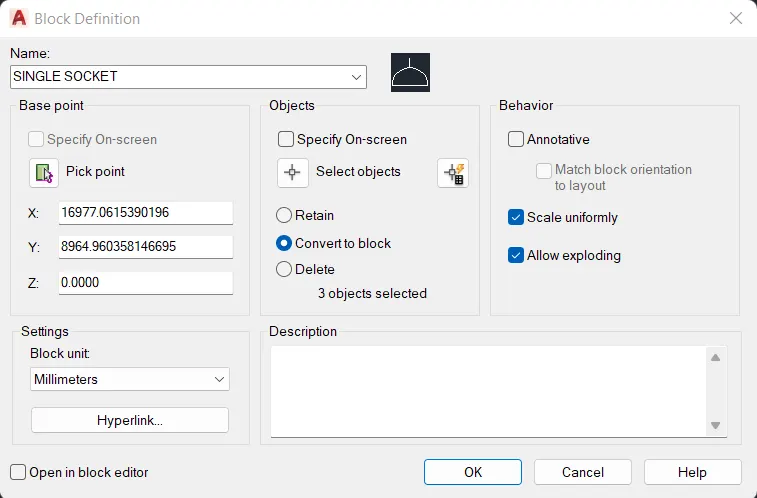
- Type 'B' in the command line and enter to get block definition
- Name: 'SINGLE SOCKET'
- Base point: Pick point from the screen according to the design
- Objects: Select ojects from the screen, click 'Convert to block'
- Behavior: Tick 'Scale uniformly' and 'Allow exploding'
- Settings: Block unit as 'Millimeters'
- Press OK
j) Single sockect for lamp
- Type 'C' in the command line and enter to get circle
- Draw a circle of radius 200mm
- Type 'L' in the command line and enter to get line
- Draw lines according to the given figure
- Type 'TR' in the command line and enter to get trim tool
- Trim all unnecessary lines
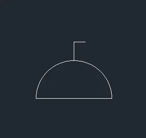
- Type 'B' in the command line and enter to get block definition
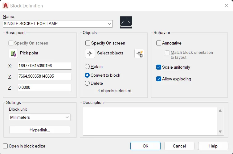
- Name: 'SINGLE SOCKET FOR LAMP'
- Base point: Pick point from the screen according to the design
- Objects: Select ojects from the screen, click 'Convert to block'
- Behavior: Tick 'Scale uniformly' and 'Allow exploding'
- Settings: Block unit as 'Millimeters'
- Press OK
k) Double sockect
- Type 'C' in the command line and enter to get circle
- Draw a circle of radius 200mm
- Type 'L' in the command line and enter to get line
- Draw lines according to the given figure
- Type 'TR' in the command line and enter to get trim tool
- Trim all unnecessary lines
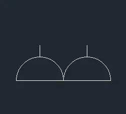
- Type 'B' in the command line and enter to get block definition
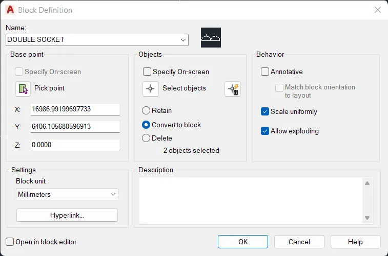
- Name: 'DOUBLE SOCKET'
- Base point: Pick point from the screen according to the design
- Objects: Select ojects from the screen, click 'Convert to block'
- Behavior: Tick 'Scale uniformly' and 'Allow exploding'
- Settings: Block unit as 'Millimeters'
- Press OK
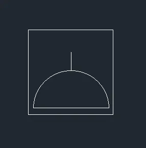
l) Floor sockect single
- Type 'C' in the command line and enter to get circle
- Draw a circle of radius 200mm
- Type 'L' in the command line and enter to get line
- Draw lines according to the given figure
- Type 'TR' in the command line and enter to get trim tool
- Trim all unnecessary lines
- Type 'REC' in the command line and enter to get rectangle
- Draw a rectangle of 450mmx450mm outside the arc
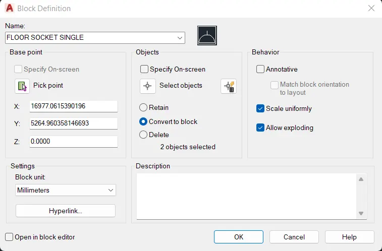
- Type 'B' in the command line and enter to get block definition
- Name: 'FLOOR SOCKET SINGLE'
- Base point: Pick point from the screen according to the design
- Objects: Select ojects from the screen, click 'Convert to block'
- Behavior: Tick 'Scale uniformly' and 'Allow exploding'
- Settings: Block unit as 'Millimeters'
- Press OK
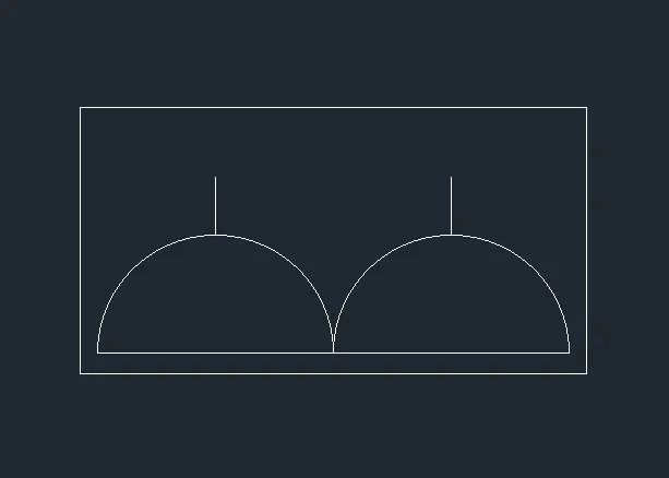
m) Floor sockect double
- Type 'C' in the command line and enter to get circle
- Draw 2 circle of radius 200mm
- Type 'L' in the command line and enter to get line
- Draw lines according to the given figure
- Type 'TR' in the command line and enter to get trim tool
- Trim all unnecessary lines
- Type 'REC' in the command line and enter to get rectangle
- Draw a rectangle of 850mmx450mm outside the arcs
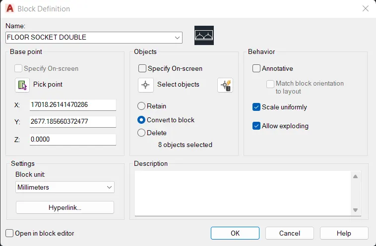
- Type 'B' in the command line and enter to get block definition
- Name: 'FLOOR SOCKET DOUBLE'
- Base point: Pick point from the screen according to the design
- Objects: Select ojects from the screen, click 'Convert to block'
- Behavior: Tick 'Scale uniformly' and 'Allow exploding'
- Settings: Block unit as 'Millimeters'
- Press OK
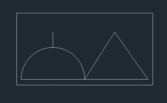
n) Floor sockect single, telephone
- Type 'C' in the command line and enter to get circle
- Draw a circle of radius 200mm
- Type 'L' in the command line and enter to get line
- Draw lines according to the given figure
- Type 'TR' in the command line and enter to get trim tool
- Trim all unnecessary lines
- Type 'POL' in the command line and enter to get polygon
- Draw a polygon of 3 sides
- Type 'REC' in the command line and enter to get rectangle
- Draw a rectangle of 850mmx450mm outside the arcs
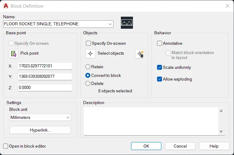
- Type 'B' in the command line and enter to get block definition
- Name: 'FLOOR SOCKET SINGLE, TELEPHONE'
- Base point: Pick point from the screen according to the design
- Objects: Select ojects from the screen, click 'Convert to block'
- Behavior: Tick 'Scale uniformly' and 'Allow exploding'
- Settings: Block unit as 'Millimeters'
- Press OK
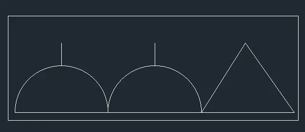
o) Floor sockect double, telephone
- Type 'C' in the command line and enter to get circle
- Draw 2 circle of radius 200mm
- Type 'L' in the command line and enter to get line
- Draw lines according to the given figure
- Type 'TR' in the command line and enter to get trim tool
- Trim all unnecessary lines
- Type 'POL' in the command line and enter to get polygon
- Draw a polygon of 3 sides
- Type 'REC' in the command line and enter to get rectangle
- Draw a rectangle of 1120mmx405mm outside the arcs
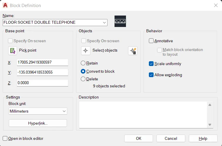
- Type 'B' in the command line and enter to get block definition
- Name: 'FLOOR SOCKET DOUBLE, TELEPHONE'
- Base point: Pick point from the screen according to the design
- Objects: Select ojects from the screen, click 'Convert to block'
- Behavior: Tick 'Scale uniformly' and 'Allow exploding'
- Settings: Block unit as 'Millimeters'
- Press OK
p) Telephone sockect
- Type 'POL' in the command line and enter to get polygon
- Draw a polygon of 3 sides
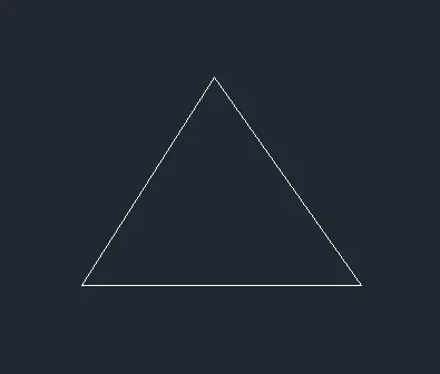
- Type 'B' in the command line and enter to get block definition
- Name: 'TELEPHONE SOCKET'
- Base point: Pick point from the screen according to the design
- Objects: Select ojects from the screen, click 'Convert to block'
- Behavior: Tick 'Scale uniformly' and 'Allow exploding'
- Settings: Block unit as 'Millimeters'
- Press OK
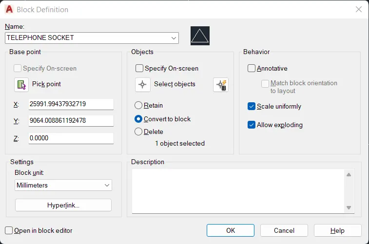
q) Internet sockect
- Type 'POL' in the command line and enter to get polygon
- Draw a polygon of 3 sides
- Type 'MTEXT' in the command line and enter to get multi line text
- Type text wherever required

- Type 'B' in the command line and enter to get block definition
- Name: 'INTERNET SOCKET'
- Base point: Pick point from the screen according to the design
- Objects: Select ojects from the screen, click 'Convert to block'
- Behavior: Tick 'Scale uniformly' and 'Allow exploding'
- Settings: Block unit as 'Millimeters'
- Press OK
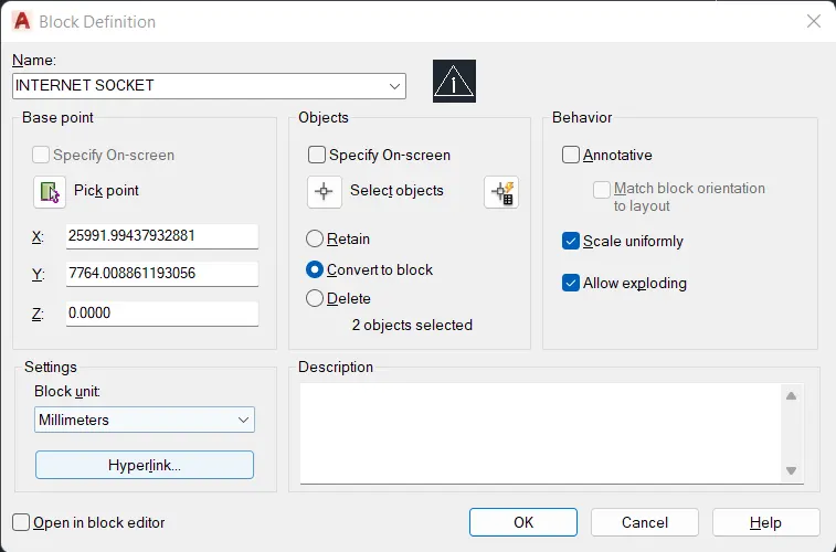
r) TV sockect
- Type 'POL' in the command line and enter to get polygon
- Draw a polygon of 3 sides
- Type 'MTEXT' in the command line and enter to get multi line text
- Type text wherever required

- Type 'B' in the command line and enter to get block definition
- Name: 'TV SOCKET'
- Base point: Pick point from the screen according to the design
- Objects: Select ojects from the screen, click 'Convert to block'
- Behavior: Tick 'Scale uniformly' and 'Allow exploding'
- Settings: Block unit as 'Millimeters'
- Press OK
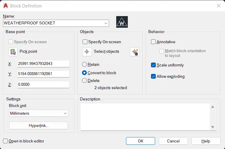
s) Weatherproof sockect
- Type 'POL' in the command line and enter to get polygon
- Draw a polygon of 3 sides
- Type 'MTEXT' in the command line and enter to get multi line text
- Type text wherever required

- Type 'B' in the command line and enter to get block definition
- Name: 'WEATHERPROOF SOCKET'
- Base point: Pick point from the screen according to the design
- Objects: Select ojects from the screen, click 'Convert to block'
- Behavior: Tick 'Scale uniformly' and 'Allow exploding'
- Settings: Block unit as 'Millimeters'
- Press OK
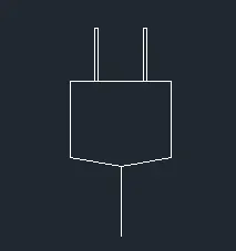
t) Dect base station
- Type 'POL' in the command line and enter to get polygon
- Draw a polygon of 5 sides
- Type 'L' in the command line and enter to get line
- Draw lines according to the given figure
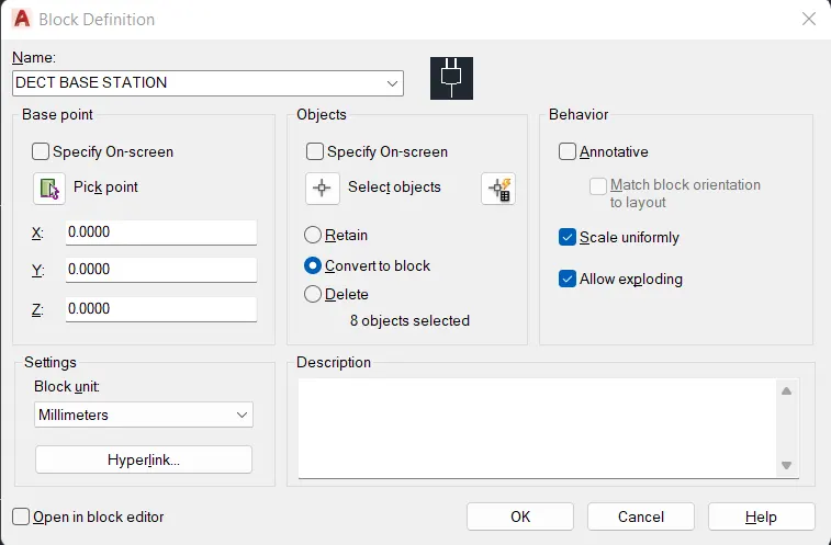
- Type 'B' in the command line and enter to get block definition
- Name: 'DECT BASE STATION'
- Base point: Pick point from the screen according to the design
- Objects: Select ojects from the screen, click 'Convert to block'
- Behavior: Tick 'Scale uniformly' and 'Allow exploding'
- Settings: Block unit as 'Millimeters'
- Press OK
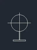
u) Wall bracket
- Type 'C' in the command line and enter to get circle
- Draw a circle of radius 250mm
- Type 'L' in the command line and enter to get line
- Draw lines according to the given figure
- Type 'REC' in the command line and enter to get rectangle
- Draw a rectangle of 15mmx254mm
- Draw a rectangle of 370mmx28mm
- Type 'B' in the command line and enter to get block definition
- Name: 'WALL BRACKET'
- Base point: Pick point from the screen according to the design
- Objects: Select ojects from the screen, click 'Convert to block'
- Behavior: Tick 'Scale uniformly' and 'Allow exploding'
- Settings: Block unit as 'Millimeters'
- Press OK
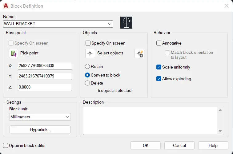
v) Picture lamp
- Type 'REC' in the command line and enter to get rectangle
- Draw a rectangle of 830mmx95mm
- Draw a rectangle of 20mmx375mm
- Draw a rectangle of 550mmx40mm
- Type 'B' in the command line and enter to get block definition
- Name: 'PICTURE LAMP'
- Base point: Pick point from the screen according to the design
- Objects: Select ojects from the screen, click 'Convert to block'
- Behavior: Tick 'Scale uniformly' and 'Allow exploding'
- Settings: Block unit as 'Millimeters'
- Press OK
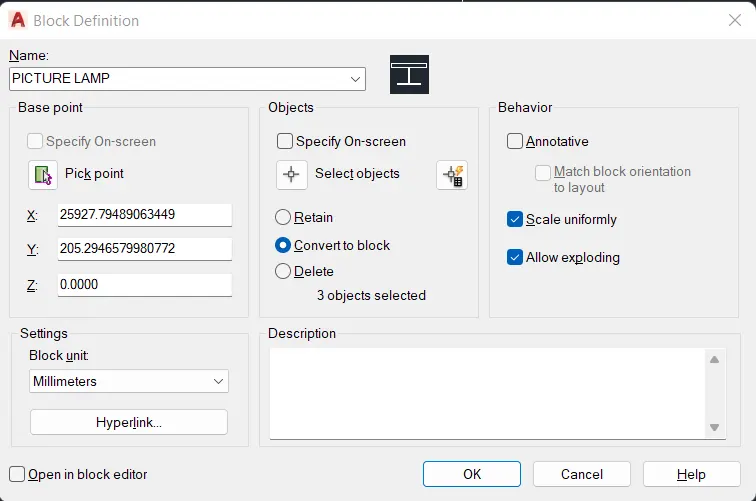
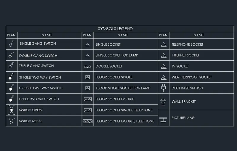
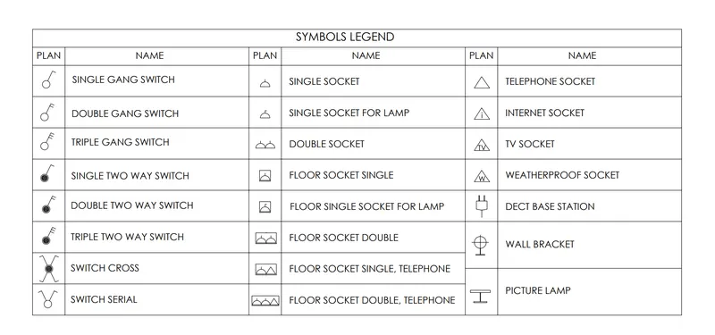
2. Create legend box
- Type 'LA' in the command line and enter to get layer properties
- Create a new layer "Legend Box"
- Type 'REC' in the command line and enter to get rectangle
- Draw legend box using rectangles
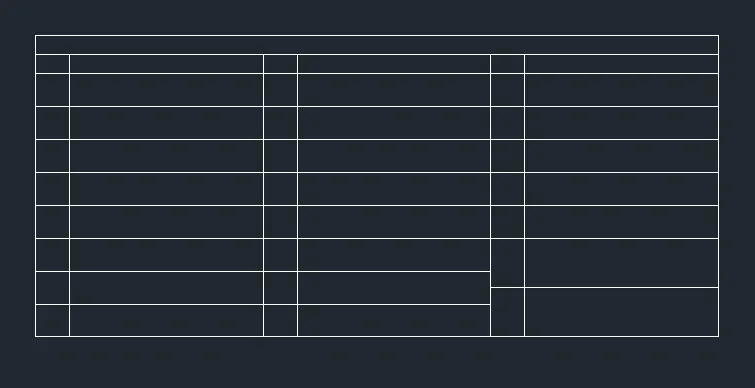
3. Insert symbols into the legend box
- Type 'MO' in the command line and enter to get move tool
- Select each symbol and place it in each box according to the figure
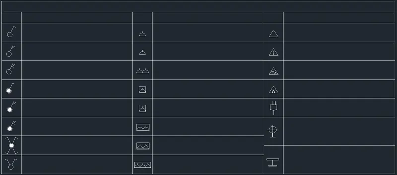
4. Insert texts in appropiate places
- Type 'LA' in the command line and enter to get layer properties
- Create a new layer "Texts"
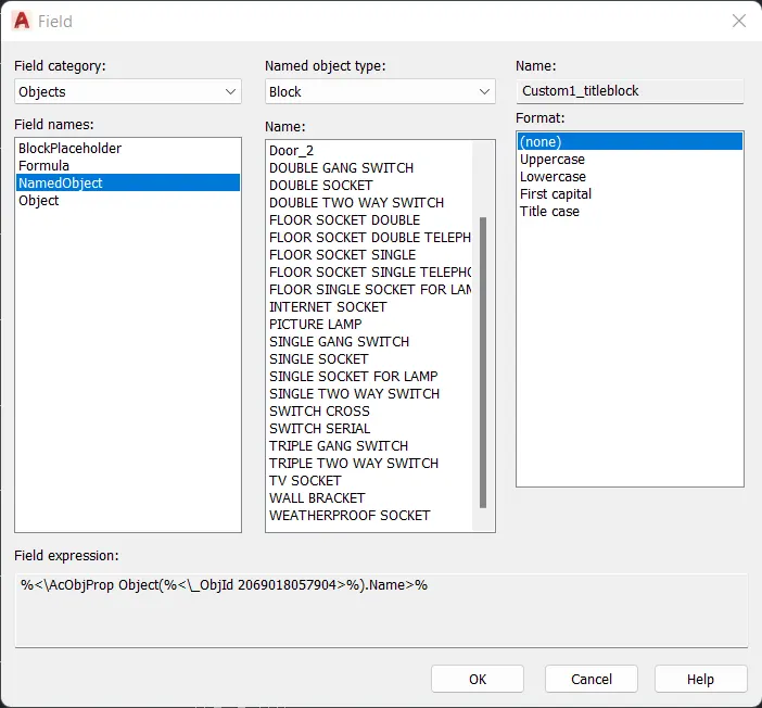
- In the 'Insert' tab, click 'Field' to open field dailogue box
- Select each name and place it in the legend box according to the drawn symbols
- Type 'MTEXT' in the command line and enter to get multi line text
- Type text wherever required in the legend box
RESULT
Each symbols are created as blocks with names and given in the legend. All dimensions are in 'mm'
4. Create the door type for residential building as a block. Save the name of the blocks as type. Use given dimensions or assume dimensions as per industry standards.
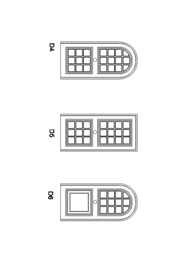
AIM
To create the door type for residential building as a block
INTRODUCTION
In AutoCAD, a block is a collection of objects that are combined into a single named object. To use this function, first create objects and then open 'Block Definition' using command 'B/BLOCK'.
PROCEDURE
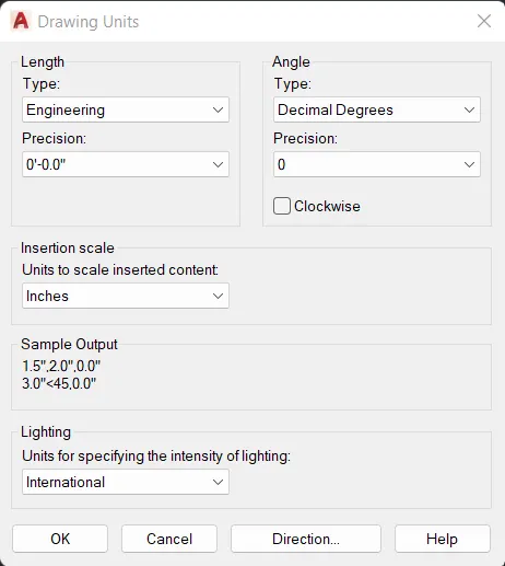
Open the AutoCAD Application and create a new AutoCAD file with imperial settings. Set the length type in 'Engineering' and precision (0'-0.0"), insertion scale to 'Inches' in the Drawing Units and press OK. Set limits and zoom all.
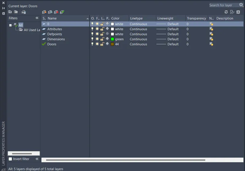
Layers are created, the different layers used in this project is shown below
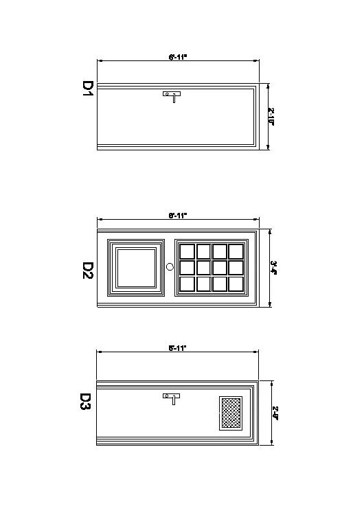
1. Create D1 as block
- Type 'LA' in the command line and enter to get layer properties
- Create a new layer "Doors"
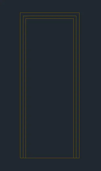
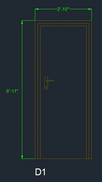
a) Draw D1 outline
- Type 'REC' in the command line and enter to get rectangle
- Draw a rectangle of size 2'10"x6'11"
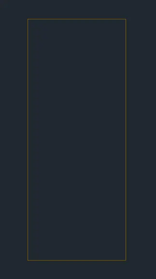
- Select the rectangle and type 'EXPLODE'
- Select the top, right, left line and type 'J'
- Type 'OFF' in the command line and enter to get offset tool
- Offset 1.8" from the polyline inwards
- Offset 1.5" from the new polyline inwards
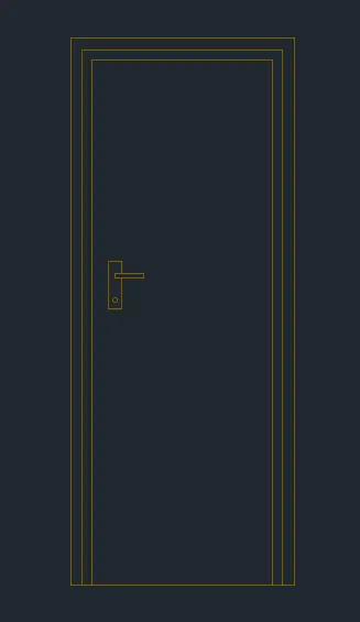
b) Draw door handle
- Type 'REC' in the command line and enter to get rectangle
- Draw a rectangle of size 1.9"x7.3"
- Draw a rectangle of size 4.3"x0.6"
- Type 'C' in the command line and enter to get circle
- Draw a circle of radius 0.4"
- Type 'M' in the command line and enter to get move
- Arrange all the parts to create door handle
- Type 'TR' in the command line and enter to get trim tool
- Trim unnecssary lines
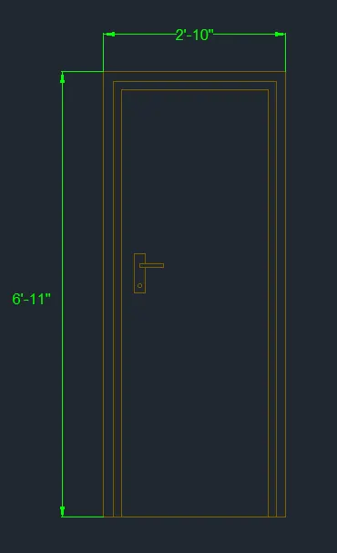
c) Insert dimensions
- Type 'LA' in the command line and enter to get layer properties
- Create a new layer "Dimensions"
- Type 'DIMSTY' in the command line and enter to get dimension style settings
- Dimension Style is created as New, the settings are shown below
- In Symbols and Arrows, Arrow size is given as 2"
- In Text, Text height is given as 2"
- In Fit, Overall scale is given as 1
- Type 'DIM' in the command line and enter to get dimension line
- Mark all necessary dimensions
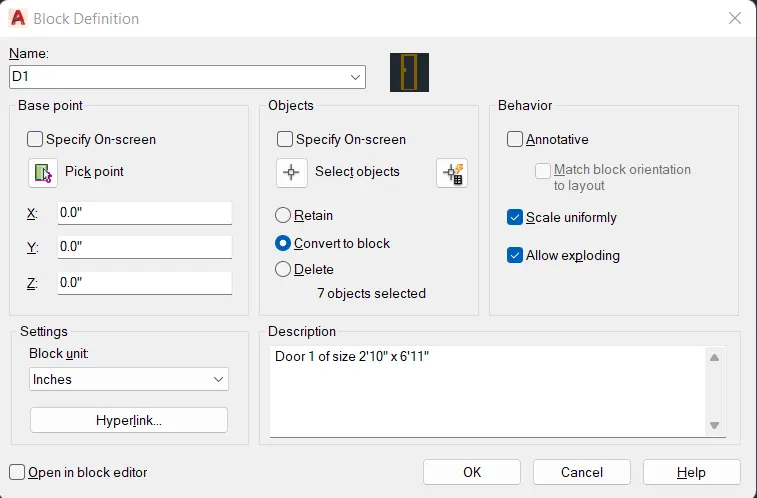
d) Convert to block
- Type 'B' in the command line and enter to get block definition
- Name: 'D1'
- Base point: Pick point from the screen according to the design
- Objects: Select ojects from the screen, click 'Convert to block'
- Behavior: Tick 'Scale uniformly' and 'Allow exploding'
- Settings: Block unit as 'Inches'
- Description: 'Door 1 of size 2'10" x 6'11"'
- Press OK
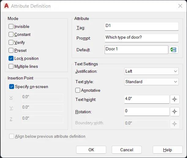
e) Give attribute
- Type 'LA' in the command line and enter to get layer properties
- Create a new layer "Attributes"
- Type 'ATT' in the command line and enter to get attribute definition
- Tag: 'D1'
- Prompt: 'Which type of door?'
- Default: 'Door 1'
- Mode: Tick 'Lock position'
2. Create D2 as block
- Select "Doors" layer
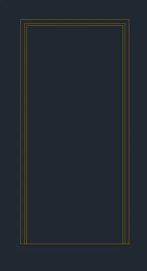
a) Draw D2 outline
- Type 'REC' in the command line and enter to get rectangle
- Draw a rectangle of size 3'4"x6'11"
- Select the rectangle and type 'EXPLODE'
- Select the top, right, left line and type 'J' to join
- Type 'OFF' in the command line and enter to get offset tool
- Offset necessary lines to draw the given design
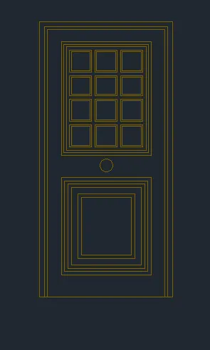
b) Draw door interior
- Type 'REC' in the command line and enter to get rectangle
- Draw rectangles for interior of the door
- Type 'L' in the command line and enter to get line
- Draw lines to complete interior
- Type 'OFF' in the command line and enter to get offset tool
- Offset necessary rectangles and lines as per the design
- Type 'C' in the command line and enter to get circle
- Draw a circle for interior
- Type 'M' in the command line and enter to get move
- Arrange all the parts to create door interiors
- Type 'TR' in the command line and enter to get trim tool
- Trim unnecssary lines
c) Insert dimensions
- Select "Dimensions" layer
- Type 'DIMSTY' in the command line and enter to get dimension style settings
- Dimension Style is created as New, the settings are shown below
- In Symbols and Arrows, Arrow size is given as 2"
- In Text, Text height is given as 2"
- In Fit, Overall scale is given as 1
- Type 'DIM' in the command line and enter to get dimension line
- Mark all necessary dimensions
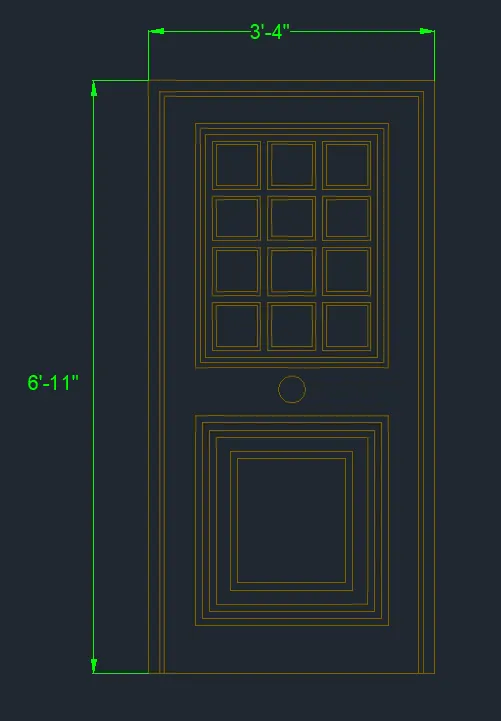
d) Convert to block
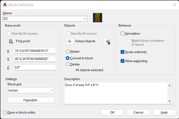
- Type 'B' in the command line and enter to get block definition
- Name: 'D2'
- Base point: Pick point from the screen according to the design
- Objects: Select ojects from the screen, click 'Convert to block'
- Behavior: Tick 'Scale uniformly' and 'Allow exploding'
- Settings: Block unit as 'Inches'
- Description: 'Door 2 of size 3'4" x 6'11"'
- Press OK
e) Give attribute
- Select "Attributes" layer
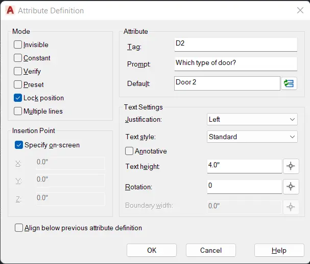
- Type 'ATT' in the command line and enter to get attribute definition
- Tag: 'D2'
- Prompt: 'Which type of door?'
- Default: 'Door 2'
- Mode: Tick 'Lock position'
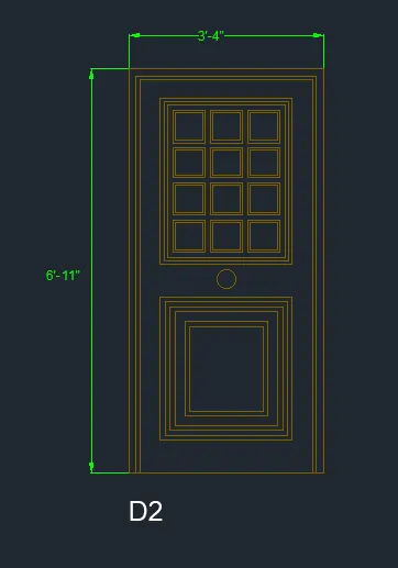
3. Create D3 as block
- Select "Doors" layer
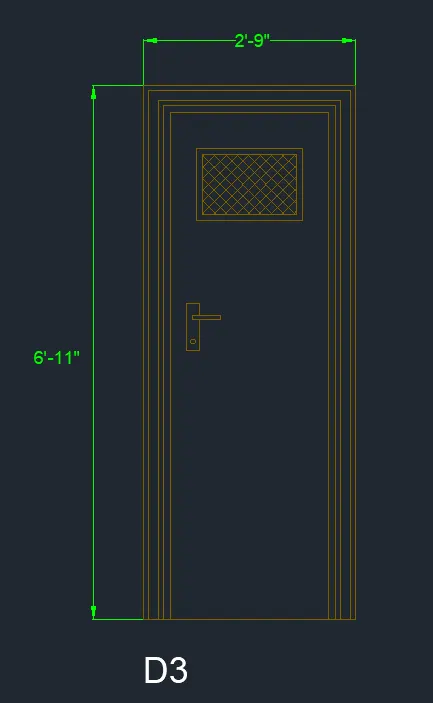
a) Draw D3 outline
- Type 'REC' in the command line and enter to get rectangle
- Draw a rectangle of size 2'9"x6'11"
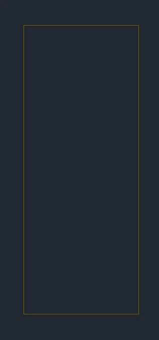
- Select the rectangle and type 'EXPLODE'
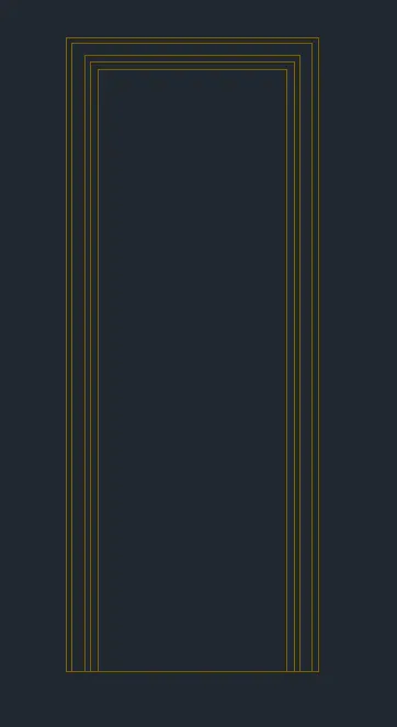
- Select the top, right, left line and type 'J' to join
- Type 'OFF' in the command line and enter to get offset tool
- Offset essential lines to draw the given design
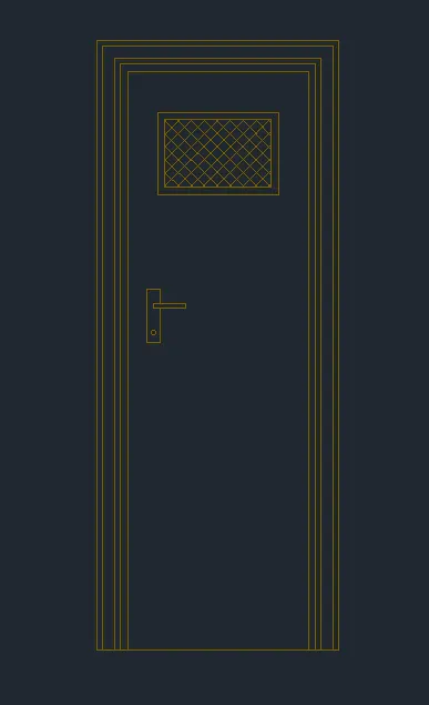
b) Draw door interior
- Type 'REC' in the command line and enter to get rectangle
- Draw rectangles for interior of the door
- Type 'OFF' in the command line and enter to get offset tool
- Offset necessary rectangles and lines as per the design
- Type 'H' in the command line and enter to ge hatch properties
- Pick internal point: Pick point inisde the rectangle (Pattern: ANSI37)
- Type 'C' in the command line and enter to get circle
- Draw a circle for interior
- Type 'M' in the command line and enter to get move
- Arrange all the parts to create door interiors
- Type 'TR' in the command line and enter to get trim tool
- Trim unnecssary lines
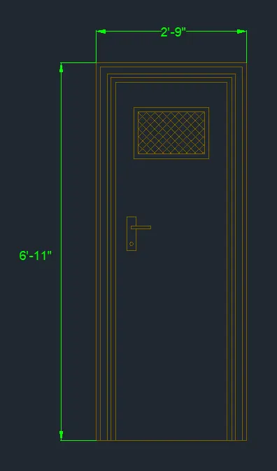
c) Insert dimensions
- Select "Dimensions" layer
- Type 'DIMSTY' in the command line and enter to get dimension style settings
- Dimension Style is created as New, the settings are shown below
- In Symbols and Arrows, Arrow size is given as 2"
- In Text, Text height is given as 2"
- In Fit, Overall scale is given as 1
- Type 'DIM' in the command line and enter to get dimension line
- Mark all necessary dimensions
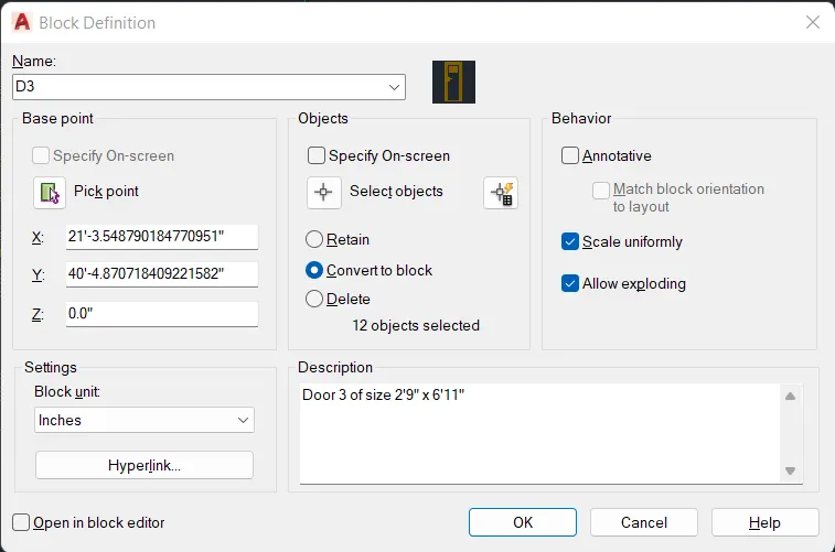
d) Convert to block
- Type 'B' in the command line and enter to get block definition
- Name: 'D3'
- Base point: Pick point from the screen according to the design
- Objects: Select ojects from the screen, click 'Convert to block'
- Behavior: Tick 'Scale uniformly' and 'Allow exploding'
- Settings: Block unit as 'Inches'
- Description: 'Door 3 of size 2'9" x 6'11"'
- Press OK
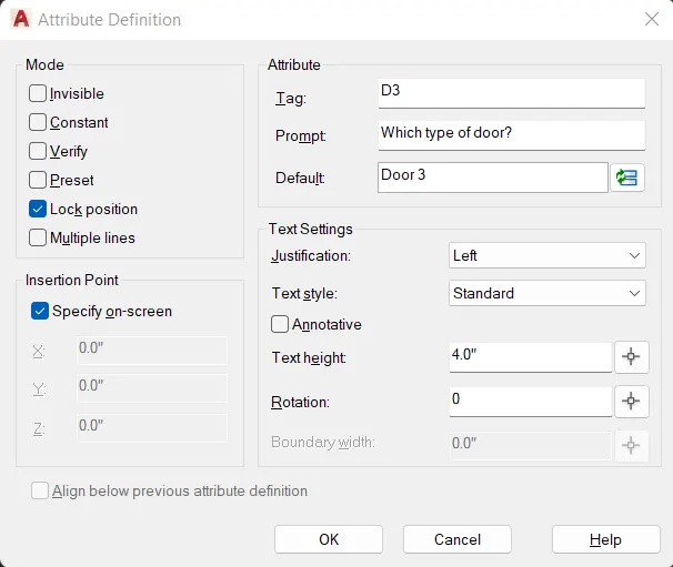
e) Give attribute
- Select "Attributes" layer
- Type 'ATT' in the command line and enter to get attribute definition
- Tag: 'D3'
- Prompt: 'Which type of door?'
- Default: 'Door 3'
- Mode: Tick 'Lock position'
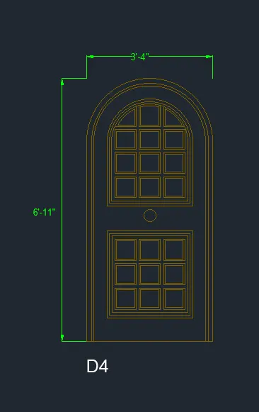
4. Create D4 as block
- Select "Doors" layer
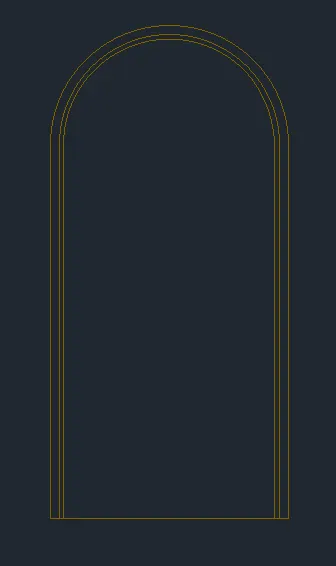
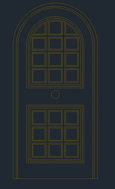
a) Draw D4 outline
- Type 'REC' in the command line and enter to get rectangle
- Draw a rectangle of size 3'4"x6'11"
- Select the rectangle and type 'EXPLODE'
- Select the top, right, left line and type 'J' to join
- Type 'ARC' in the command line and enter to get arc
- Draw arc from one end to another
- Type 'OFF' in the command line and enter to get offset tool
- Offset essential lines and arcs to draw the given design
b) Draw door interior
- Type 'REC' in the command line and enter to get rectangle
- Draw rectangles for interior of the door
- Type 'OFF' in the command line and enter to get offset tool
- Offset necessary rectangles and lines as per the design
- Type 'C' in the command line and enter to get circle
- Draw a circle for interior
- Type 'M' in the command line and enter to get move
- Arrange all the parts to create door interiors
- Type 'TR' in the command line and enter to get trim tool
- Trim unnecssary lines
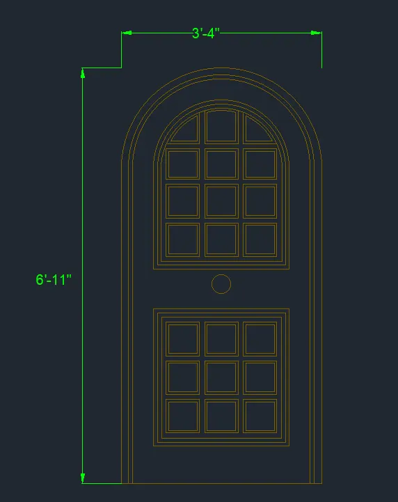
c) Insert dimensions
- Select "Dimensions" layer
- Type 'DIMSTY' in the command line and enter to get dimension style settings
- Dimension Style is created as New, the settings are shown below
- In Symbols and Arrows, Arrow size is given as 2"
- In Text, Text height is given as 2"
- In Fit, Overall scale is given as 1
- Type 'DIM' in the command line and enter to get dimension line
- Mark all necessary dimensions
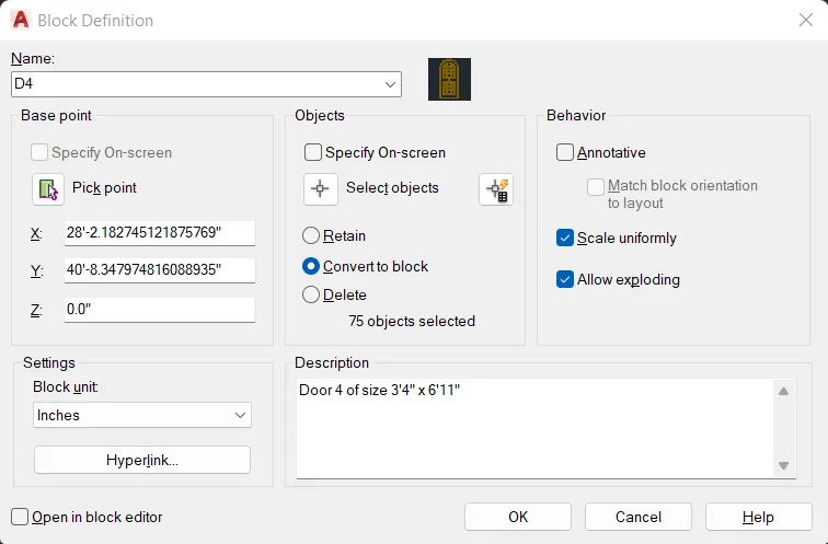
d) Convert to block
- Type 'B' in the command line and enter to get block definition
- Name: 'D4'
- Base point: Pick point from the screen according to the design
- Objects: Select ojects from the screen, click 'Convert to block'
- Behavior: Tick 'Scale uniformly' and 'Allow exploding'
- Settings: Block unit as 'Inches'
- Description: 'Door 4 of size 3'4" x 6'11"'
- Press OK
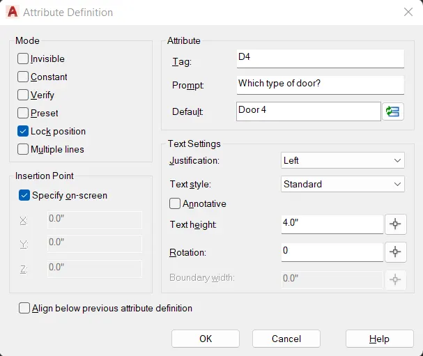
e) Give attribute
- Select "Attributes" layer
- Type 'ATT' in the command line and enter to get attribute definition
- Tag: 'D4'
- Prompt: 'Which type of door?'
- Default: 'Door 4'
- Mode: Tick 'Lock position'
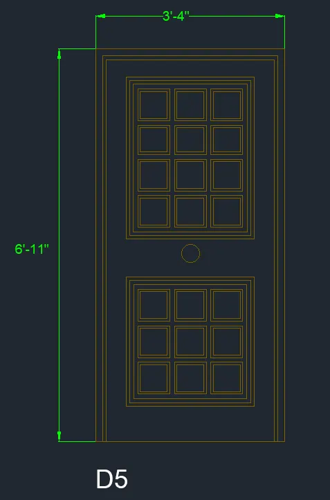
5. Create D5 as block
- Select "Doors" layer
a) Draw D5 outline
- Type 'REC' in the command line and enter to get rectangle
- Draw a rectangle of size 3'4"x6'11"
- Select the rectangle and type 'EXPLODE'
- Select the top, right, left line and type 'J' to join
- Type 'OFF' in the command line and enter to get offset tool
- Offset essential lines to draw the given design
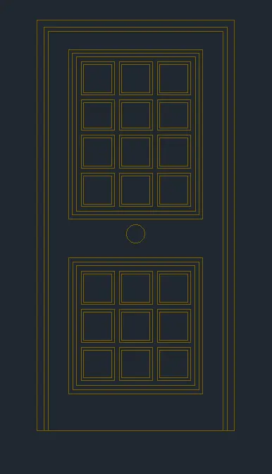
b) Draw door interior
- Type 'REC' in the command line and enter to get rectangle
- Draw rectangles for interior of the door
- Type 'OFF' in the command line and enter to get offset tool
- Offset necessary rectangles and lines as per the design
- Type 'C' in the command line and enter to get circle
- Draw a circle for interior
- Type 'M' in the command line and enter to get move
- Arrange all the parts to create door interiors
- Type 'TR' in the command line and enter to get trim tool
- Trim unnecssary lines
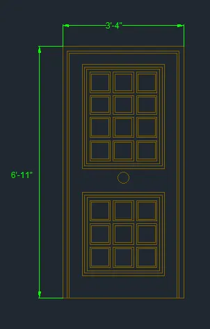
c) Insert dimensions
- Select "Dimensions" layer
- Type 'DIMSTY' in the command line and enter to get dimension style settings
- Dimension Style is created as New, the settings are shown below
- In Symbols and Arrows, Arrow size is given as 2"
- In Text, Text height is given as 2"
- In Fit, Overall scale is given as 1
- Type 'DIM' in the command line and enter to get dimension line
- Mark all necessary dimensions
d) Convert to block
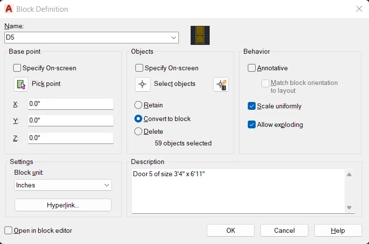
- Type 'B' in the command line and enter to get block definition
- Name: 'D5'
- Base point: Pick point from the screen according to the design
- Objects: Select ojects from the screen, click 'Convert to block'
- Behavior: Tick 'Scale uniformly' and 'Allow exploding'
- Settings: Block unit as 'Inches'
- Description: 'Door 5 of size 3'4" x 6'11"'
- Press OK
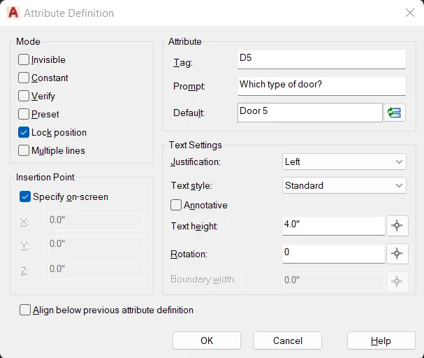
e) Give attribute
- Select "Attributes" layer
- Type 'ATT' in the command line and enter to get attribute definition
- Tag: 'D5'
- Prompt: 'Which type of door?'
- Default: 'Door 5'
- Mode: Tick 'Lock position'
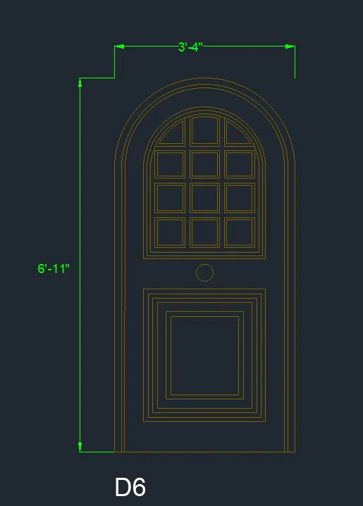
6. Create D6 as block
- Select "Doors" layer
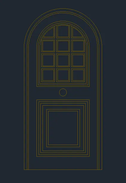
a) Draw D6 outline
- Type 'REC' in the command line and enter to get rectangle
- Draw a rectangle of size 3'4"x6'11"
- Select the rectangle and type 'EXPLODE'
- Select the top, right, left line and type 'J' to join
- Type 'ARC' in the command line and enter to get arc
- Draw arc from one end to another
- Type 'OFF' in the command line and enter to get offset tool
- Offset essential lines and arcs to draw the given design
b) Draw door interior
- Type 'REC' in the command line and enter to get rectangle
- Draw rectangles for interior of the door
- Type 'OFF' in the command line and enter to get offset tool
- Offset necessary rectangles and lines as per the design
- Type 'C' in the command line and enter to get circle
- Draw a circle for interior
- Type 'M' in the command line and enter to get move
- Arrange all the parts to create door interiors
- Type 'TR' in the command line and enter to get trim tool
- Trim unnecssary lines
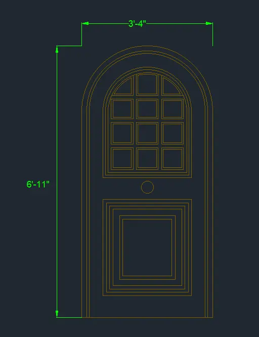
c) Insert dimensions
- Select "Dimensions" layer
- Type 'DIMSTY' in the command line and enter to get dimension style settings
- Dimension Style is created as New, the settings are shown below
- In Symbols and Arrows, Arrow size is given as 2"
- In Text, Text height is given as 2"
- In Fit, Overall scale is given as 1
- Type 'DIM' in the command line and enter to get dimension line
- Mark all necessary dimensions
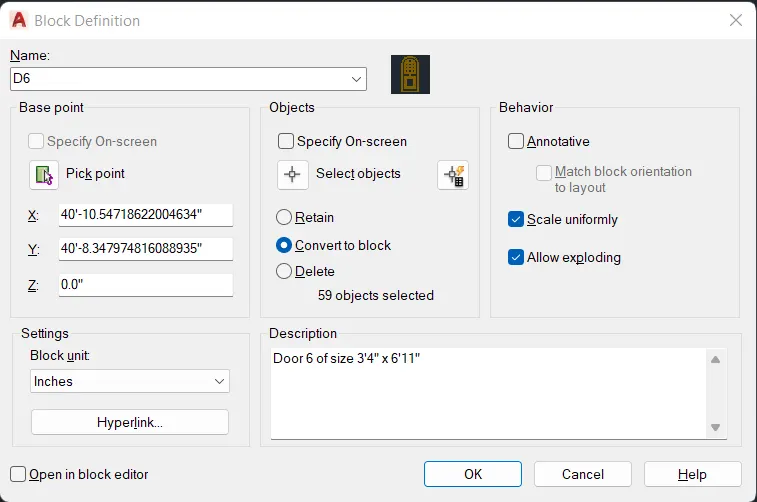
d) Convert to block
- Type 'B' in the command line and enter to get block definition
- Name: 'D6'
- Base point: Pick point from the screen according to the design
- Objects: Select ojects from the screen, click 'Convert to block'
- Behavior: Tick 'Scale uniformly' and 'Allow exploding'
- Settings: Block unit as 'Inches'
- Description: 'Door 6 of size 3'4" x 6'11"'
- Press OK
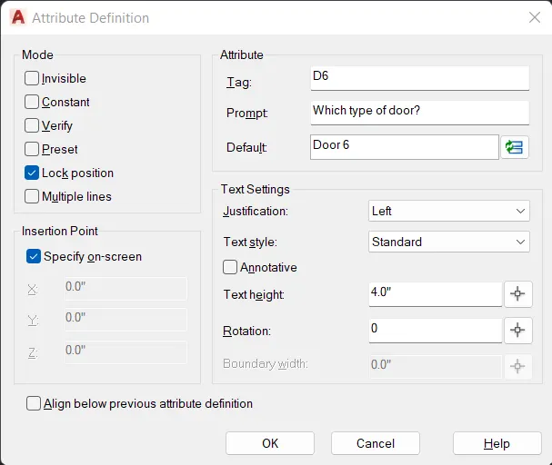
e) Give attribute
- Select "Attributes" layer
- Type 'ATT' in the command line and enter to get attribute definition
- Tag: 'D6'
- Prompt: 'Which type of door?'
- Default: 'Door 6'
- Mode: Tick 'Lock position'
RESULT
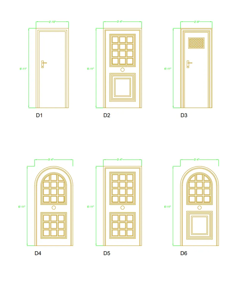
The door types for residential building is created as blocks. All dimensions are in 'feet and inches'.
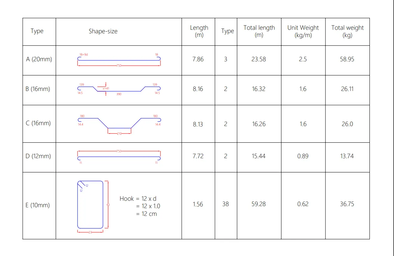
5. Create each shape as a block as shown in the Figure. Save the block and insert them on the table as shown in the Figure.
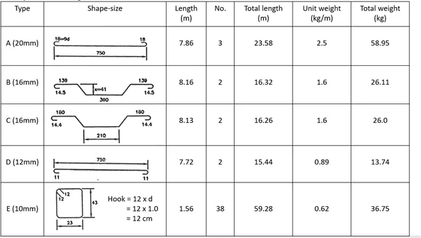
AIM
To create shapes as a block as shown in figure, save the block and insert them on the table as shown in figure
INTRODUCTION
In AutoCAD, a block is a collection of objects that are combined into a single named object. To use this function, first create objects and then open 'Block Definition' using command 'B/BLOCK'.
PROCEDURE
Open the AutoCAD Application and create a new AutoCAD file with imperial settings. Set the length type in 'Decimal' and precision (0.00), insertion scale to 'Millimeters' in the Drawing Units and press OK. Set limits and zoom all.
Layers are created, the different layers used in this project is shown below
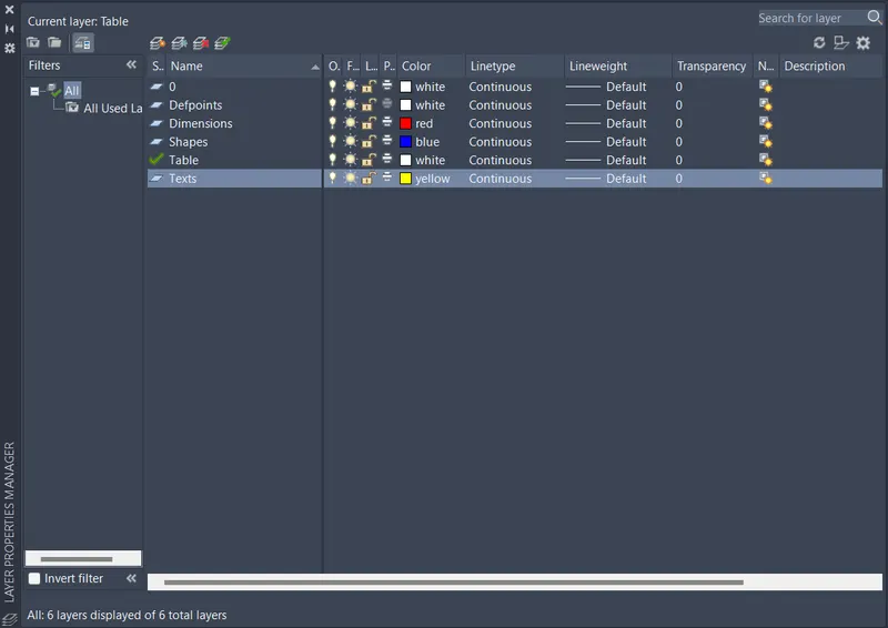
1. Create shapes and save as blocks
- Type 'LA' in the command line and enter to get layer properties
- Create a new layer "Shapes"
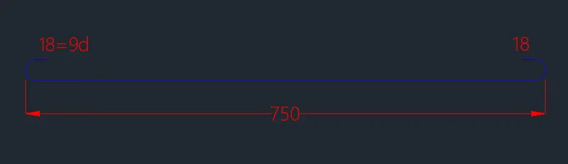
a) Draw shape A
- Type 'L' in the command line and enter to get line
- Draw a horizontal line of 750mm
- Type 'OFF' in the command line and enter to get offset tool
- Offset 30mm from the line drawn
- Type 'F' in the command line and enter to get fillet tool
- Fillet these two lines with diameter 9mm
- Type 'TR' in the command line and enter to get trim tool
- Trim the center part with both ends having 18mm inward extension
- Type 'LA' in the command line and enter to get layer properties
- Create a new layer "Dimensions"
- Type 'DIMSTY' in the command line and enter to get dimension style settings
- Dimension Style is created as New, the settings are shown below
- In Lines, Fixed length extension lines is given as 100mm.
- In Symbols and Arrows, Arrow size is given as 20mm.
- In Text, Text height is given as 20mm
- In Fit, Overall scale is given as 1
- Type 'DIM' in the command line and enter to get dimension line
- Mark all necessary dimensions
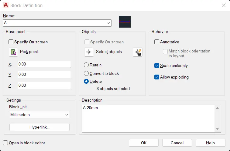
- Type 'B' in the command line and enter to get block definition
- Name: 'A'
- Base point: Pick point from the screen according to the design
- Objects: Select ojects from the screen, click 'Delete'
- Behavior: Tick 'Scale uniformly' and 'Allow exploding'
- Settings: Block unit as 'Millimeters'
- Description: 'A-20mm'
- Press OK
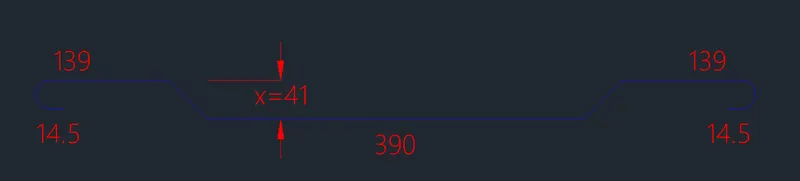
b) Draw shape B
- Type 'L' in the command line and enter to get line
- Draw a horizontal line of 750mm
- Draw two vertical line on both sides
- Draw a line vertical from the midpoint of horizontal line
- Type 'OFF' in the command line and enter to get offset tool
- Offset 41mm from the line drawn
- Offset 139mm from left and right side inwards
- Offset 195mm from vertical midpoint line on both sides
- Type 'F' in the command line and enter to get fillet tool
- Fillet these two lines with diameter 9mm
- Type 'TR' in the command line and enter to get trim tool
- Trim the center part with both ends having 18mm inward extension
- Select "Dimensions" layer
- Type 'DIMSTY' in the command line and enter to get dimension style settings
- Dimension Style is created as New, the settings are shown below
- In Lines, Fixed length extension lines is given as 100mm.
- In Symbols and Arrows, Arrow size is given as 20mm.
- In Text, Text height is given as 20mm
- In Fit, Overall scale is given as 1
- Type 'DIM' in the command line and enter to get dimension line
- Mark all necessary dimensions
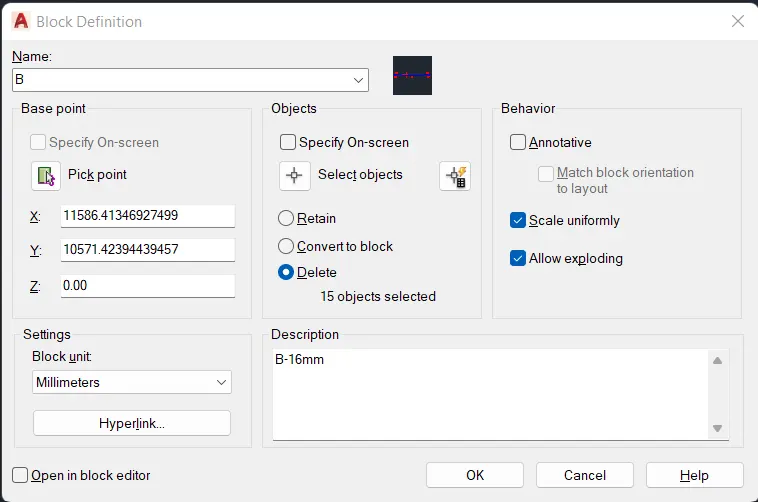
- Type 'B' in the command line and enter to get block definition
- Name: 'B'
- Base point: Pick point from the screen according to the design
- Objects: Select ojects from the screen, click 'Delete'
- Behavior: Tick 'Scale uniformly' and 'Allow exploding'
- Settings: Block unit as 'Millimeters'
- Description: 'B-16mm'
- Press OK
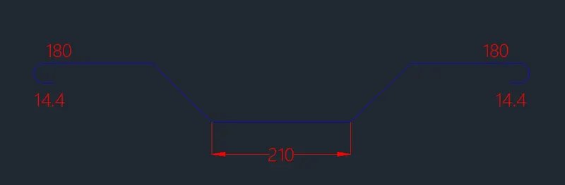
c) Draw shape C
- Type 'L' in the command line and enter to get line
- Draw a horizontal line of 750mm
- Draw two vertical line on both sides
- Draw a line vertical from the midpoint of horizontal line
- Type 'OFF' in the command line and enter to get offset tool
- Offset 180mm from left and right side inwards
- Offset 105mm from vertical midpoint line on both sides
- Type 'L' in the command line and enter to get line
- Draw a line at 45 degree connecting two vertical lines at both sides
- Type 'F' in the command line and enter to get fillet tool
- Fillet these two lines with diameter 9mm
- Type 'TR' in the command line and enter to get trim tool
- Trim the center part with both ends having 18mm inward extension
- Select "Dimensions" layer
- Type 'DIMSTY' in the command line and enter to get dimension style settings
- Dimension Style is created as New, the settings are shown below
- In Lines, Fixed length extension lines is given as 100mm.
- In Symbols and Arrows, Arrow size is given as 20mm.
- In Text, Text height is given as 20mm
- In Fit, Overall scale is given as 1
- Type 'DIM' in the command line and enter to get dimension line
- Mark all necessary dimensions
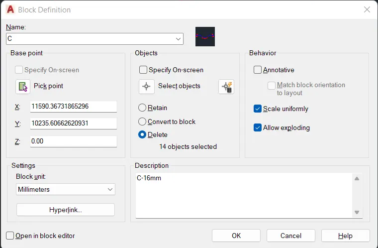
- Type 'C' in the command line and enter to get block definition
- Name: 'C'
- Base point: Pick point from the screen according to the design
- Objects: Select ojects from the screen, click 'Delete'
- Behavior: Tick 'Scale uniformly' and 'Allow exploding'
- Settings: Block unit as 'Millimeters'
- Description: 'C-16mm'
- Press OK
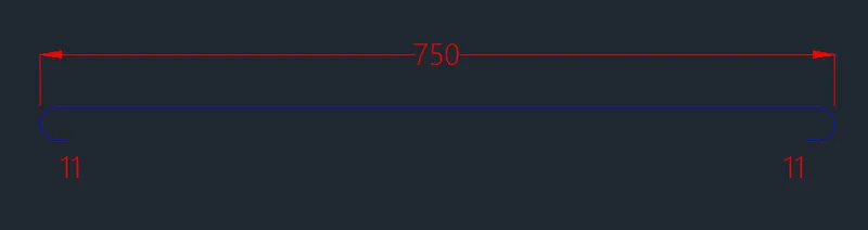
d) Draw shape D
- Type 'L' in the command line and enter to get line
- Draw a horizontal line of 750mm
- Type 'OFF' in the command line and enter to get offset tool
- Offset 30mm from the line drawn
- Type 'F' in the command line and enter to get fillet tool
- Fillet these two lines with diameter 9mm
- Type 'TR' in the command line and enter to get trim tool
- Trim the center part with both ends having 11mm inward extension
- Select "Dimensions" layer
- Type 'DIMSTY' in the command line and enter to get dimension style settings
- Dimension Style is created as New, the settings are shown below
- In Lines, Fixed length extension lines is given as 100mm.
- In Symbols and Arrows, Arrow size is given as 20mm.
- In Text, Text height is given as 20mm
- In Fit, Overall scale is given as 1
- Type 'DIM' in the command line and enter to get dimension line
- Mark all necessary dimensions
- Type 'B' in the command line and enter to get block definition
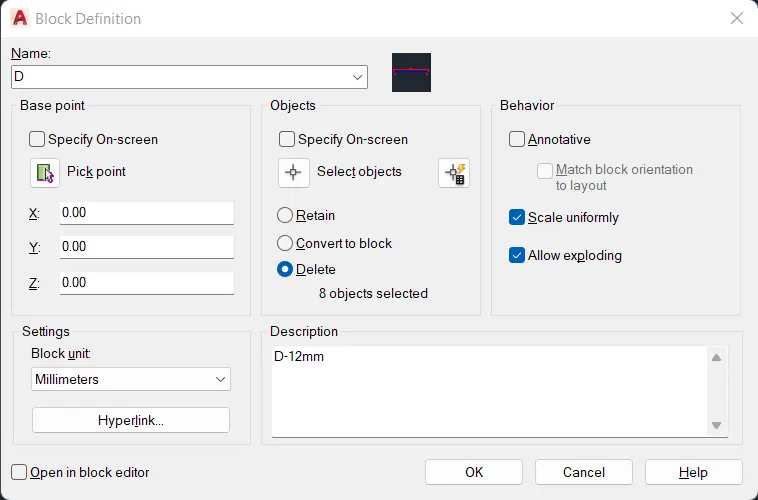
- Name: 'D'
- Base point: Pick point from the screen according to the design
- Objects: Select ojects from the screen, click 'Delete'
- Behavior: Tick 'Scale uniformly' and 'Allow exploding'
- Settings: Block unit as 'Millimeters'
- Description: 'D-12mm'
- Press OK
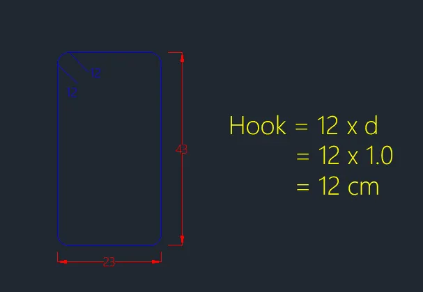
e) Draw shape E
- Type 'REC' in the command line and enter to get rectangle
- Draw a rectangle of size 23mmx43mm
- Select the rectangle and type 'EXPLODE'
- Type 'F' in the command line and enter to get fillet tool
- Fillet all corners of the rectangle with a radius of 9mm
- Type 'L' in the command line and enter to get line
- Draw two 45 degree lines from top-left corner
- Select "Dimensions" layer
- Type 'DIMSTY' in the command line and enter to get dimension style settings
- Dimension Style is created as New, the settings are shown below
- In Lines, Fixed length extension lines is given as 100mm.
- In Symbols and Arrows, Arrow size is given as 20mm.
- In Text, Text height is given as 20mm
- In Fit, Overall scale is given as 1
- Type 'DIM' in the command line and enter to get dimension line
- Mark all necessary dimensions
- Type 'LA' in the command line and enter to get layer properties
- Create a new layer "Texts"
- Type 'MTEXT' in the command line and enter to get multi line text
- Type text wherever required
- Type 'SC' in the command line and enter to get scale tool
- Select all objects and scale factor is taken as 10
- Type 'B' in the command line and enter to get block definition
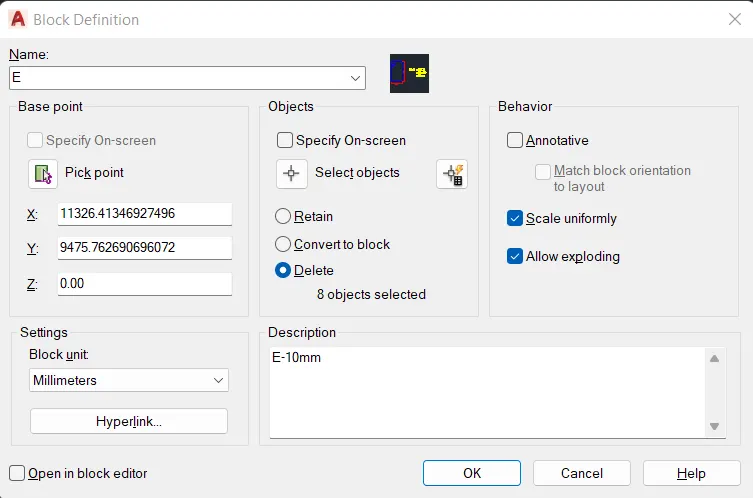
- Name: 'E'
- Base point: Pick point from the screen according to the design
- Objects: Select ojects from the screen, click 'Delete'
- Behavior: Tick 'Scale uniformly' and 'Allow exploding'
- Settings: Block unit as 'Millimeters'
- Description: 'E-10mm'
- Press OK
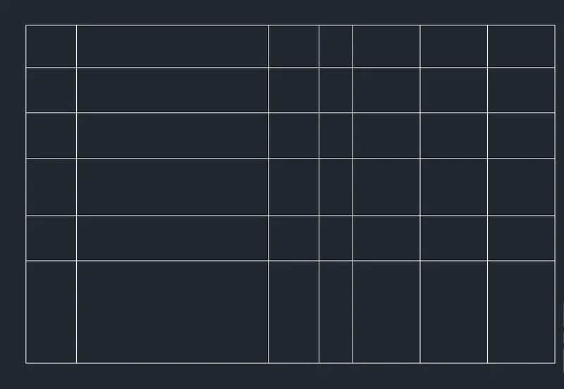
2. Create table
- Type 'L' in the command line and enter to get line
- Draw a vertical and horizontal lines
- Type 'OFF' in the command line and enter to get offset tool
- Offset essential lines to create a table as shown in the figure
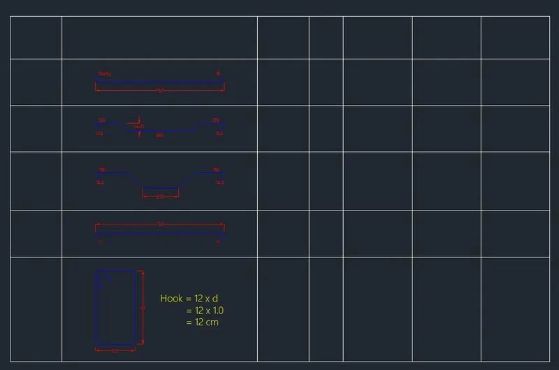
3. Insert blocks inside the table
- Click 'Insert' tab, select each block and place it in the table
4. Insert texts inside the table
- Select "texts" layer
- Type 'MTEXT' in the command line and enter to get multi line text
- Type text wherever required
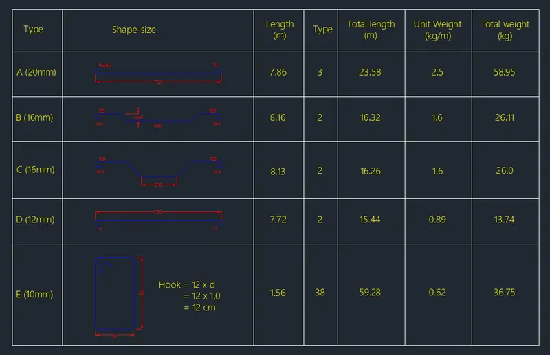
RESULT
The shapes are created as a block as shown in figure, saved the block and inserted them on the table as shown in figure. All dimensions are in 'mm'.