Creating Bar Bending schedule, Different Door types, and Creation of standard drawing templates using AutoCad
1) AIM:
To create the templates title block and need to save it as a block with names:
Custom1_titleblock and
Custom2_titleblock respectively
Introduction:
To create templates title block and need to save it as a block with names:
Custom1_titleblock and
Custom2_titleblock,respectively
Procedure :
Step1:
Creating the custom1_titleblock
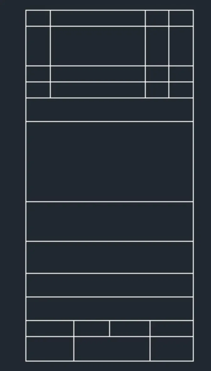
Take a rec command for rectangle and create a rectangle
Next take the explode command ex to break rectangle lines
Next take the offset command and make a table for the placing of the text
Step2:
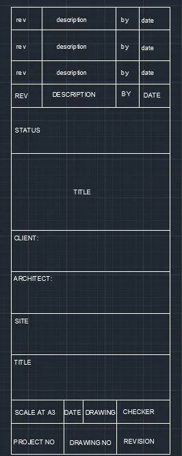
Take the command MTEXT select the base point write the text set the height and rotation of the text
Next place the text and then edit as per requirement of the text
Step3:
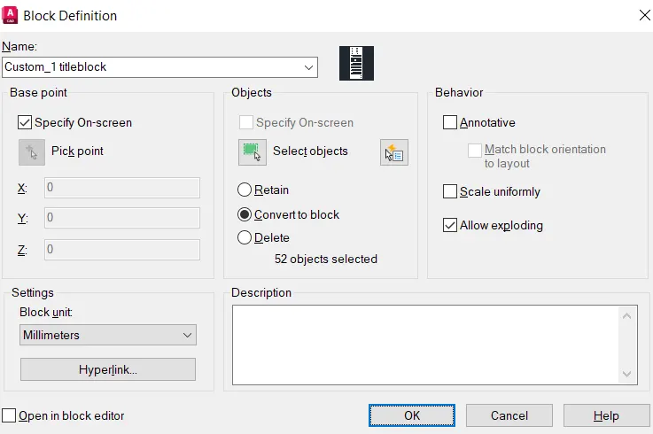
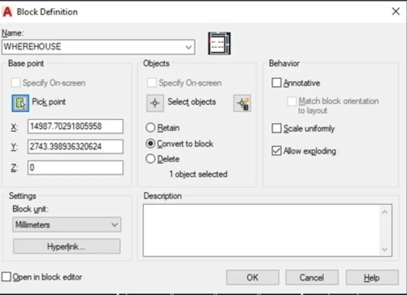
Creating a block
Type b in the command box for the block
Next give the name of the block
Next select the object and pickup point and next click on the creation of the block
II)
Step1:
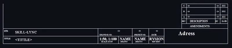
Creating the custom2_titleblock
Take a rec command for rectangle and create a rectangle
Next take the explode command ex to break rectangle lines
Next take the offset command and make a table for the placing of the text

Step2:
Take the command MTEXT select the base point write the text set the height and rotation of the text
Next place the text and then edit as per requirement of the text
Step3:
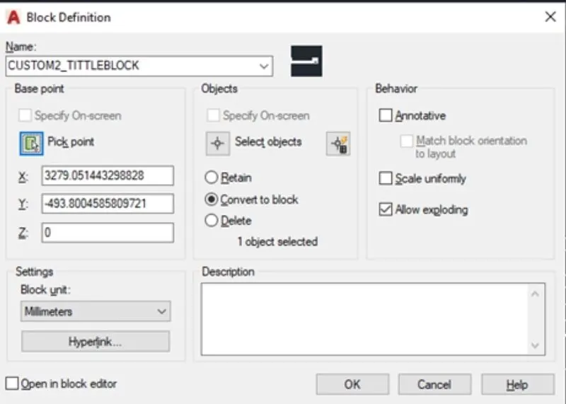
Creating a block
Type b in the command box for the block
Next give the name of the block
Next select the object and pickup point and next click on the creation of the block
2) AIM:
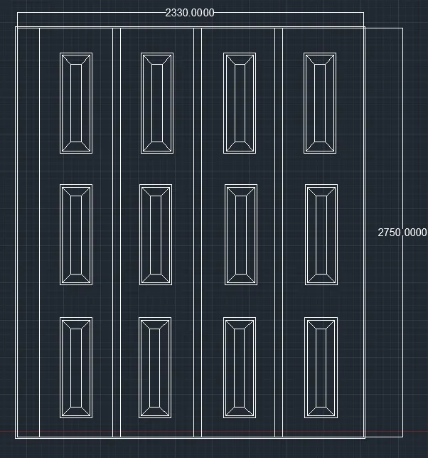
To create the door type for warehouse and after creating the blocks of this door type by using AutoCAD
Procedure:
STEP1:
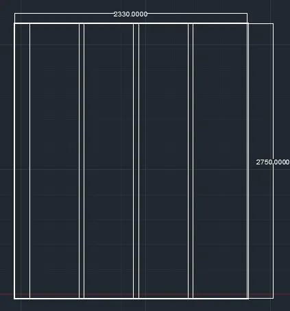
Take a rec command for rectangle and create a rectangle and create a rectangle of 2330 x 2750
Take a rec command for rectangle and create a rectangle
Next take the offset command and make a 300 mm offset from the four side rectangle
Now divide it into the four segments
STEP 2:
To create the doors type for warehouse
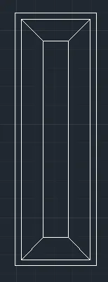
Take a rec command for rectangle and create a rectangle or creation of door
Next take the offset command command first and make the offset of 20 mm for creation of farm and 50 mm of offset and next take the line command join the form edge of the rectangle
STEP 3:
Now take a copy command and select the object and place it as per the requirement
Creation of the text . Type the MTEXT in the command box and type the text as door1
STEP 4:
Creating a block
Type b in the command box for the block
Next give the name of the block
Next select the object and pickup point and next click on the creation of the block
RESULT:
3)AIM:
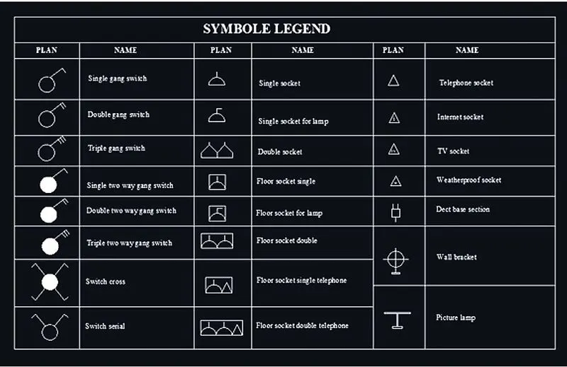
Create each symbol as a block with the name given in the legend. After creating the blocks arrange them in the legend using AutoCAD
Procedure:
STEP 1:
CREATION OF SYMBOLS
1) Single gang switch

2) Double gang switch

3) Triple gang switch

4)Single two way gang switch

5) Double two way gang switch

6)Triple two way gang switch

7)Switch cross

8)Switch serial

9)Single socket

10) Single socket for lamp

11) Double socket
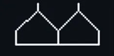
12) Floor socket single

13) Floor socket for lamp

14) Floor socket double
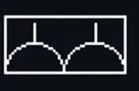
15) Floor socket single telephone

16) Floor socket double telephone
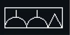
17) Telephone socket

18) Internet socket

19) T V socket

20) Weatherproof socket

21) Data base section

22) Wall Bracket

23) Picture lamp:

STEP 2:
Creating a block
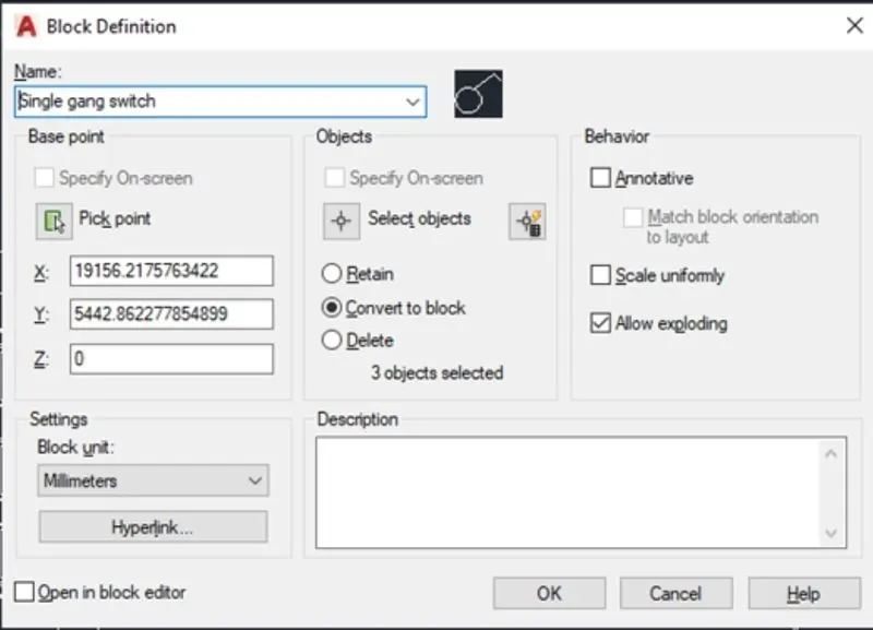
Type b in the command box for the block
Next give the name of the block
Next select the object and pickup point and next click on the creation of the block
Similarly convert all the symbols into blocks as mentioned above
STEP 3:
CREATION OF TABLE SYMBOL LEGEND
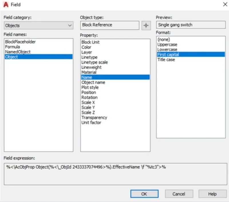
Take the insert command by typing I in the command box
Select the object option next take the selected object and then go filed option from the ribbon
Now select the object and place the name of the object
Result:
4) Creating the door type for residential building as a block.
Introduction:
To create the door type for residential building as a block using AutoCAD
Procedure:
STEP 1:
CREATION OF DOOR D1
Take a rec command for rectangle and draw with dimensions 2'-10" x 6'-11"
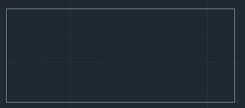
Next take a offset command of 2" and then 1" for the creation of frame
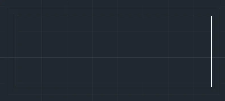
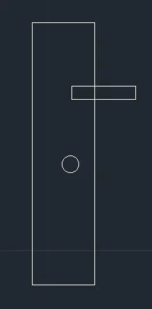
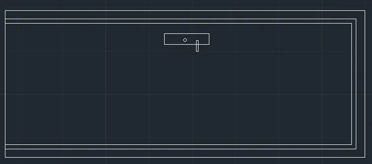
Now rotate it 90 degree
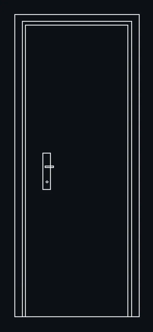
STEP 2:
Creating a block
Type b in the command box for the block
Next give the name of the block
Next select the object and pickup point and next click on the creation of the block
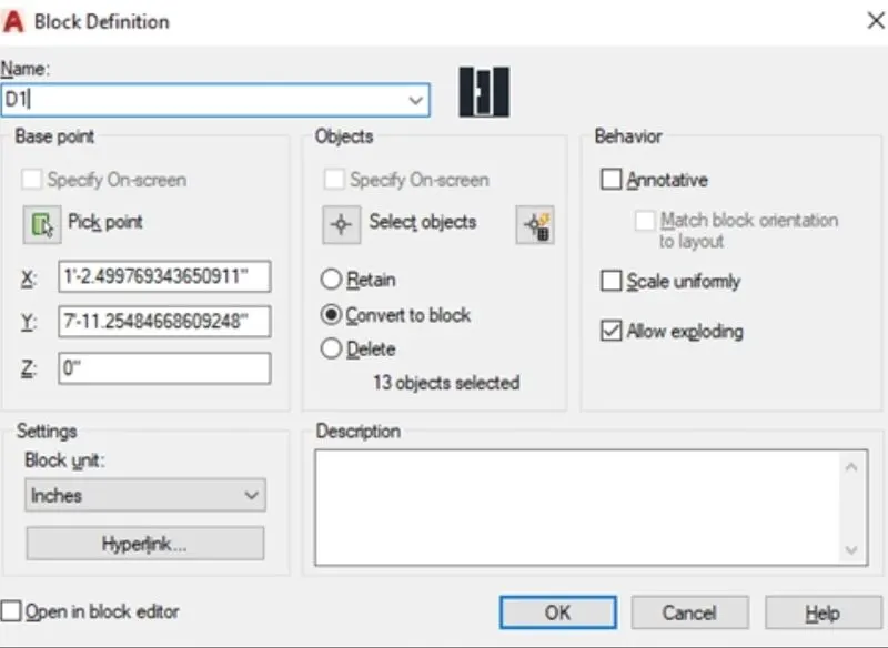
STEP 1:
CREATION OF DOOR D2
Take a rec command for rectangle and draw with dimensions 3'-4" x 6'-11"
Next take a offset command of 2" and then 1" for the creation of frame
Now draw another rectangle inside it and give the offset of 1" for the creation of frame
Next by increasing the line thickness draw a rectangle box of 6" x 6" and copy it
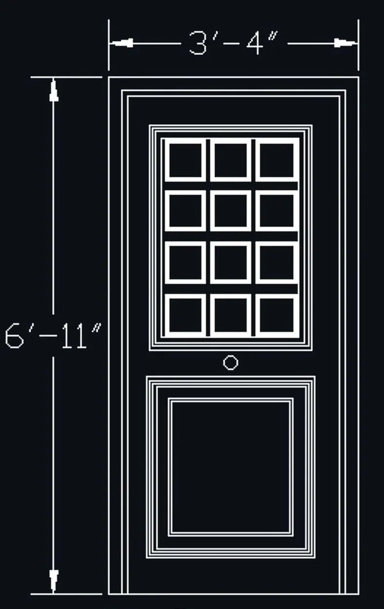
STEP 2:
Creating a block
Type b in the command box for the block
Next give the name of the block
Next select the object and pickup point and next click on the creation of the block
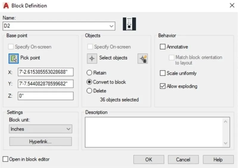
STEP 1:
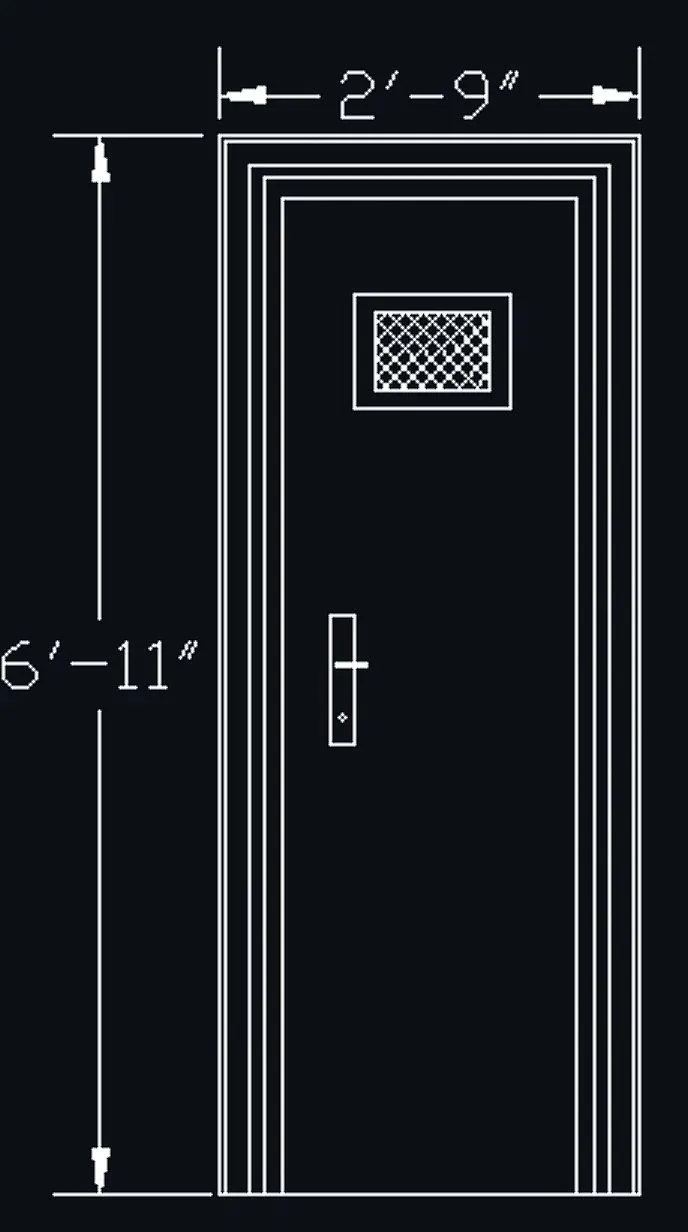
CREATION OF DOOR D3
Take a rec command for rectangle and draw with dimensions 2'-10" x 6'-11"
Next take a offset command of 2" and then 1" for the creation of frame
Now draw another rectangle inside it and give the offset of 1" for the creation of frame
Next take a rectangle of 1' x 1' and take offset 1"
Now hatch command and hatch inside the rectangle
STEP 2:
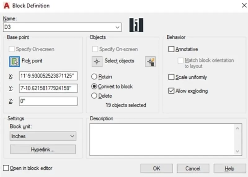
Creating a block
Type b in the command box for the block
Next give the name of the block
Next select the object and pickup point and next click on the creation of the block
STEP 1:
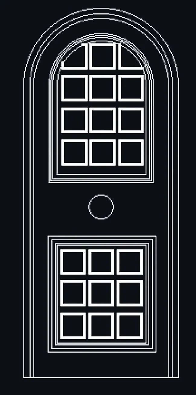
CREATION OF DOOR D4
Take a rec command for rectangle and draw with dimensions 3'-4" x 6'-11"
Next take a offset command of 2" and then 1" for the creation of frame
Now draw another rectangle inside it and give the offset of 1" for the creation of frame
Next take a circle command and draw a circle from one end to another
Trim the excess lines and take an offset command 2" and then 1" for creation of frame
Next by increasing the line thickness draw a rectangle box of 6" x 6" and copy it
STEP 2:
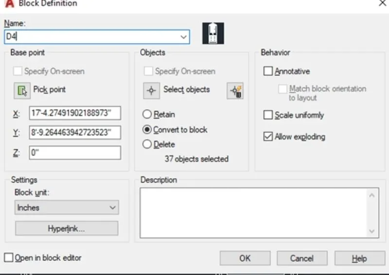
Creating a block
Type b in the command box for the block
Next give the name of the block
Next select the object and pickup point and next click on the creation of the block
STEP 1:
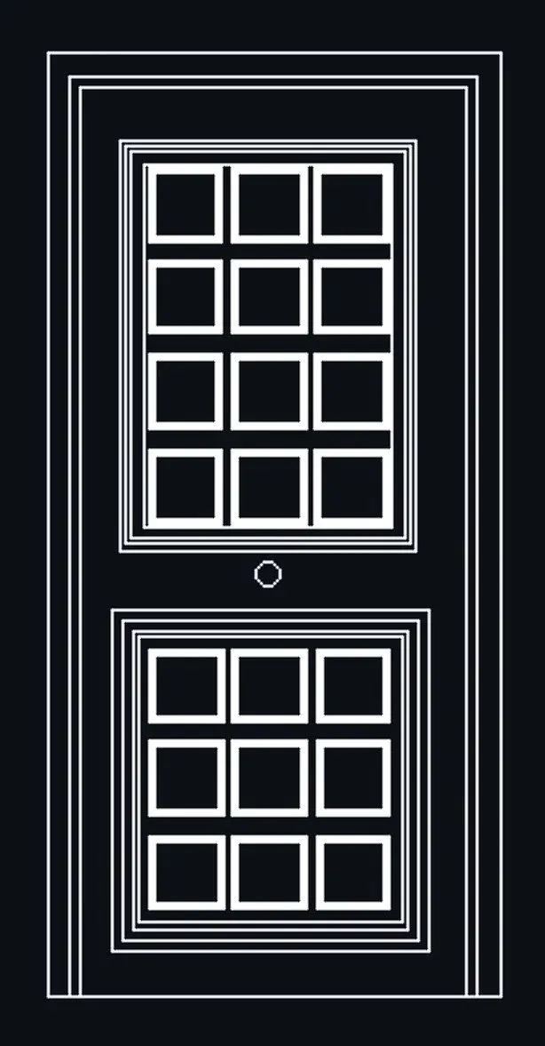
CREATION OF DOOR D5
Take a rec command for rectangle and draw with dimensions 3'-4" x 6'-11"
Next take a offset command of 2" and then 1" for the creation of frame
Now draw another rectangle inside it and give the offset of 1" for the creation of frame
Next by increasing the line thickness draw a rectangle box of 6" x 6" and copy it
STEP 2:
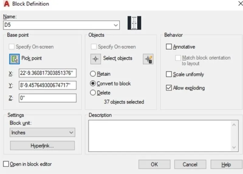
Creating a block
Type b in the command box for the block
Next give the name of the block
Next select the object and pickup point and next click on the creation of the block
STEP 1:
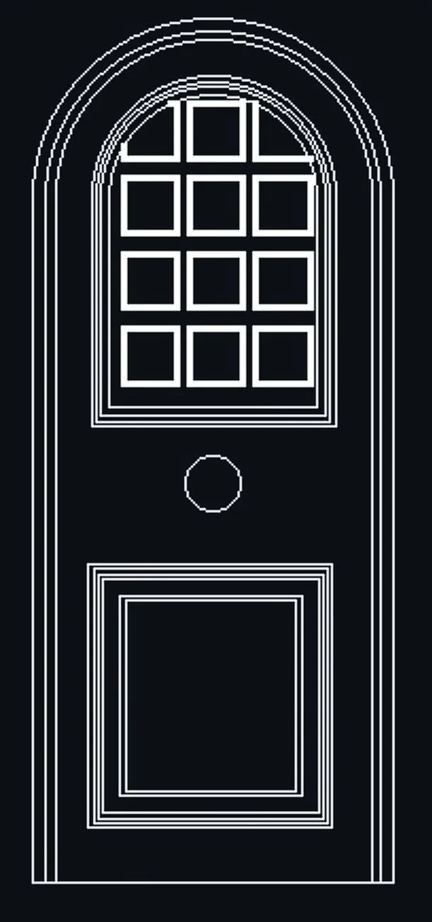
CREATION OF DOOR D6
Take a rec command for rectangle and draw with dimensions 3'-4" x 6'-11"
Next take a offset command of 2" and then 1" for the creation of frame
Now draw another rectangle inside it and give the offset of 1" for the creation of frame
Next take a circle command and draw a circle from one end to another
Trim the excess lines and take an offset command 2" and then 1" for creation of frame
Next by increasing the line thickness draw a rectangle box of 6" x 6" and copy it
STEP 2:
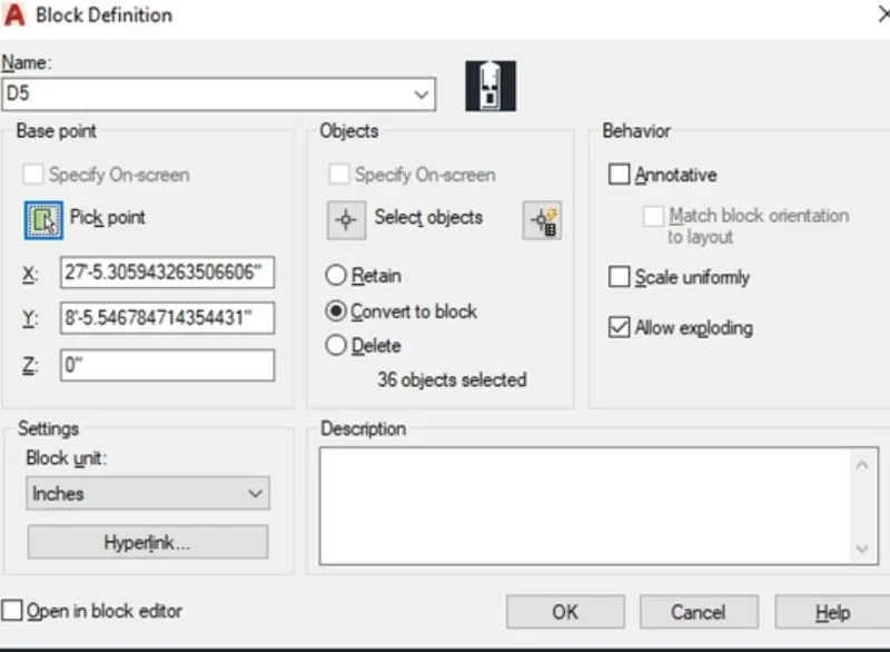
Creating a block
Type b in the command box for the block
Next give the name of the block
Next select the object and pickup point and next click on the creation of the block
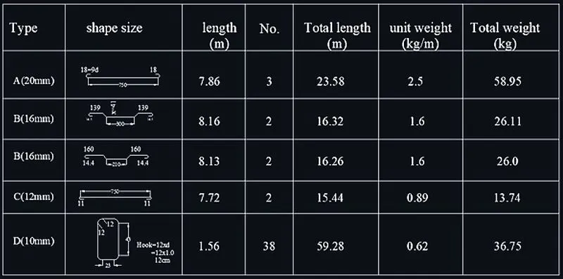
5. AIM:
Create each shape as a block as shown in the Figure. Save the block and insert them on the table
Introduction:
Create each shape as a block as shown in the Figure. Save the block and insert them on the table using AutoCAD
Procedure:
STEP 1:
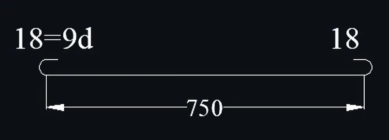
Creating of shape A-20mm
First take line command of length 750
Type C for circle command and make a circle of radius 9
Type TR for trim command and trim the extra lines and mirror it on the other side
Now take DIM command and mark the dimensions
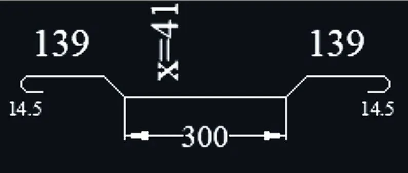
Creating of shape B-16mm
First take line command of length 300
At the end draw a line of length of 41 and join with the angle 45
From the end draw line of length 139
Type C for circle command and make a circle of radius 14.5
Type TR for trim command and trim the extra lines and mirror it on the other side
Now take DIM command and mark the dimensions
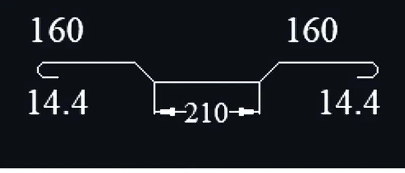
Creating of shape C-16mm
First take line command of length 210
At the end draw a line of length of 41 and join with the angle 45
From the end draw line of length 160
Type C for circle command and make a circle of radius 14.4
Type TR for trim command and trim the extra lines and mirror it on the other side
Now take DIM command and mark the dimensions
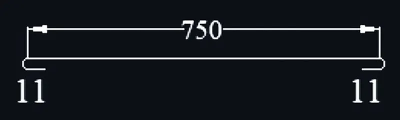
Creating of shape D-12mm
First take line command of length 750
Type C for circle command and make a circle of radius 11
Type TR for trim command and trim the extra lines and mirror it on the other side
Now take DIM command and mark the dimensions
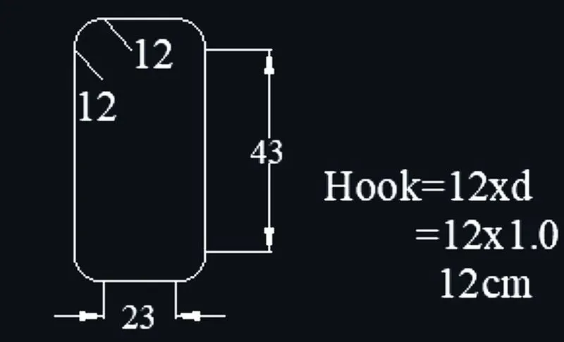
Creating of shape E-10mm
First take REC command and draw rectangle of dimensions 23 x 43
Type F for fillet command of radius 12
Now take DIM command and mark the dimensions
STEP 2:
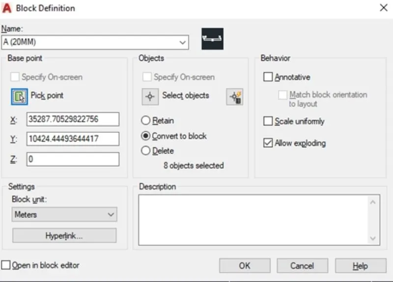
Creating a block
Type b in the command box for the block
Next give the name of the block
Next select the object and pickup point and next click on the creation of the block
STEP 3:
Now take a REC command and draw a rectagle
Take a Table command
Write TEXT using the MTEXT command
Take line command for making rows and columns
Take copy comman and copy the text and edit the text as per required
RESULT: