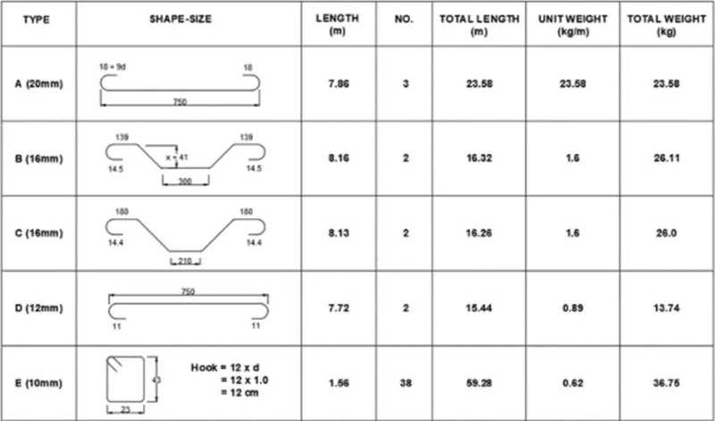
Creating Bar Bending schedule, Different Door types, and Creation of standard drawing templates using AutoCad
Ans 1. DRAWING TEMPLATES
Aim :- Create the templates as shown in Figures in AutoCAD.
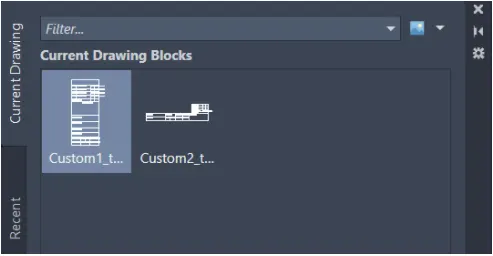
Introduction :- Create the templates as shown in Figures. Take the size of the title block as per industry standards or you can assume it as per the size of the paper. Use text and attributes wherever required. After creating the title block you need to save it as a block with names: Custom1_titleblock and Custom2_titleblock, respectively.
- The drawing is converted into blocks. For creation of block use the command BLOCk or type B in the command box.
- Give the name to block, select origin and the object of which block is to be made and parameters are given and then click OK button.
- For inserting a block, use command INSERT or type i in command box and choose the block to be inserted.
- The WBLOCK command saves the block as an AutoCad file which can then be used in any other AutoCAd drawing.
- The variable text should be inserted using the ATT (define attribute) command.
- Blocks make the drawing more consistent they are easy to work with, also saves time and also reduce the file size.
Procedure :-
- Create the following using the drafting tools.
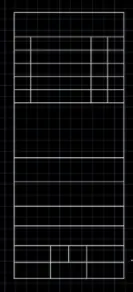
ii. Use MTEXT and give the text with Font as Times New Roman
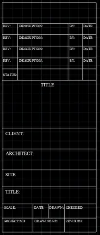
iii. Create the block of the given template and give the block as custom1_titleblock
iv. Create the following templates as shown using drafting tools
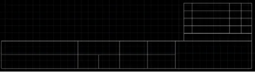
v. Add text given as follows

vi. Create the block of the given template and give the block name as custom2_titleblock
Result :-
The two templates can be inserted as block into drawings.
Ans 2. DRAWING DOOR TYPE FOR WAREHOUSE
Aim :- Create the doors type for warehouse as shown in Figures in AutoCAD.
Introduction :- Create the doors type for warehouse as shown in the Figure. You need to create each door type as per standard size or given dimensions. Create the blocks of this door type after creating them
- The drawing is converted into blocks. For creation of block use the command BLOCk or type B in the command box.
- Give the name to block, select origin and the object of which block is to be made and parameters are given and then click OK button.
- For inserting a block, use command INSERT or type i in command box and choose the block to be inserted.
- The WBLOCK command saves the block as an AutoCad file which can then be used in any other AutoCAd drawing.
- The variable text should be inserted using the ATT (define attribute) command.
- Blocks make the drawing more consistent they are easy to work with, also saves time and also reduce the file size.
Procedure :-
- Draw a outer rectangle of given dimension using rec command
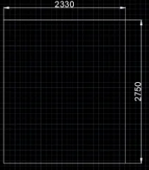
ii. Make different panels using polyline command, thickens the lines using PEDIT command
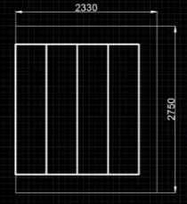
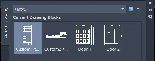
iii. Draw a handle of door and save it to block and name it, suppose DOor1
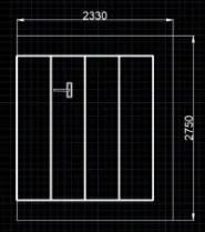
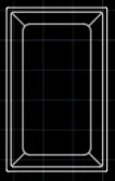
iv. Make the door panel using drafting tools
v. Now, make an array of 4X3 as shown below
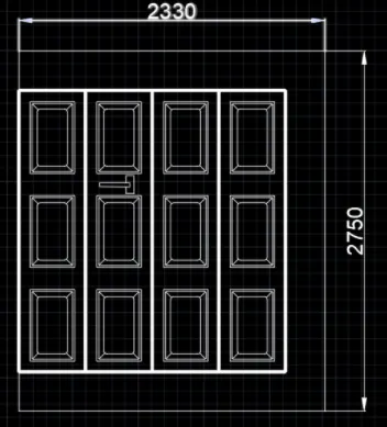
vi. Save the drawing as block with name suppose Door2
Result :-
The two door block type are made
Ans 3. LEGEND FOR SYMBOLS
Aim :- Create each symbol as a block with the name given in the legend as shown in Figures in AutoCAD.
Introduction :- Create each symbol as a block with the name given in the legend. After creating the blocks arrange them in the legend as shown in the Figure
- The drawing is converted into blocks. For creation of block use the command BLOCk or type B in the command box.
- Give the name to block, select origin and the object of which block is to be made and parameters are given and then click OK button.
- For inserting a block, use command INSERT or type i in command box and choose the block to be inserted.
- The WBLOCK command saves the block as an AutoCad file which can then be used in any other AutoCAd drawing.
- The variable text should be inserted using the ATT (define attribute) command.
- Blocks make the drawing more consistent they are easy to work with, also saves time and also reduce the file size.
Procedure :-
i. Make the table
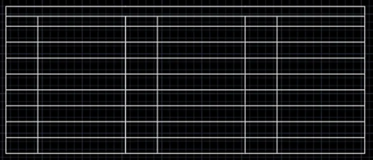
ii. Draw all symbols at one place and make block of each symbol with some specific name

iii. Insert the symbol at their place in the table as shown below
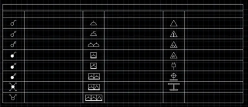
iv. Use FIELD command, insert name of each symbol corresponding to their resp. position, Change the font to Times New Roman and explode the text to remove the highlights

v. Add heading using MTEXT command
Result :-
The legend for symbol is made.

Ans 4. DOOR TYPE FOR RESIDENTIAL BUILDING
Aim :- Create the door type for residential building as a block as shown in Figures in AutoCAD.
Introduction :- Create the door type for residential building as a block. Save the name of the blocks as type. Use given dimensions or assume dimensions as per industry standards
- The drawing is converted into blocks. For creation of block use the command BLOCk or type B in the command box.
- Give the name to block, select origin and the object of which block is to be made and parameters are given and then click OK button.
- For inserting a block, use command INSERT or type i in command box and choose the block to be inserted.
- The WBLOCK command saves the block as an AutoCad file which can then be used in any other AutoCAd drawing.
- The variable text should be inserted using the ATT (define attribute) command.
- Blocks make the drawing more consistent they are easy to work with, also saves time and also reduce the file size.
Procedure :-
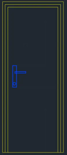
CREATION OF DOOR-1
- Create the door as shown below and convert it to block
- Name it as DOOR 1
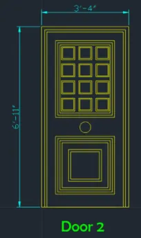
CREATION OF DOOR-2
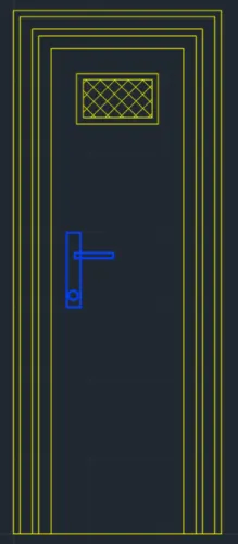
- Create the door as shown below and convert it to block
- Name it as DOOR 2

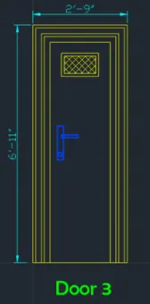
CREATION OF DOOR-3
- Create the door as shown below and convert it to block
- Name it as DOOR 3
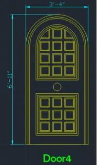
CREATION OF DOOR-4
- Create the door as shown below and convert it to block
- Name it as DOOR 4

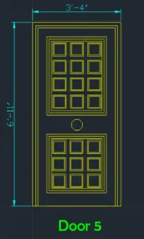
CREATION OF DOOR-5
- Create the door as shown below and convert it to block
- Name it as DOOR 5

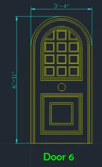
CREATION OF DOOR-6
- Create the door as shown below and convert it to block
- Name it as DOOR 6

Result :-
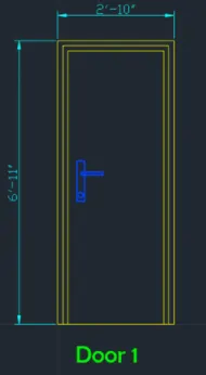
The different types of doors are shown below with dimensions as shown in the question figure
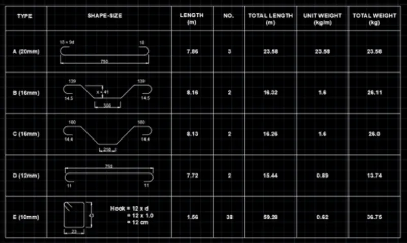
Ans 5. BAR BENDING SCHEDULE
Aim :- Create the each shape as a block as shown in Figures in AutoCAD.
Introduction :- Create each shape as a block as shown in the Figure. Save the block and insert them on the table as shown in the Figure.
- The drawing is converted into blocks. For creation of block use the command BLOCk or type B in the command box.
- Give the name to block, select origin and the object of which block is to be made and parameters are given and then click OK button.
- For inserting a block, use command INSERT or type i in command box and choose the block to be inserted.
- The WBLOCK command saves the block as an AutoCad file which can then be used in any other AutoCAd drawing.
- The variable text should be inserted using the ATT (define attribute) command.
- Blocks make the drawing more consistent they are easy to work with, also saves time and also reduce the file size.
Procedure :-
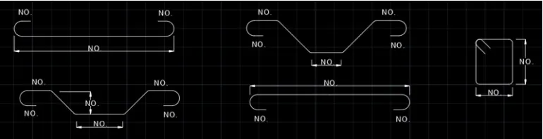
- Make the bar bending schedule diagram. Give the text using ATT command, under the tag NO was written and default value was kept as zero.
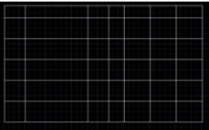
ii. Make the following table
iii. Add text using MTEXT command
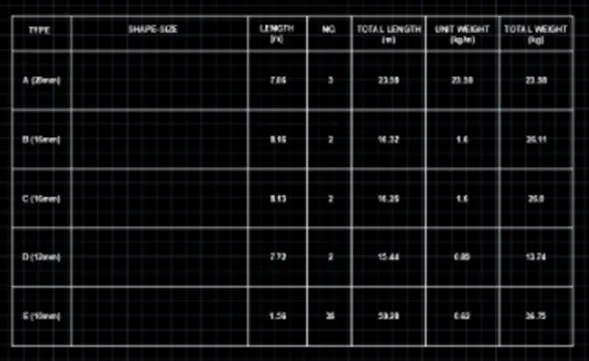
iv. Insert the block and give all the attributes their respective values
Result :-
The different types of bar bending schedule are shown below