Creating Bar Bending schedule, Different Door types, and Creation of standard drawing templates using AutoCad
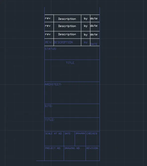
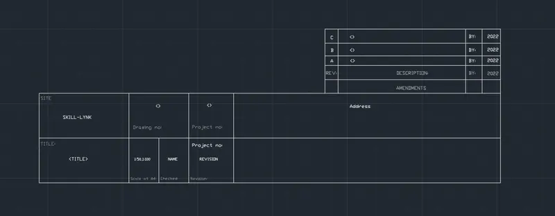
1. Create the templates as shown in Figures. Take the size of the title block as per industry standards or you can assume it as per the size of the paper. Use text and attributes wherever required. After creating the title block you need to save it as a block with names: Custom1_titleblock and Custom2_titleblock, respectively.
- AIM:
To create Custom1_titleblock and Custom2_titleblock using attributes and block commands.
- PROCEDURE:
Step 1:
In command prompt type L to draw lines.
In command prompt type Mtext to text the projections.
After texting, Colours can be changed from Properties.
In command prompt type > B to Create block.
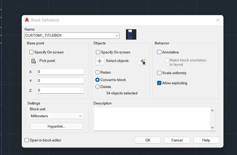
Block box opens and select the objects whichever to be under block property and create a name as Custom1_titleblock for the drawn section.
STEP 2:
In command prompt type L to draw lines.
In command prompt type Mtext to text the projections.
After texting, Colours can be changed from Properties.
In command prompt type > B to Create block.
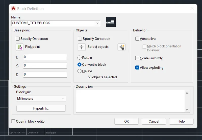
Block box opens and select the objects whichever to be under block property and create a name as Custom2_titleblock for the drawn section.
- RESULT:
2.Create the doors type for warehouse as shown in the Figure.You need to create each door type as per standard size or given dimensions. Create the blocks of this door type after creating them.
- AIM:
Create the doors type for warehouse as shown and to create the blocks of this door type after creating them by using AUTOCAD.
- PROCEDURE:
STEP 1:
In command prompt type > Units, and set as mm.
Set the limits as 0,0 and 100,100.
In command prompt type > L to draw the lines.
In command prompt type > rec to draft rectangle of dimensions required.
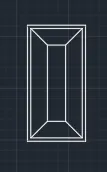
Use fillet command to curve the edges.
Give the dimensions of the door as per required.
In command prompt type > B to create the block of drawn door.
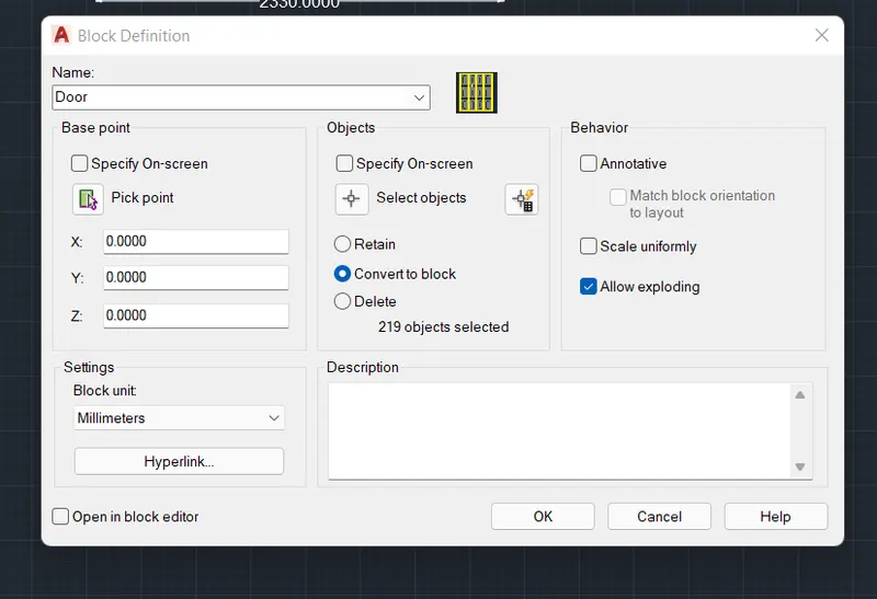
STEP 2:
In command prompt type > L to draw the lines.
In command prompt type > rec to draft rectangle of dimensions required.
Use fillet command to curve the edges.
Give the dimensions of the door as per required.
In command prompt type > B to create the block of drawn door.
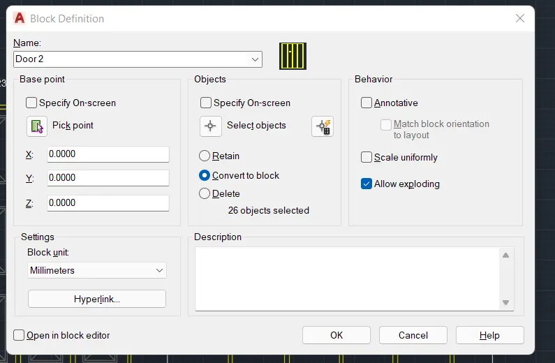
- RESULT:
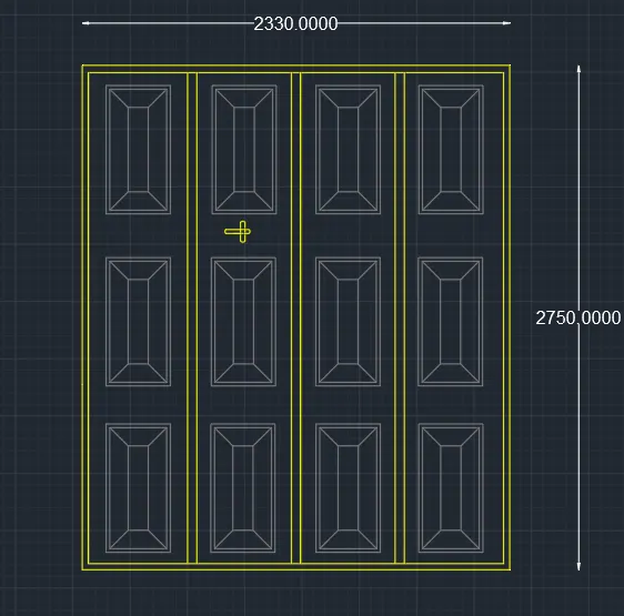
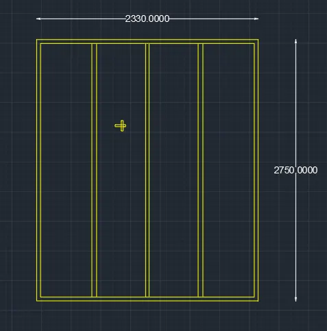
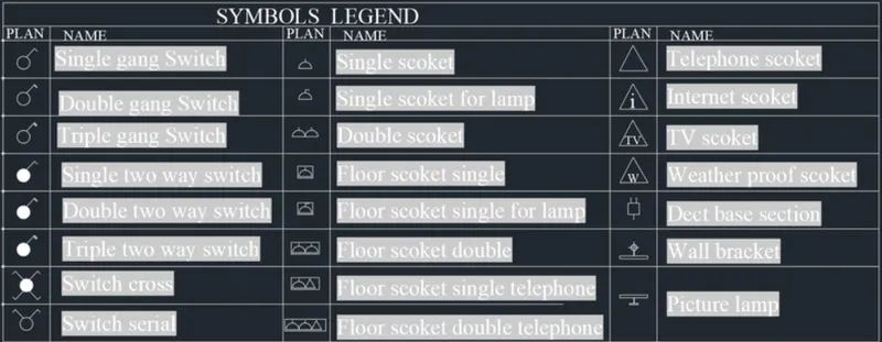
3. Create each symbol as a block with the name given in the legend. After creating the blocks arrange them in the legend as shown in the Figure.
- AIM:
To Create each symbol as a block with the name given in the legend.
- PROCEDURE:
In command prompt type > C to draw the circle.
Let the radius of circle be 65mm.
In command prompt type > L to draw the lines required.
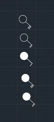
In command prompt type > Mtext to annotate the drawn segment.
In command prompt type > B to block the segment.
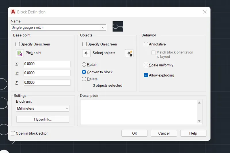
Or In ribbon bar > block > block edit.
Follow the same procedure for all the segments to be drawn.
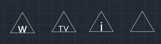
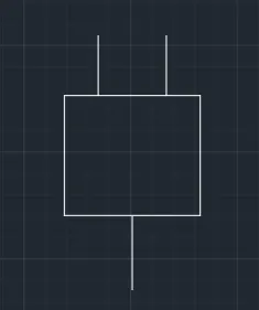
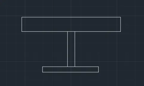

Select the drawn segment separately to Block the segment drawn.
In command prompt type > arc to draw arc for sockets segments.
In command prompt type > Mtext to annotate the drawn segment.
In command prompt type > B to block the segment.
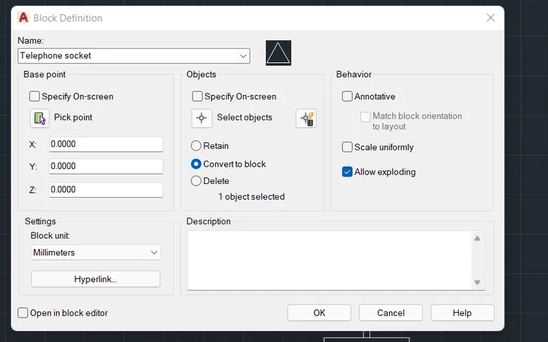
Or In ribbon bar > block > block edit.
Repeat the same procedure where ever it is required.
In command prompt type > I to insert the drawn segments from block properties.
RESULT:
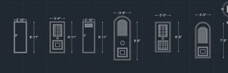
4. Create the door type for residential building as a block. Save the name of the blocks as type. Use given dimensions or assume dimensions as per industry standards.
- AIM:
To create door type for residential building as a block.
- PROCEDURE:
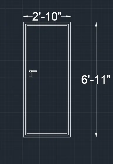
STEP 1:
In command prompt type > Units, and set as Inches.
Set the limits as 0,0 and 100,100.
In command prompt type > Z > A.
STEP 2:
In command prompt type L to draw lines.
In command prompt type Mtext to text the projections.
After texting, Colours can be changed from Properties.
In command prompt type > B to Create block.
Block box opens and select the objects whichever to be under block property and create a name as D1 for the drawn section.
STEP 3: In command prompt type L to draw lines.
In command prompt type Mtext to text the projections.
After texting, Colours can be changed from Properties.
In command prompt type > B to Create block.
Block box opens and select the objects whichever to be under block property and create a name as D2 for the drawn section.
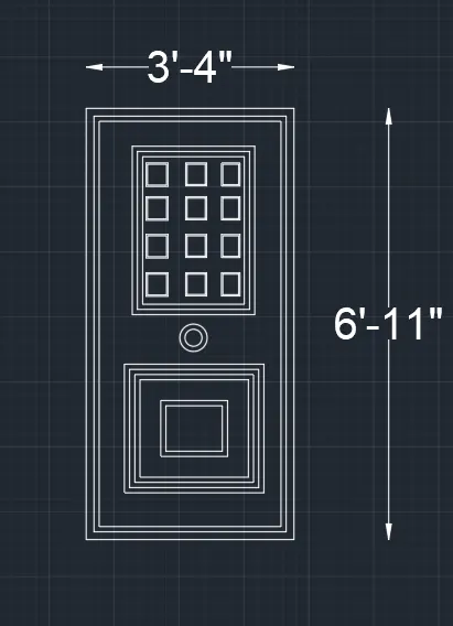
STEP 4:
In command prompt type L to draw lines.
In command prompt type Mtext to text the projections.
After texting, Colours can be changed from Properties.
In command prompt type > B to Create block.
Block box opens and select the objects whichever to be under block property and create a name as D3 for the drawn section.
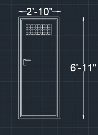
STEP 5:
In command prompt type L to draw lines.
In command prompt type Mtext to text the projections.
After texting, Colours can be changed from Properties.
In command prompt type > B to Create block.
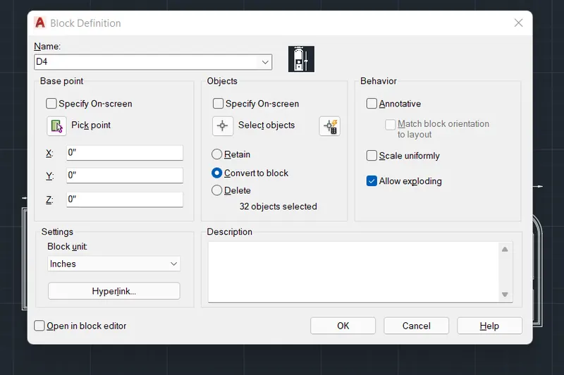
Block box opens and select the objects whichever to be under block property and create a name as D4 for the drawn section.
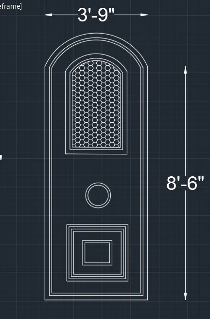
STEP 6:
In command prompt type L to draw lines.
In command prompt type Mtext to text the projections.
After texting, Colours can be changed from Properties.
In command prompt type > B to Create block.
Block box opens and select the objects whichever to be under block property and create a name as D5 for the drawn section.
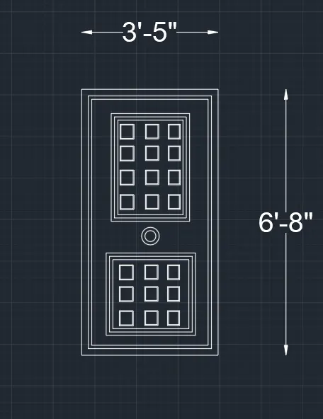
STEP 7:
In command prompt type L to draw lines.
In command prompt type Mtext to text the projections.
After texting, Colours can be changed from Properties.
In command prompt type > B to Create block.
Block box opens and select the objects whichever to be under block property and create a name as D6 for the drawn section.
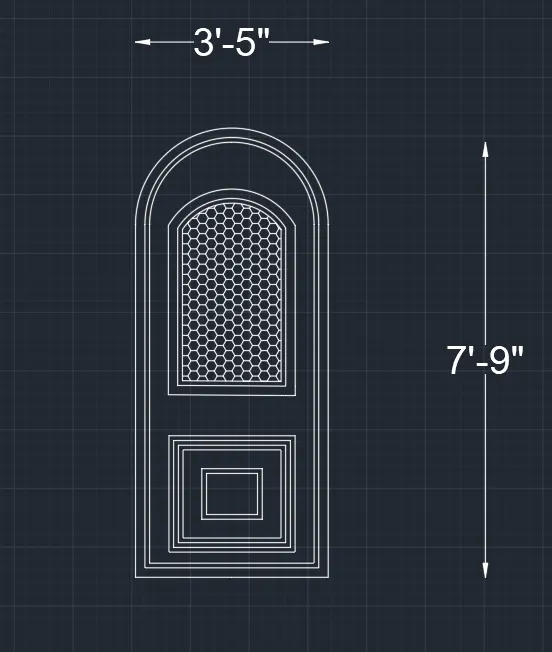
RESULT:
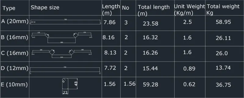
5. Create each shape as a block as shown in the Figure. Save the block and insert them on the table as shown in the Figure.
- AIM:
To Create each shape as a block as shown in figure in AUTOCAD.
- PROCEDURE:
STEP 1:
In command prompt type > Unit as metric and mm.
Set the limits as 0,0 and 100,100.
In command prompt type > Z > A.
STEP 2:
In command prompt type L to draw lines.
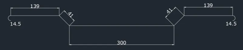
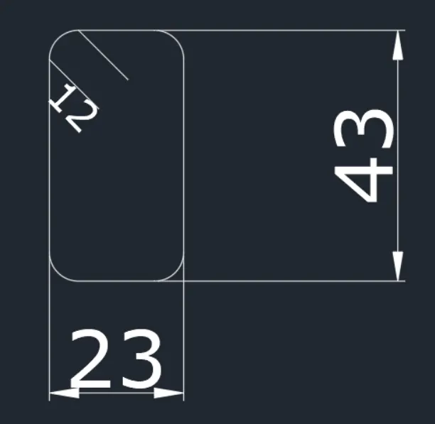
In command prompt type > polylines to draw desired polylines.
From Ribbon bar > select arc to draw arc where ever it is required.



In command prompt type table to insert the table.
In command prompt type Mtext to text the projections.
After texting, Colours can be changed from Properties.
In command prompt type > B to Create block.
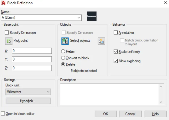
Block box opens and select the objects whichever to be under block property and create a name for the drawn section.
In command prompt type > I to insert the drawn segment from block property.
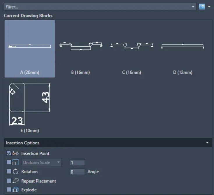
RESULT: