Creating Bar Bending schedule, Different Door types, and Creation of standard drawing templates using AutoCad
AIM & INTRODUCTION:
AIM:
- To create the templates, the doors type for warehouse, symbol as a block with the name given in the legend, the door type for residential building and shape as a blocks and insert them on the table.
INTRODUCTION:
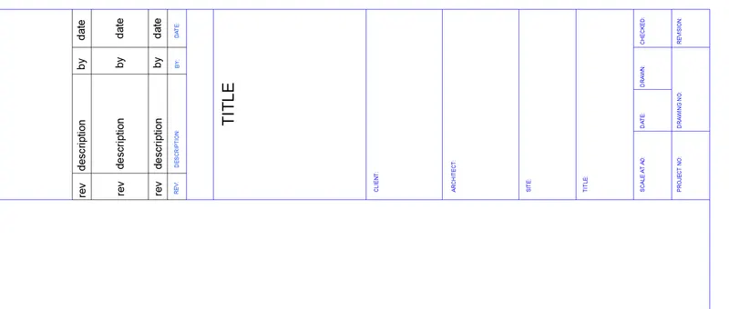
1. The template is the table arrangement with the title to specify about the drawing and which was provided in the corner of the page.
It is also used to describe the whole plans drawings which are drafted inside the sheet.
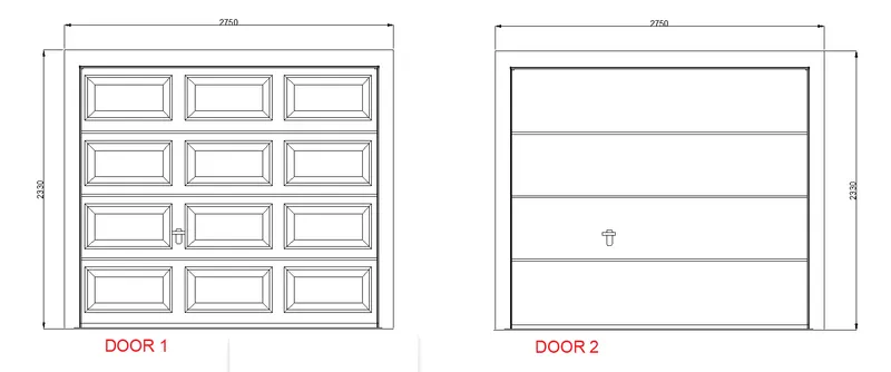
2. The two sides of the doors type for warehouse has been drafted with the name of door1 and door2.
The first drawing of the door can be seen with the front side design and the second drawing of the door can be seen with the front side design has not been provided.
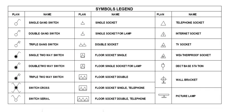
3. The legend has been created with the blocks of the symbols along with the table insertion.
The symbols are denoting the electrical items such as types as switches and sockets.
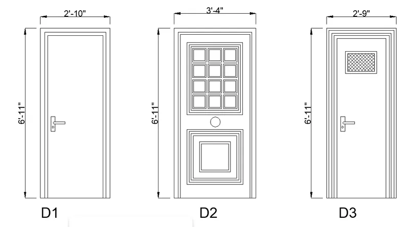
4. The door type for the residential buiding are drawn with the various types of the front elevation designs as a name of D1, D2, D3, D4, D5, D6.
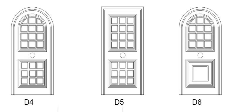
Some of the door type can be seen with the arc shaped at its top with door name of D4, D6 .
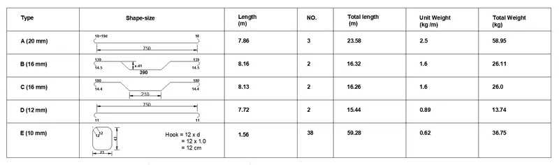
5. The shapes of the steel rebar are created and converted into the blocks and attached inside the table which was created with rebar properties.
PROCEDURE:
1. (A) Template with a block name as Custom1_titleblock :
- First the sheet sized rectangle Should be created with the "RECTANGLE" tool with dimensions as @210,297.
- Here the rectangle was created as A4 sheet with the dimension of 210mm x 297mm.
- The rectangle should be explode with the "EXPLODE" command before using offset command and then the spacing for the title block is allowed to separate from the right outer line of the rectangle with the "OFFSET" tool ,by assuming the distance as per the sheet length and width.
- Likewise the other divisions should also be offsetted as per the sheet length and width with the reference of the shown figure.
- Then the title should be created as attributes by using the command "ATTDEF" after filling the required name as values, then the attribute is allowed to place on the sheet.
- After creating all the attributes, it is allowed to be convert into a block by the command "BLOCK", through selecting and the base point of the required object and giving the name for the block as "Custom1_titleblock".
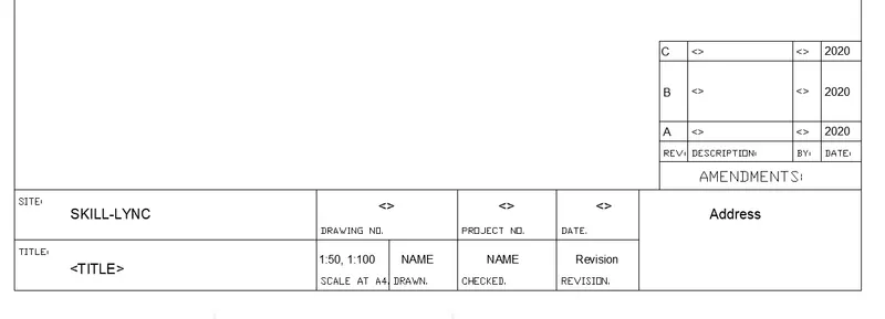
(B) Template with a block name as Custom2_titleblock :
- First the sheet sized rectangle Should be created with the "RECTANGLE" tool with dimensions as @210,297.
- Here the rectangle was created as A4 sheet with the dimension of 210mm x 297mm.
- The rectangle should be explode with the "EXPLODE" command before using offset command and then the spacing for the title block is allowed to separate from the bottom outer line of the rectangle with the "OFFSET" tool ,by assuming the distance as per the sheet length and width.
- Likewise the other divisions should also be offsetted as per the sheet length and width with the reference of the shown figure.
- Then the title should be created as attributes by using the command "ATTDEF" after filling the required name as values, then the attribute is allowed to place on the sheet.
- After creating all the attributes, it is allowed to be convert into a block by the command "BLOCK", through selecting and the base point of the required object and giving the name for the block as "Custom2_titleblock".
2. The doors type for warehouse as a blocks :
- The door1 was created by using "rectangle" tool with dimensions as @2750,2330.
- The other lines inside the door are offsetted from the rectangle to inside by assuming the values as per the reference with the shown figure.
- The 12 numbers of the small rectangular shapes inside the doors are drawn with the help of the tool "POLAR" by providing number of columns and rows required after creating one complete small rectangle with its offsetted line in it.
- The handle of the door was drawn with the line tool by assuming the line length as a reference of shown figure.
- The door2 was also created by using "rectangle" tool with dimensions as @2750,2330.
- The other lines inside the door are offsetted from the rectangle to inside by assuming the values as per the reference with the shown figure.
- The handle of the door was drawn with the line tool by assuming the line length as a reference of shown figure.
3. The legend with the symbols as blocks in the table:
- To create a legend, the table has been created by the command "table" and customising the number of title, header, columns and rows required.
- Here the 1 number of tile, 1 number of header, 12 number of columns, 8 number of rows are created.
- For the NAME HEADER the three continuous rows of a cell are needs to be MERGED with the merge option getting through by right clicking after selecting the required rows which has to be merged.
- The merging of the three rows helps to make the legend symbol names to be present inside the required cell.
- The legend symbols are then needs to be drawn and converted as a block with the name given in the legend.
- After creating the blocks it should be allowed to arrange in the legend as shown in the Figure for the reference.
4. (A) The doors type as a name of D1, D2, D3, for residential building as a blocks :
- The door named as D1 was created by using "rectangle" tool with dimensions as @2'10",6'11". Then the other lines inside the door are offsetted from the rectangle to inside by assuming the values as per the reference with the shown figure.
- The handle of the door was drawn with the line tool by assuming the line length as a reference of shown figure.
- The door named as D2 was created by using "rectangle" tool with dimensions as @3'4",6'11". Then the other lines inside the door are offsetted from the rectangle to inside by assuming the values as per the reference with the shown figure.
- The Designed front elevation of the D2 door was created by assuming the two inner rectangular shape outline.
- The upper rectangle is then filled with a small square like shape design and it created as one complete shape and then the number of shapes required to fill the upper rectangle inside the D2 was done by the help of the tool called "POLAR" by providing number of columns and rows required.
- Likewise the lower rectangle created inside the D2 was offsetted by assuming the distance as per the reference of the shown figure.
- The handle of the door was drawn with the "CIRCLE" tool by assuming the diameter as reference of shown figure.
- The door named as D3 was created by using "rectangle" tool with dimensions as @2'9",6'11". Then the other lines inside the door are offsetted from the rectangle to inside by assuming the values as per the reference with the shown figure.
- The Designed front elevation of the D3 door was created by assuming a inner rectangular shape outline with assumed offset distance along with the hatch filling using the "HATCH" command.
- The handle of the door was drawn with the line tool by assuming the line length as a reference of shown figure.
(B) The doors type as a name of D4, D5, D6, for residential building as a blocks :
- The door named as D4 was created by using "rectangle" tool as dimensions as door D2 . Then the other lines inside the door are offsetted from the rectangle to inside by assuming the values as per the reference with the shown figure.
- The Designed front elevation of the D4 door was created by assuming the two inner rectangular shape outline.
- Both the rectangles are then filled with a small square like shape design and it created as one complete shape and then the number of shapes required to fill the both rectangle inside the D4 was done by the help of the tool called "POLAR" by providing number of columns and rows required.
- The arch shaped finishing at the top of the D4 door was then created by filletting the two end lines of the door along with its offsetted inner lines using "FILLET" command and trimming the line which crossing the arch by using "TRIM' tool, before filletting the rectangle should be explode using the "EXPLODE" command.
- The handle of the door was drawn with the "CIRCLE" tool by assuming the diameter as reference of shown figure.
- The door named as D5 was created by using "rectangle" tool as dimensions as door D2 . Then the other lines inside the door are offsetted from the rectangle to inside by assuming the values as per the reference with the shown figure.
- The Designed front elevation of the D5 door was created by assuming the two inner rectangular shape outline.
- Both the rectangles are then filled with a small square like shape design and it created as one complete shape and then the number of shapes required to fill the both rectangle inside the D5 was done by the help of the tool called "POLAR" by providing number of columns and rows required.
- The handle of the door was drawn with the "CIRCLE" tool by assuming the diameter as reference of shown figure.
- The door named as D6 was created by using "rectangle" tool as dimensions as door D2 . Then the other lines inside the door are offsetted from the rectangle to inside by assuming the values as per the reference with the shown figure.
- The Designed front elevation of the D6 door was created by assuming the two inner rectangular shape outline.
- The upper rectangle is then filled with a small square like shape design and it created as one complete shape and then the number of shapes required to fill the upper rectangle inside the D6 was done by the help of the tool called "POLAR" by providing number of columns and rows required.
- Likewise the lower rectangle created inside the D6 was offsetted by assuming the distance as per the reference of the shown figure.
- The arch shaped finishing at the top of the D6 door was then created by filletting the two end lines of the door along with its offsetted inner lines using "FILLET" command and trimming the line which crossing the arch by using "TRIM' tool, before filletting the rectangle should be explode using the "EXPLODE" command.
- The handle of the door was drawn with the "CIRCLE" tool by assuming the diameter as reference of shown figure.
5. The table for properties and the shapes as a blocks :
- First the table has been created by the command "table" and customising the number of title, header, columns and rows required.
- Here the 0 number of tile, 1 number of header, 16 number of columns, 10 number of rows are created.
- For the SHAPE-SIZE HEADER the three continuous rows of a cells are needs to be MERGED with the merge option getting through by right clicking after selecting the required rows which has to be merged.
- The merging of the three rows helps to make the SHAPE BLOCKS to be present inside the required cell.
- Likewise the other header and other cells are needs to be merged to get the cell sizes as per the shown figure.d is
- The texts can be types inside the table wherever needs to be texed by double clicking in the cell.
- The Shapes are then needs to be created as per the shown figure and converted into blocks.
- After creating the blocks it should be allowed to arrange inside the table as shown in the Figure for the reference.
RESULT:
1. (A) Template with a block name as Custom1_titleblock :
- This below image of a template was cropped from the full size paper sheet created as per the shown figure.
- The template is the table arrangement with the title to specify about the drawing and which was provided in the corner of the page.
- It is also used to describe the whole plans drawings which are drafted inside the sheet.
(B) Template with a block name as Custom2_titleblock :
- This below image of a template was cropped from the full size paper sheet created as per the shown figure.
- The template is the table arrangement with the title to specify about the drawing and which was provided in the corner of the page.
- It is also used to describe the whole plans drawings which are drafted inside the sheet.
2. The doors type for warehouse as a blocks :
- The two sides of the doors type for warehouse has been drafted with the name of door1 and door2.
- The first drawing of the door can be seen with the front side design and the second drawing of the door can be seen with the front side design has not been provided.
3. The legend with the symbols as blocks in the table:
- The legend has been created with the blocks of the symbols along with the table insertion.
- The symbols are denoting the electrical items such as types as switches and sockets.
4. (A) The doors type as a name of D1, D2, D3, for residential building as a blocks :
- These door types for the residential buiding are drawn with the various types of the front elevation designs as a name of D1, D2, D3.
- The handle of the door was drawn by assuming the line length as a reference of shown figure.
- The handle of the door D2 was drawn by assuming the diameter value as reference of shown figure.
(B) The doors type as a name of D4, D5, D6, for residential building as a blocks :
- These door types can be seen with the arc shaped at its top with door name of D4, D6 .
- The handle of the doors were drawn by assuming the diameter value as reference of shown figure.
5. The table for properties and the shapes as a blocks :
- The shapes of the steel rebar are created and converted into the blocks and attached inside the table which was created with rebar properties.