Creating Architectural and Structural model with 3D rendering using REVIT
PROJECT
Creating the Complete Architectural and Structural Model of a G+7 Residential Building
AIM: To create the complete Architectural and structural model of a g+7 residential apartment building using Revit and to showcase the realistic views of the building through rendering different views.
INTRODUCTION:
Revit is a complete BIM (Building Information Modeling) tool that allows you to create every little building detail from floor plans to sections, elevations, 3d views, and structural framing of the building. Tools and commands included in the software make it very easy to store and present all the drawings related to a particular project in a lot less time than other 2d CAD tools. Thus, in this project, a complete multistory residential apartment building is modeled. At the same time, structural framing and 3d rendering of the building is also covered to showcase how exactly the building will look upon its completion.
PROCEDURE:
1) Select the type of structure you want to build from one of the three below:
a. Multi-Unit Residential Apartment
b. Office Buildings
c. School
ANS)
As mentioned in the aim and introduction, we have chosen a multistory apartment building for this project. The in-depth design of the building is carried out in the forthcoming project phases below:
2) Assume reasonable assumptions for geographic and location details for your project modeling. Based on assumptions and type of structure selected identify the modeling requirements from NBC.
ANS)
So, the locality we have chosen for this project is Thane, Maharashtra. Thane is a fairly large metropolitan region with numerous high-rise structures constructed across the city. Accordingly, below are the requirements for our project that we have checked up with the NBC guidelines to plan a safe and suitable multistory residential apartment building in the selected region.
Plot Dimensions:
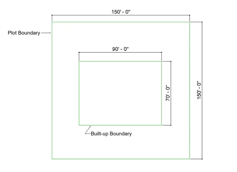
We have a 150 feet by 150 feet (150' x 150') plot available at our site. Hence, relevant building details are decided in accordance with the NBC guidelines below:
FAR (Floor Area Ratio):
So, according to the Development Control Regulations - THANE, we have the value of FAR as 2 in the region.
Therefore,
Total plot area = 150' x 150' = 22500 sqf.
FAR = 2
Total buildable area = 45000 sqf.
Built-up Area Calculation:
As already been discussed, we have a floor area ratio of 2 for our project making a total of 45000 sqft. available to be built.
And after summarizing the margin and setback requirements in our locality, we have come to settle down the total buildable area at 90' x 70' feet which is a total of 6300 sqft. at the ground level. Moreover, we are leaving the entire ground floor area for parking and thus the built-up will be calculated for 7 stories only.
Therefore,
Total building built-up = 6300 x 7 = 44100 sqft. < 45000 permissible sqft. Hence, OK.
Building Height:
So, the National Building Code or NBC regulates the building height based on the width of the road adjacent to the project site.
And in our case, we have a 60 feet wide two-way road adjacent to the plot.
Hence, According to the NBC,
Permissible building height = 1.5 time road width = 1.5 x 60' = 90' feet.
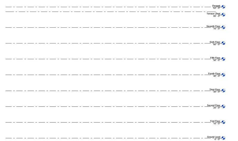
And we have decided to go ahead with the G+7 structure with 10' high floors and a 3' high parapet wall.
Therefore, total building height = 83' which is < permissible 90'. Hence, OK.
Project Levels as per the NBC Guidelines
Plot Boundary and Built-up Area Settings as per the Calculations Carried out
3) Using the structural model, include the following components based on the type of structure selected
a. Foundation – Isolated / Wall/Matt Foundation
b. Columns
c. Beams Connected to Columns
d. Roof Framing/ Truss
e. Floor / Decks
f. Floor Openings for Elevators and Stairs
ANS)
Before setting up the structural frame, we have to complete the Architectural layout of our building. Further, as per the grids formed through the floor plans, we will prepare the structural model of our building. Hence, the Architectural typical floor plan of our multi-unit residential building is drawn in relation to the space available at our hands as per the built-up requirements.
Architectural Layout of the Project:
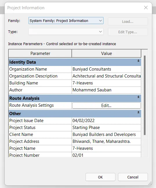
- Input the project information
- Go to the Manage tab and click on project information.
- A dialogue box will open where you can enter your project details inside the columns.
- Thus, we have entered the following building details into our project.
- Divide the available space and create the wall network
- As we have a total of 90' x 70' built-up space available at our hand, we have divided it into two sections up and down with a small central portion for accessibility.
- And between those two sections, we have left the central portion for stairs, lifts, and passage of the building.
- Now, you can create the wall network using the wall command the shortcut for which is "WA".
- Also, keep the NBC specifications for room sizes by your side while creating the wall network.
- Thus, keeping in mind the NBC specified room dimensions, you can divide the space smartly to create the Architectural layout of a single flat.
- You will also need to keep in check the ventilation and accessibility requirements for each building unit.
- And once you complete a single flat, you can then go ahead to add more flats based on the area available within the built-up space.
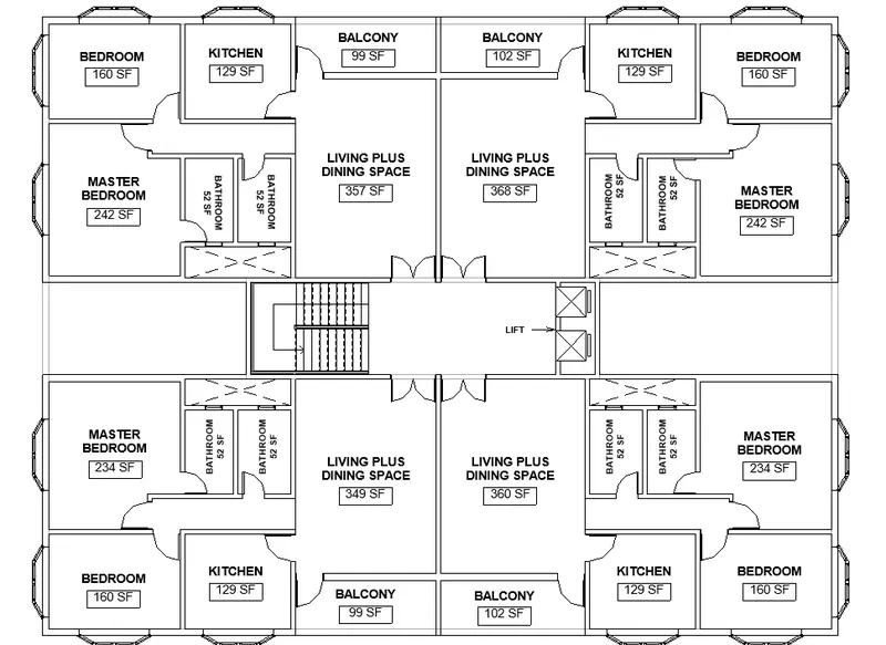
- For our project, we have accommodated four 2BHK apartments with a balcony and a master bedroom on every floor.
- After completing the floor plan, you can now include the room tags to showcase your area division within different rooms to complete the typical floor plan.
- Moreover, you can include all the relevant families into your project like doors, windows, lifts, etc. based on your room sizes.
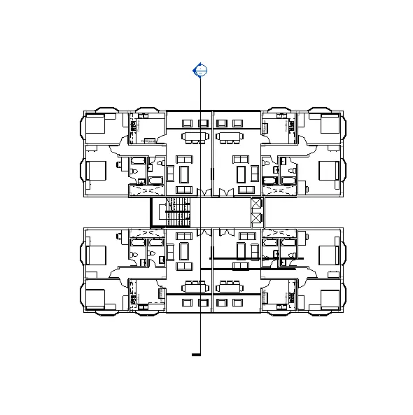
- Typical floor plan from 1st to 7th floor is inserted below:
- Creating the grid system
- Now that we have created the typical floor plan, we can draw the grid system cutting through the wall center which will act as the benchmark while preparing the structural framing of the building.
- To create grids, you can go to the Architecture tab and then click on the grid option or you can simply type the shortcut GR.
- So, we need to create transverse and longitudinal grids that intersect each other at certain points where we have to place our columns.
- Also, you need to name the grids appropriately for reference purposes while framing the structural model.
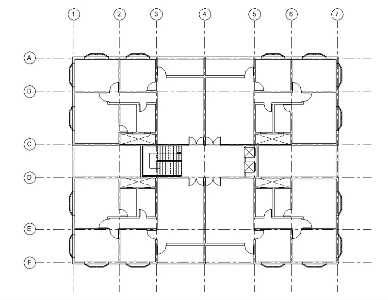
Thus, this is the grid system and now we can go ahead with the structural framing of our building.
STRUCTURAL FRAMING OF THE BUILDING:
- Open up a new structural template
- For creating the structural frame, you need to first open up a new project with the structural template in Revit.
- Also, you need to make sure to link your Architectural model for which you need to prepare the structural framework.
- The complete procedure to link the Architectural file to your structural project is discussed in details below:
- Link your Architectural file to the Structural model
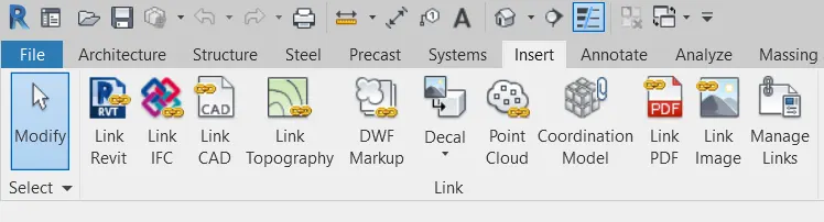
- Go to the insert tab and click on the Link Revit option.
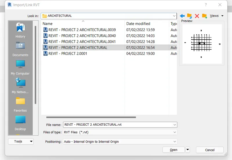
- Then, browse for your Architectural project and click on open.
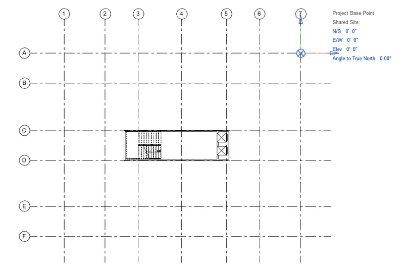
- But first, you need to set up the project base point which will be shared between both models.
- To set up the project base point, go to Manage>project location> specify coordinates> NS-0' 0" & EW-0' 0".
- Now go to the visibility settings and check the project base point.
- After that, set it up at 0-0 to match it with your project coordinates.
- Bring up the grid system into your structural model
- Go to copy monitor from the collaborate tab.
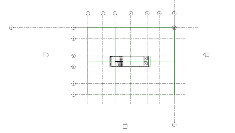
- Select the Revit link and select the object you want to copy into your project.
- So, select all the grids precisely and then click on finish.

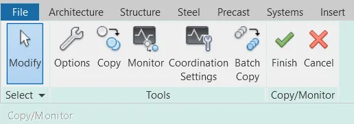
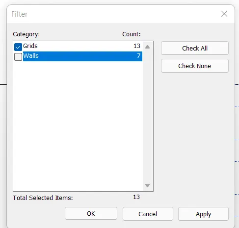
And thus, grids have been copied successfully into your structural template.
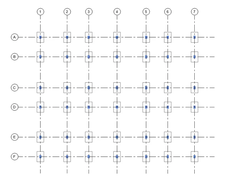
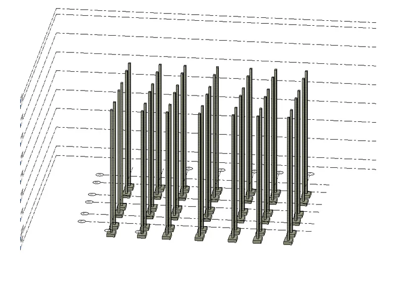
- Pace columns at the grid intersections
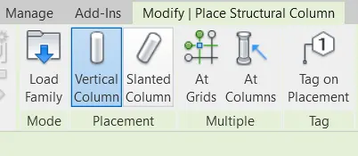
- From the structural tab, click on columns and select vertical columns.
- Then, select the "at grids" option to place them precisely on the grids.
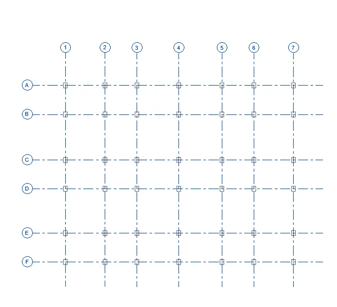
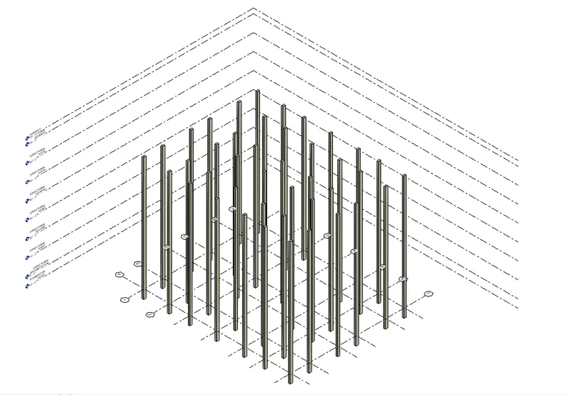
- Select all the grids and set up the column's base and top constraints as per the project requirements.
- Hence, columns have been successfully placed.
- Attach isolated footings to all columns
- Go to the Structure tab and click on the isolated footings.
- Choose the at columns option while placing footings.
- Select all the columns and complete the footing location.
- Locate the beams based on the columns network
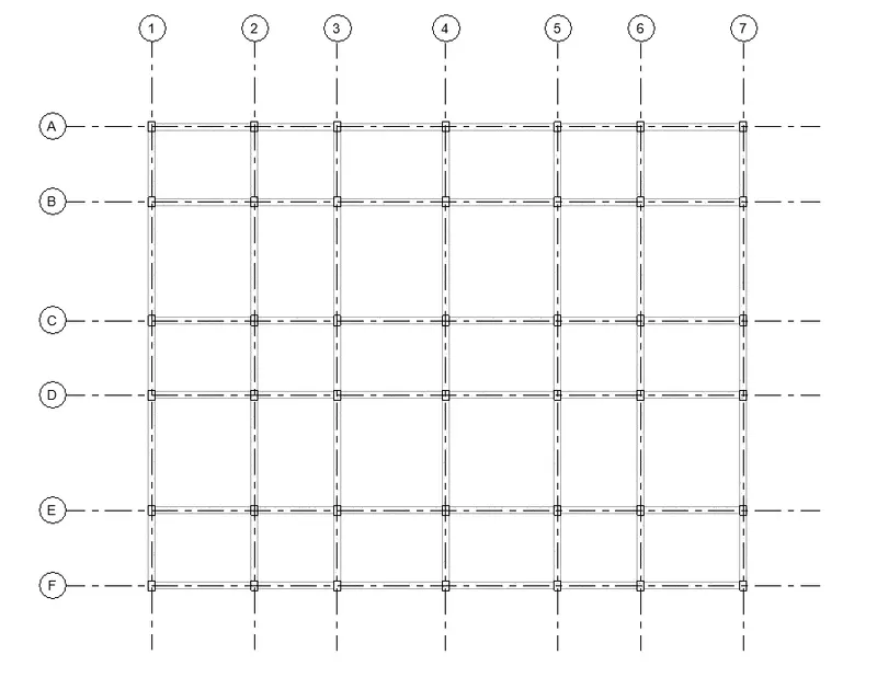
- Select beams from the Structure tab.
- Click on the at-grids option.
- Select all the grids and click finish to complete the beam diagram.
- Make sure to choose the correct floor level and height for the beam as per the NBC guidelines and scope of your project.
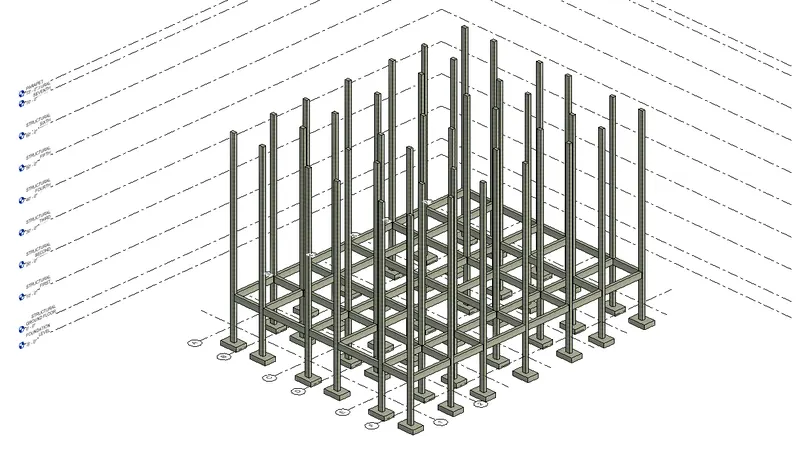
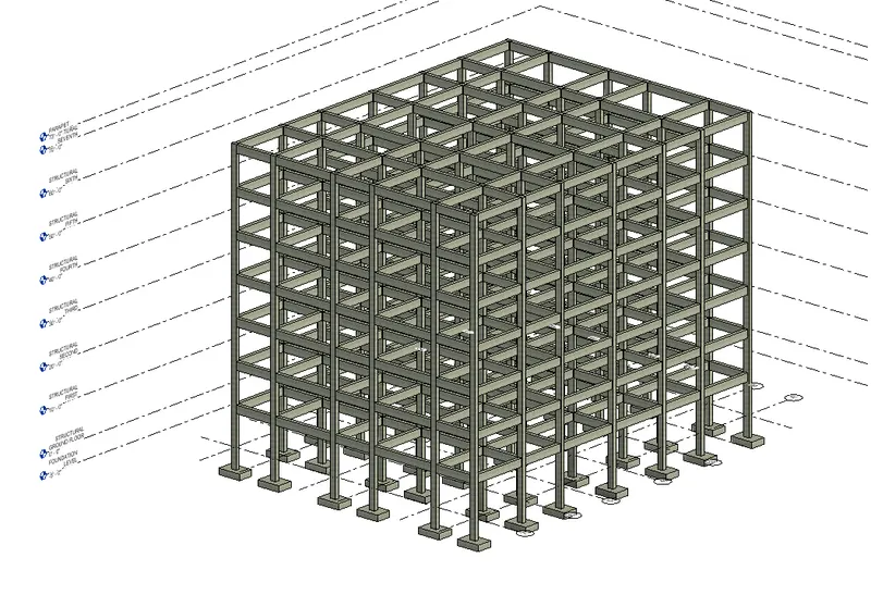
- Copy down the beam network up to the desired floor levels.
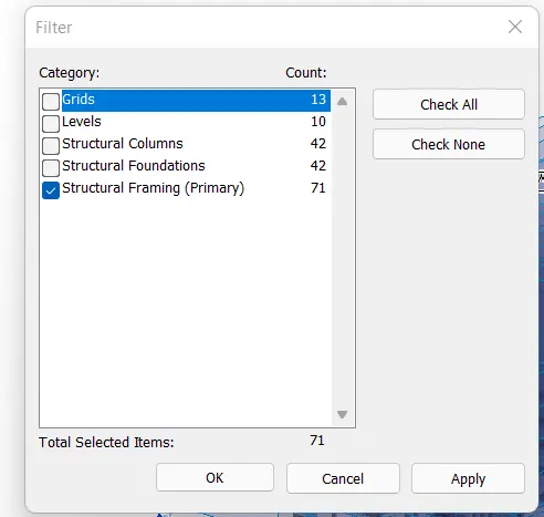
- Copy the entire Structural model and filter out the beam network.
- Copy it to the clipboard and then click on the paste option.
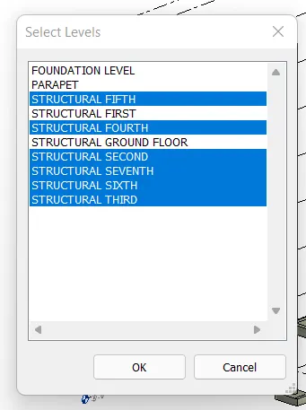
- Select the align to selected levels from the paste dropdown.
- Select all the levels you want your beams to be placed in and click ok.
- Incorporate the Structural floors into your frame
- Go to Structure and click on the floor.
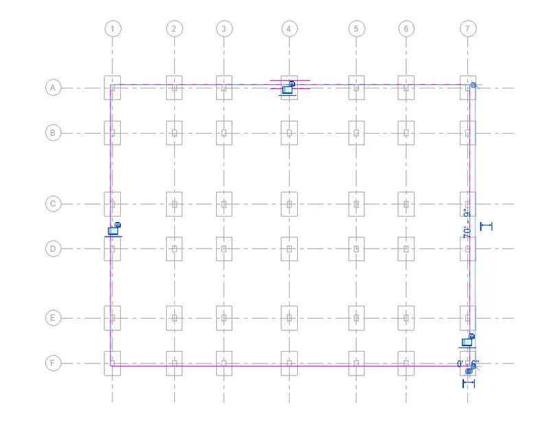
- Sketch the floor boundary manually based on the grids.
- Make sure all the boundaries of the floor connect and click on finish.
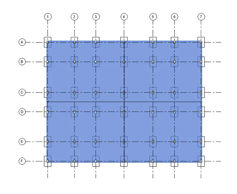
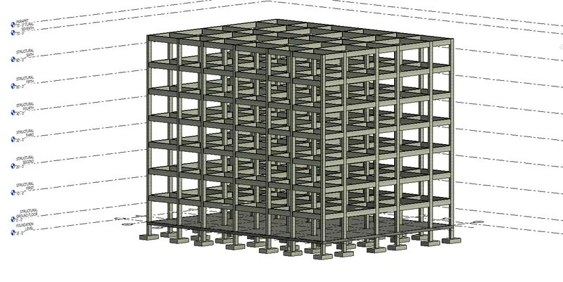
- Copy the Structural floor on all levels
- Select the floor> to copy it to the clipboard.
- Click on the paste dropdown and choose to align to selected levels.
- Select the desired levels and click apply and then ok to complete the procedure.
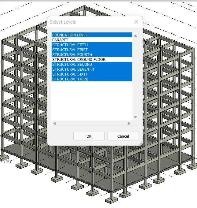
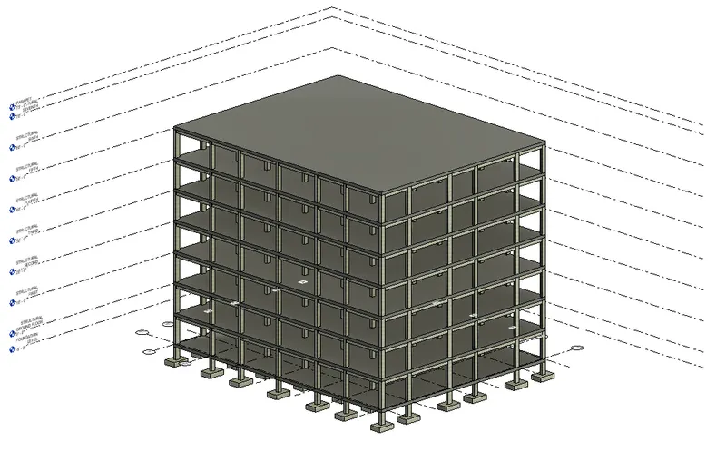
- Make shaft openings for the staircase and lifts
- Go to the opening tab and click on shaft opening.
- Draw the shaft sketch manually based on the staircase structure and the lift pit.
- Select the appropriate base and top constraints for the shaft and finish the process.
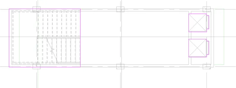
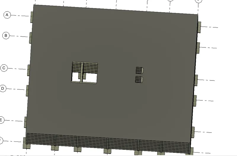
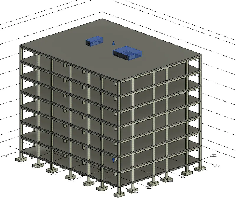
Thus, the overall Structural framing of our building has been completed.
4) Using the architectural model, include the following components based on the type of structure selected
a. Wall Layout with appropriate material and finishing
b. Exterior façade with fancy finish
c. Interior partition walls to size rooms
d. Components to add details to a room ( Desk, Chair, Lighting, Plumbing fixtures)
e. Add components such as stairs Elevators
f. Have at least one side of the building with curtain walls and glass panels
g. Include interior and exterior lighting fixtures
h. Place proper topographic components from outside ( Trees, Parking, Plants) to add details to the model
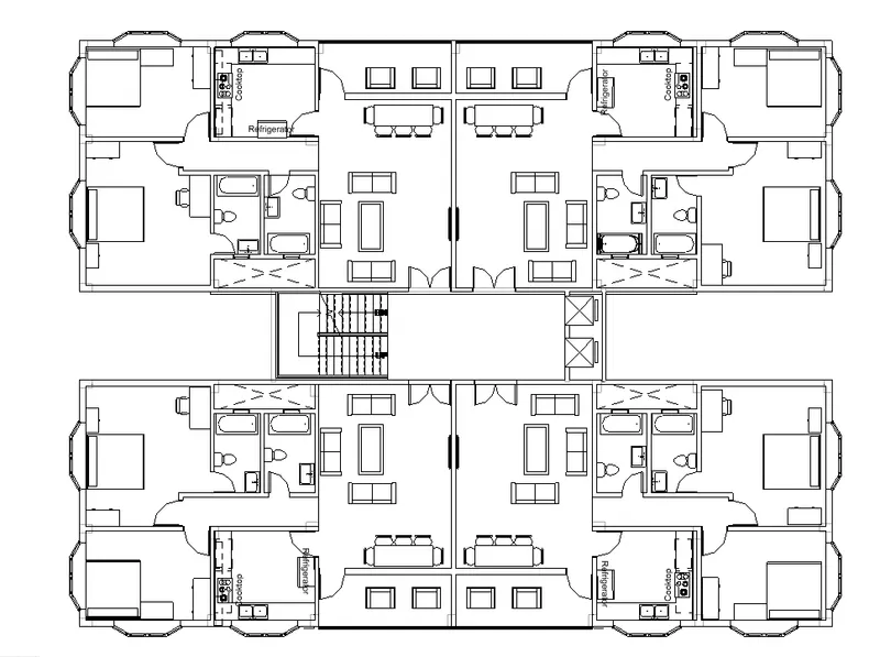
- Add up the Architectural components and plumbing fixtures into the model
- Go to the insert tab and click on the load family option.
- Browse the files and look for the required components in accordance with the room dimensions inside your building.
- The most common family types you need to include are furniture, plumbing fixtures, windows, doors, kitchen appliances, and special equipment.
- Once you load all the components, you can start dragging them into the position inside your building.
- Also, you can adjust their location by moving them around using arrow keys on your keyboard.
- Moreover, you need to make sure of the accessibility, ventilation, and proper sunlight access into the building while placing your furniture and other details.
- Assign the material properties to all your walls and floors
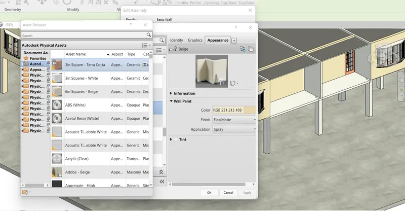
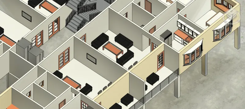
- After locating all your furniture and plumbing fixtures, go ahead and assign the appropriate materials to your exterior walls, interior walls as well as your floors.
- To do that, simply click on the wall > go to edit type > click on the structure > material browser will open up.
- From the same material browser, search for the required materials and hit apply.
- Follow the same procedure to allocate materials to all your Architectural walls and floors.
- Connect the staircase up to the top floor level and create a stair tower
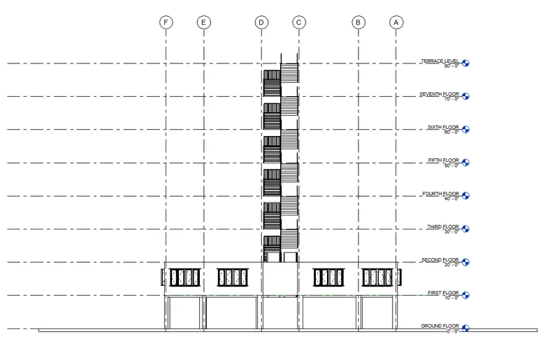
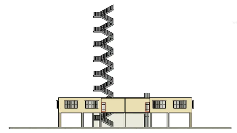
- Select your stair model and look for the connect option in the modify panel.
- Click on the connect option to make your stairs reach the top of the building.
- But make sure you are in one of your elevation windows as you cannot connect your stairs from floor plans.
- So, when you are in the elevation view and have clicked on the connect option, now you can select all the levels you want your stairs to go up to.
- Once you finish clicking all the levels, hit the finish and complete the stair tower.
- Copy the typical floor plan up to the seventh floor
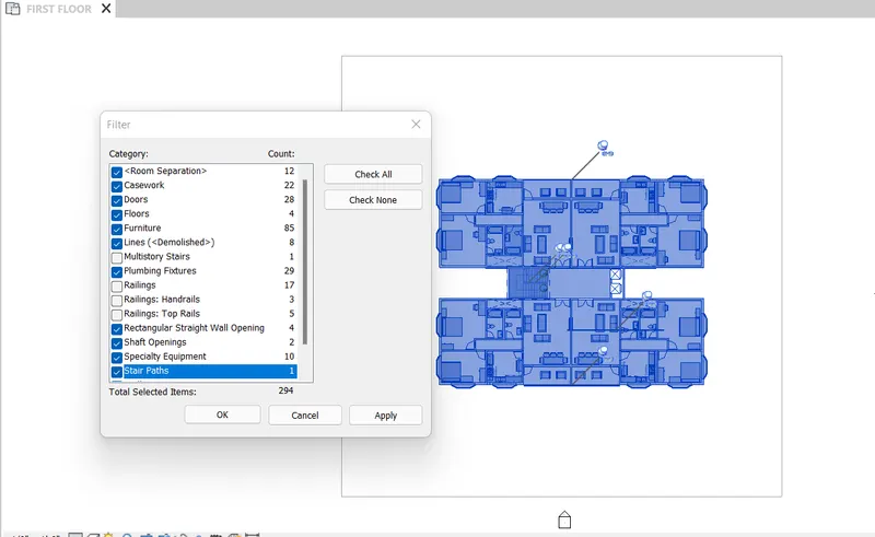
- Select the entire floor plan with all of the Architectural components and plumbing fixtures.
- Make sure to filter out the multistory stair tower from the selection as it can not be copied up.
- After filtering the selection, copy it to the clipboard.
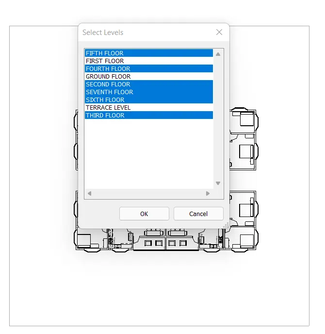
- Then, go to the paste dropdown and choose to align with the selected levels option.
- Select all the levels from second to seventh and click OK.
- After clicking apply and ok, it will take roughly 5-10 seconds and your floor plan will be aligned with all your levels.
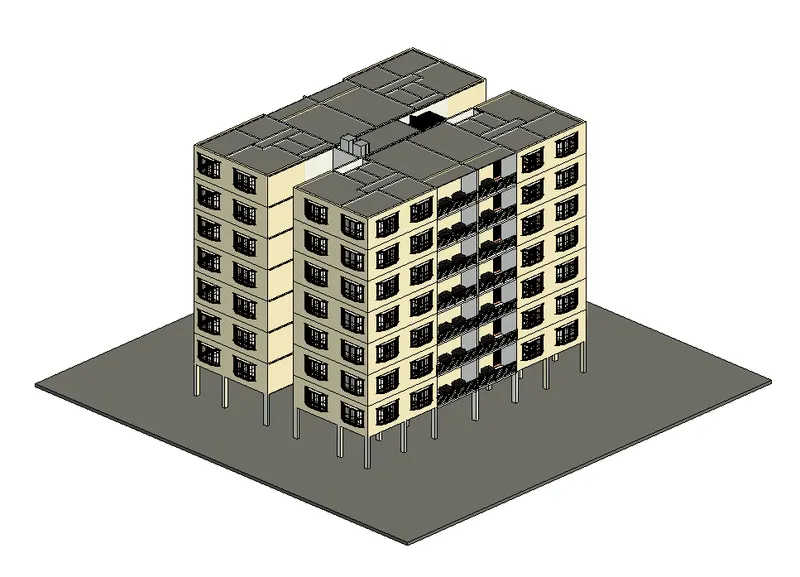
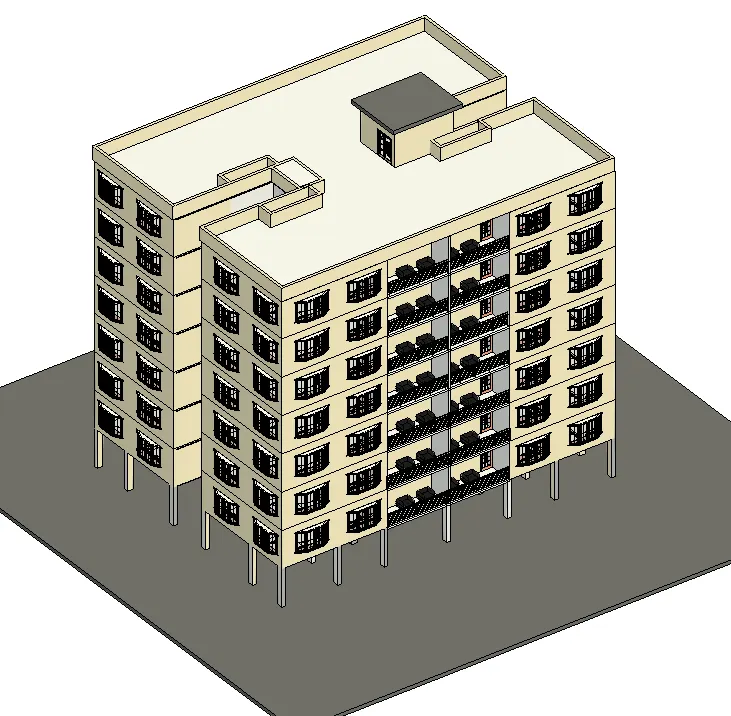
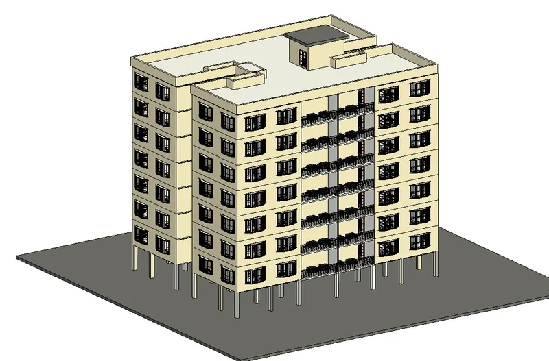
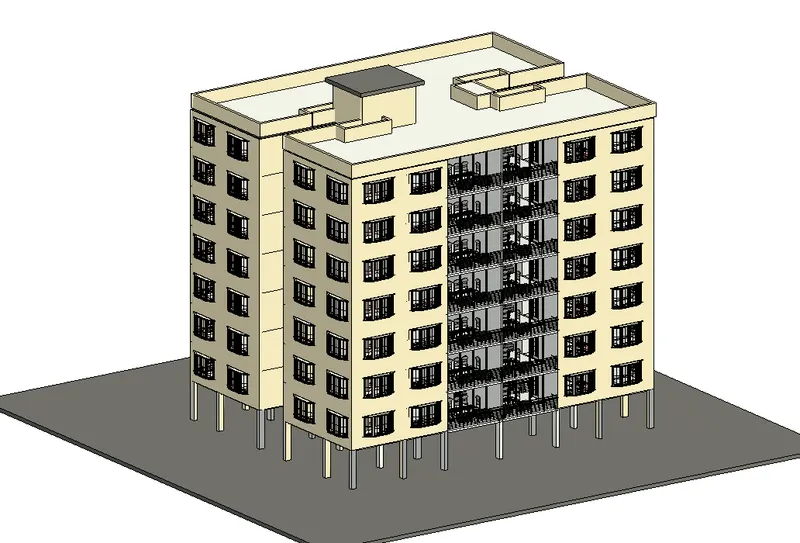
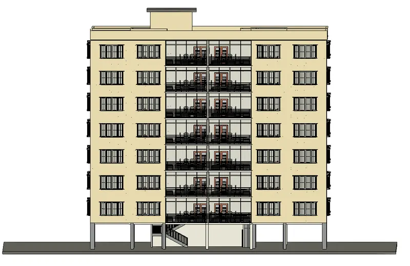
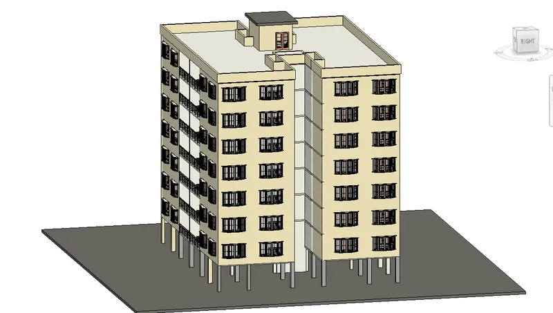
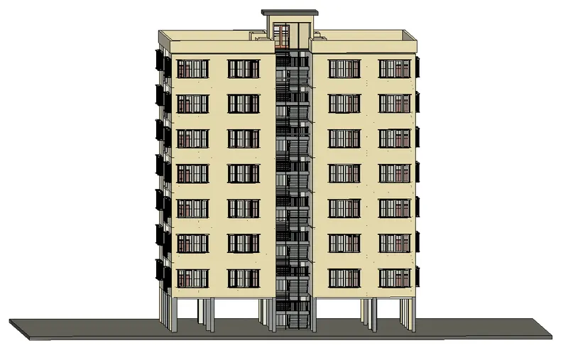
BUILDING VIEWS AFTER COMPLETING ALL THE LEVELS AND TERRACE DESIGN WITH APPROPRIATE MATERIALS AND GLASS FINISHES:
5) Provide a set of drawings in an architectural and structural model to list the following details with categories and appropriate sheet templates included
a. Floor Plans with Annotations
b. Elevations
c. Sections
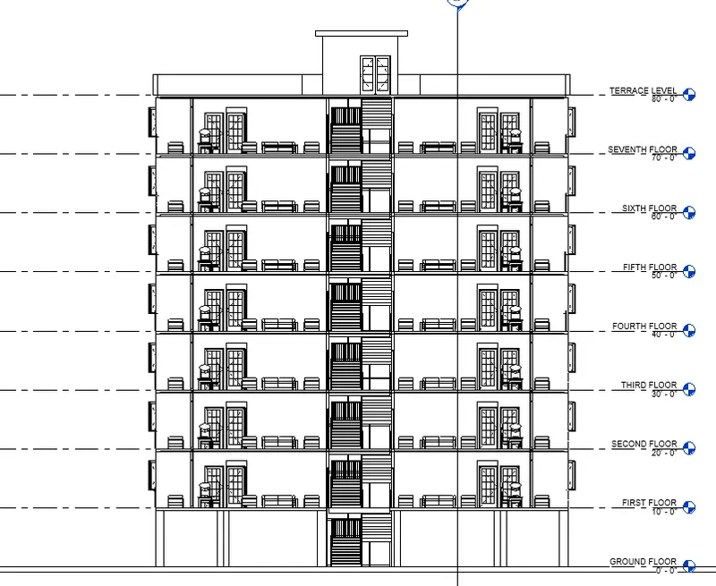
Section A-A
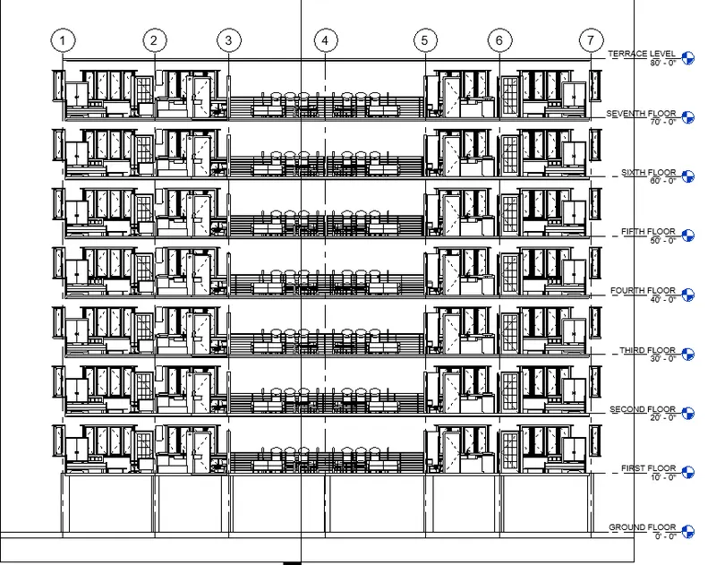
Section B-B
East Elevation
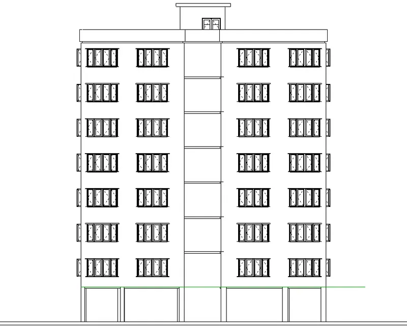
North Elevation
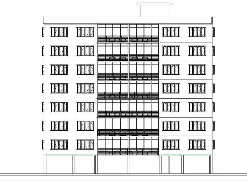
South Elevation
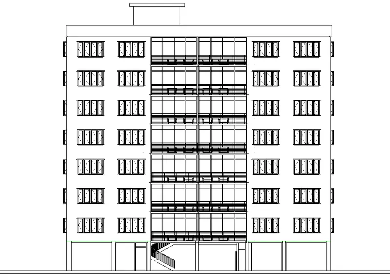
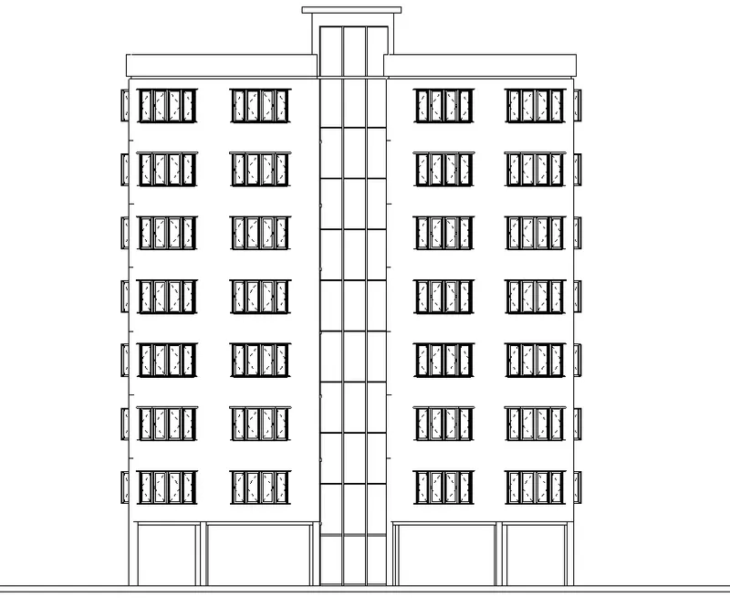
West Elevation
- Put the above views on sheets
- From the view tab, click on the sheet option.
- Select the sheet size and parameters.
- Drag and drop the views you want to incorporate into the sheets.
- Set up the accordant view scales to make things work on the real construction site.
Sheet parameters
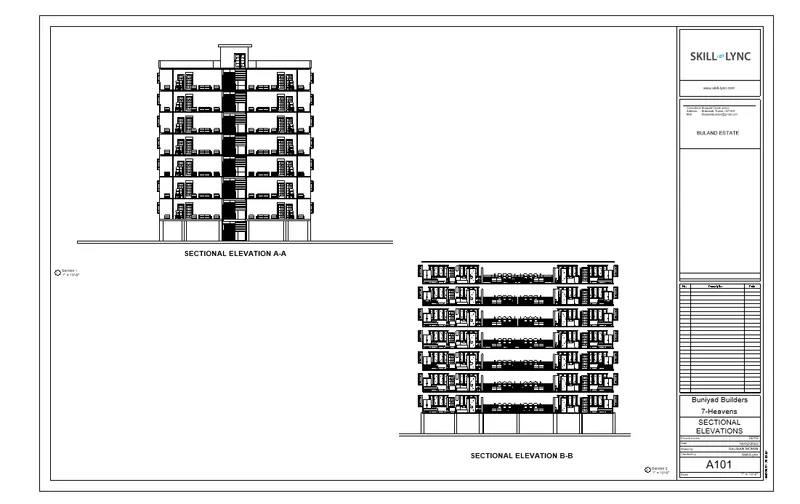
Sheet for building sections
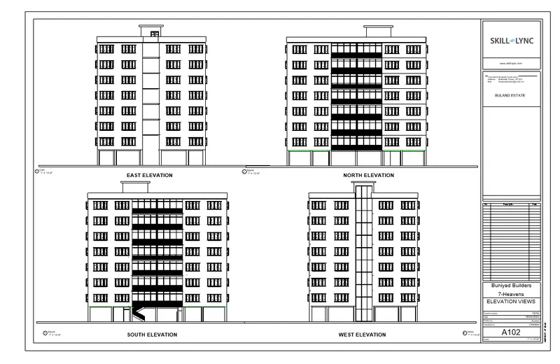
Sheet for building elevations
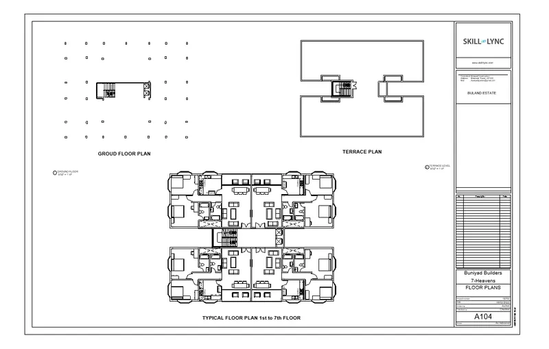
Sheet for floor plans
6) Using the Rendering settings, Render images of the 3D model produced and include the rendered images to the drawing sheets
a. Rendering from interior rooms
b. Rendering from out showing topographic features
c. Rendering through structural framing
- How to create rendered images of your model in Revit
- From the view tab, go to the 3d view dropdown and select the camera.
- Go inside one of your floor plans and set up the camera within a room to create a certain room view.
- Crop or extend the camera view according to the proper visibility.
- Hit "RR" on your keyboard. A rendering settings dialogue box will appear.
- Do the needful settings like image quality, lighting details, sky, background, etc.
- Make sure to place sufficient Architectural lighting while rendering building interiors to avoid loading black images.
- You can load the lights as a family into your project.
- Then, you can put them into place through your ceiling plans.
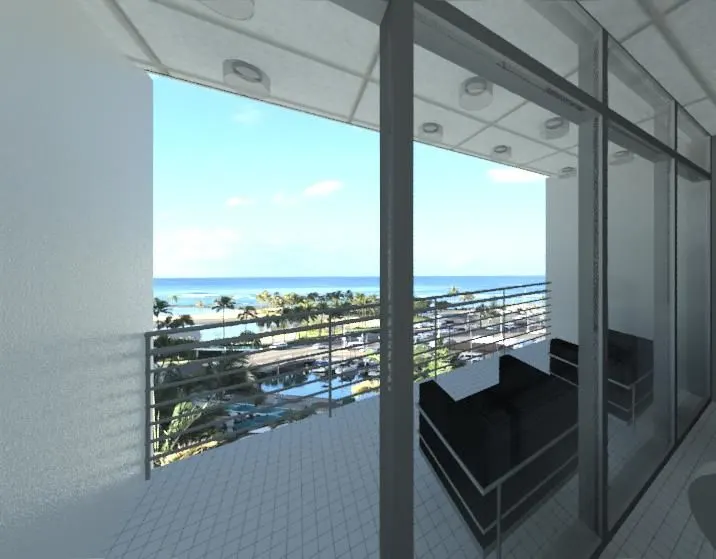
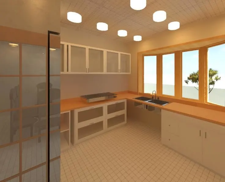
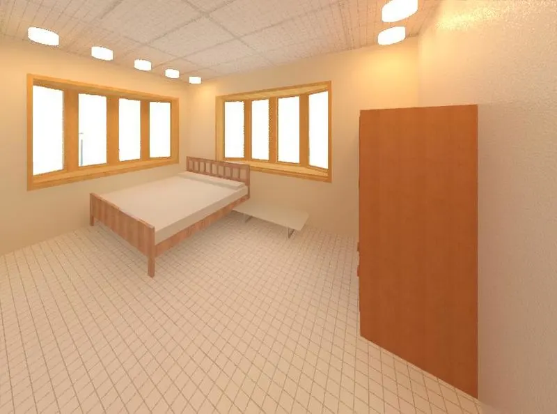
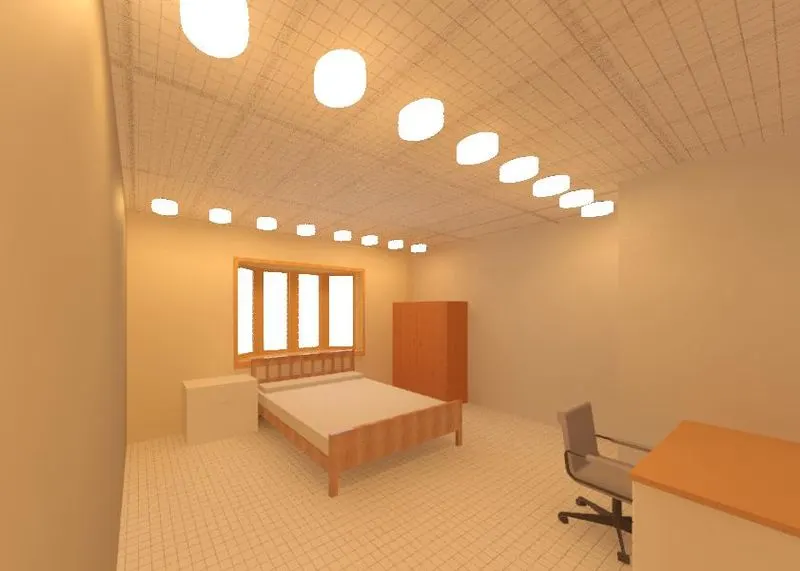
- Different rendered images of our project are inserted below that were created following the procedure mentioned above.
- Interior Rendered Images
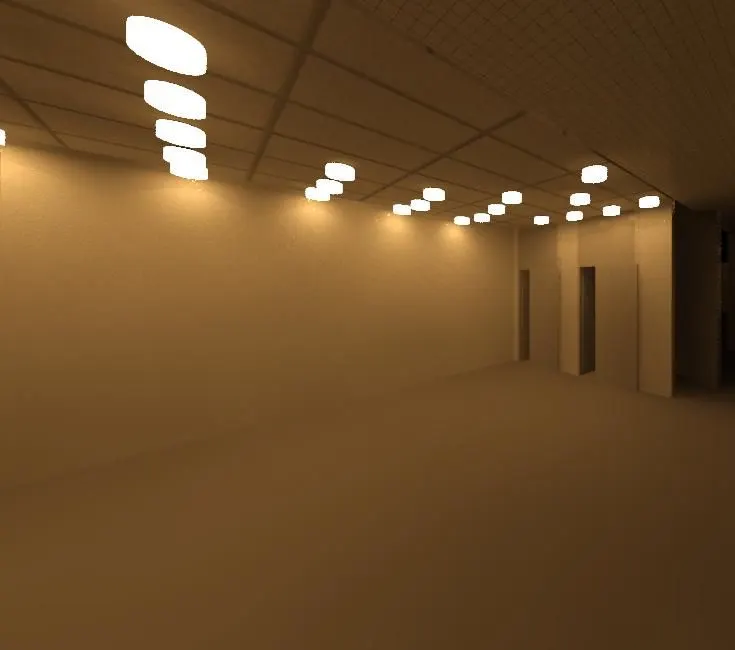
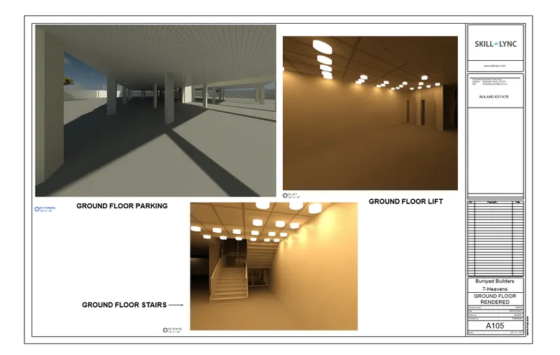
Ground Floor Lift
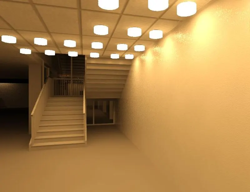
Ground Floor Stairs
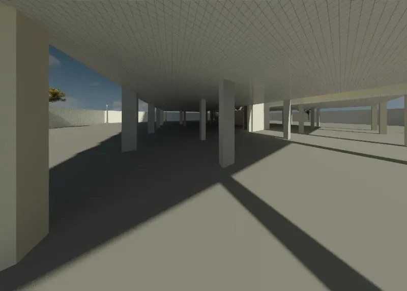
Ground Floor Parking
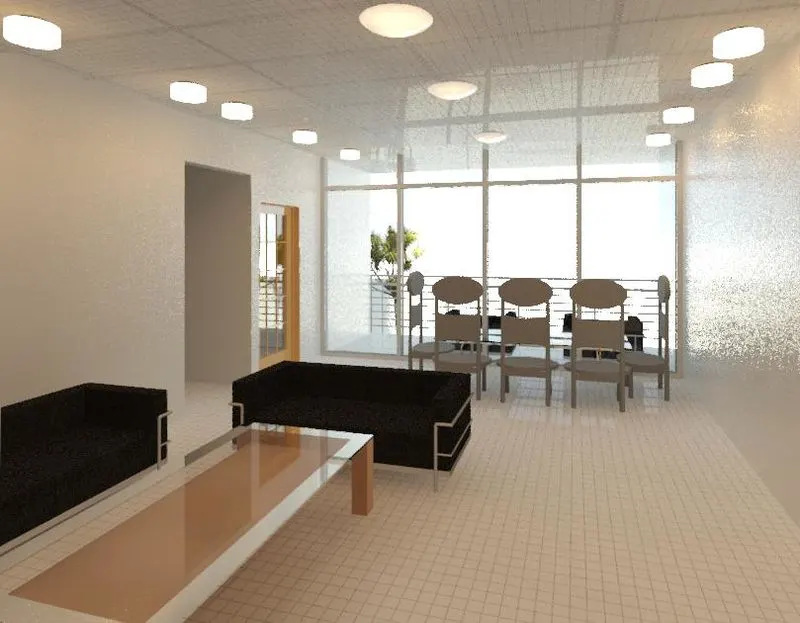
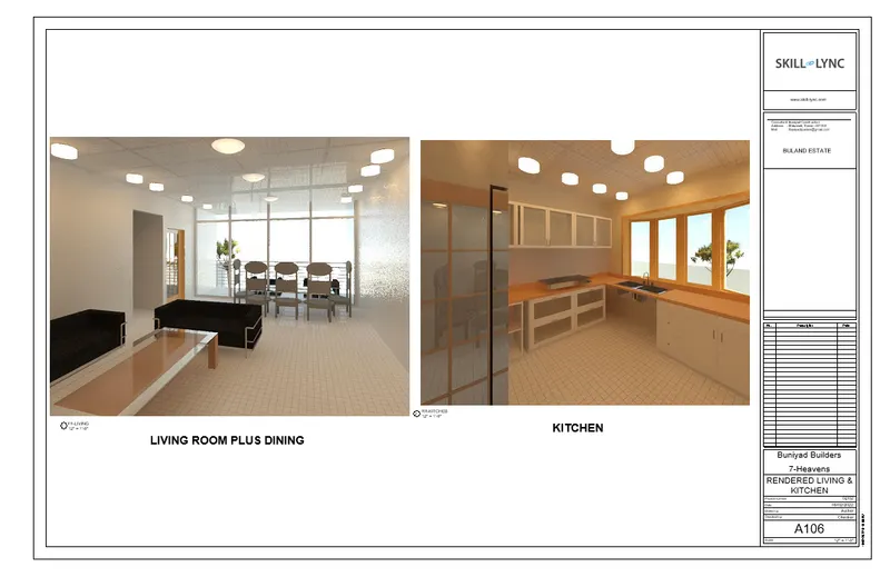
Living Room
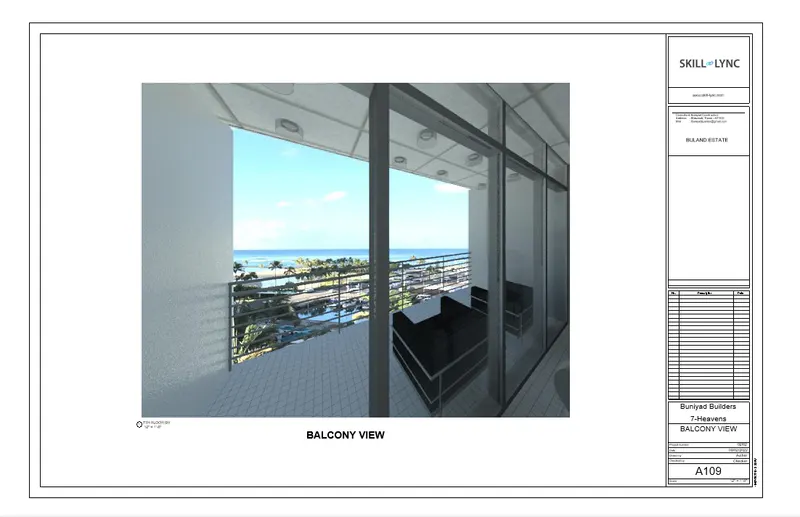
Seventh Floor Balcony View
Kitchen
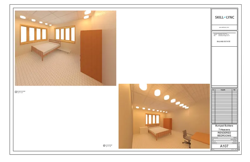
Bedroom
Master Bedroom
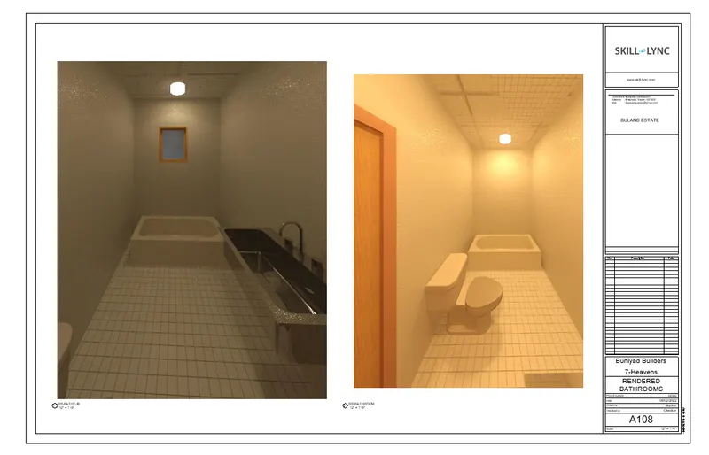
Bathroom
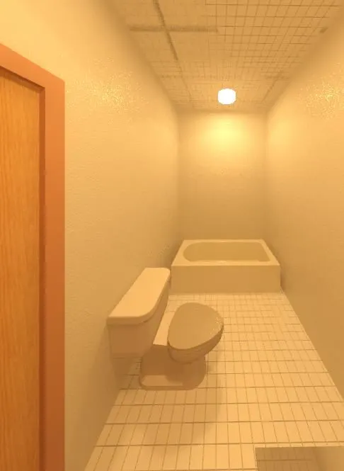
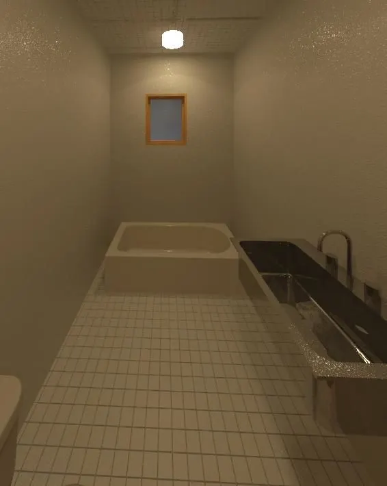
Now that we have created all of the required rendered images relating to our project. We can put them into the sheets and present them to the site in a formal manner.
NOTE: We have used the same sheet parameters as did before for sections and elevations.
Ground Floor Sheet View
Living Room and Kitchen Sheet View
Bedroom Sheet View
Bathroom Sheet View
Balcony Sheet View
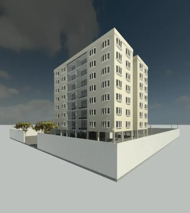
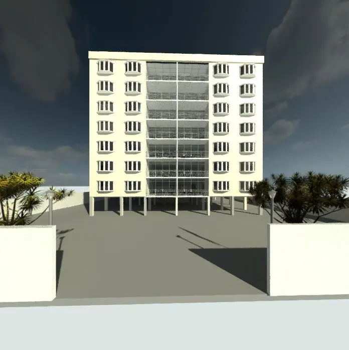
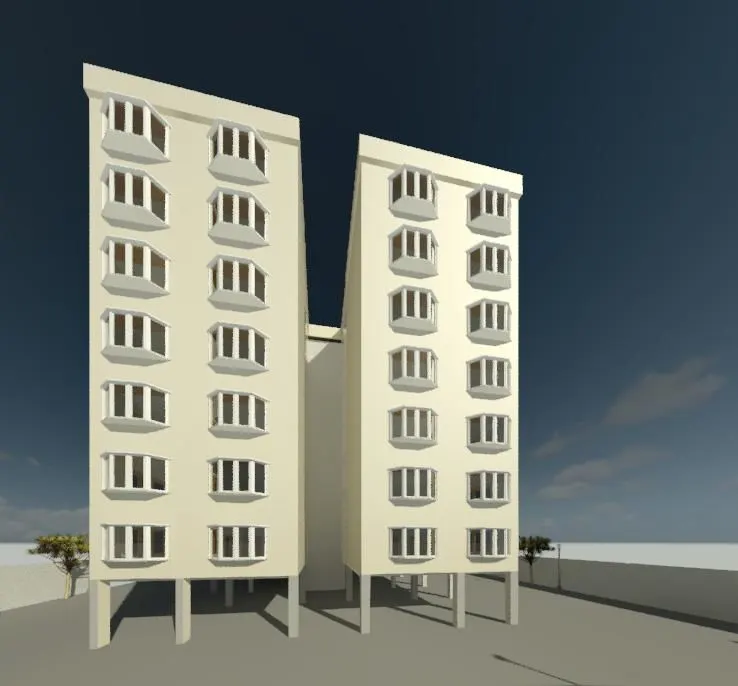
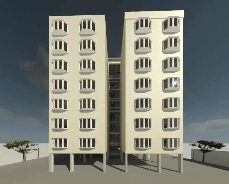
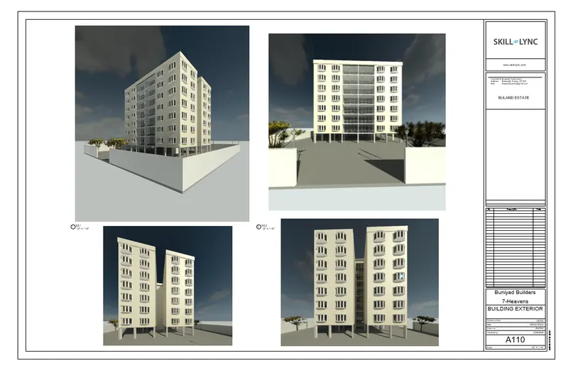
- Exterior Rendered Images
Building Exterior View 1
Building Exterior View 3
Building Exterior View 4
Sheet for Building Exterior Views
7) Print the set of drawing sheets created and submit the drawings from the architecture and structure model.
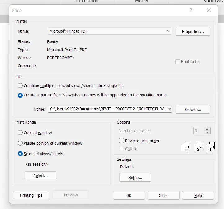
- Procedure to print your drawings in Revit
- Press CTRL+P in your model.
- A dialogue box will appear where you will be asked about what to print.
- you can either specify the window, sheets or views to be printed.
- As we have separated our drawings into different sheets, we go with the sheet print.
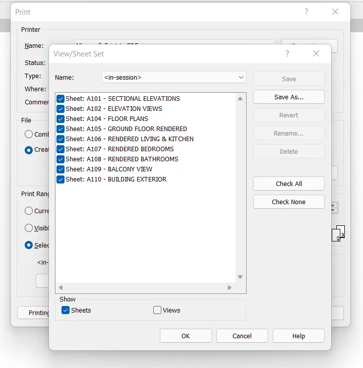
- Then, Revit will ask you to select the sheets you want to print.
- As we want to print every sheet, we will select all.
- Then press Enter then OK. And that was it, all your sheets will be printed if you have a printer attached to your computer.
- Otherwise, all your sheets will be saved as PDF into your system which you can then print from somewhere else where the printer is available.