Creating Architectural and Structural model with 3D rendering using REVIT
1) Select the type of structure you want to build from one of the three below:
a. Multi-Unit Residential Apartment
b. Office Buildings
c. School
ANSWER:-
- The building I want to build is an Office building
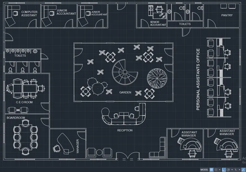
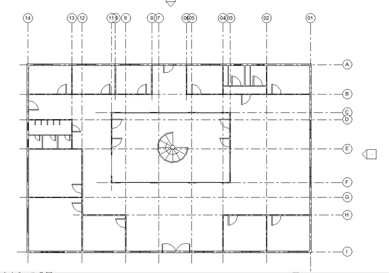
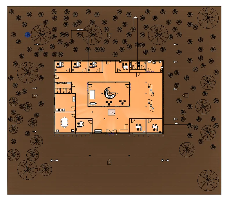
- The below drawing is a plan of the office building I want to build.
2) Assume reasonable assumptions for geographic and location details for your project modeling. Based on assumptions and type of structure selected identify the modeling requirements from NBC
AIM: To identify the modelling requirements from NBC for the selected structure
PROCEDURE:
STEP 1:
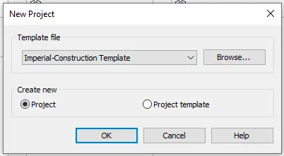
- Open Revit and create a new Imperial-Architectural template and save by appropriate name
STEP 2: Assigning location details
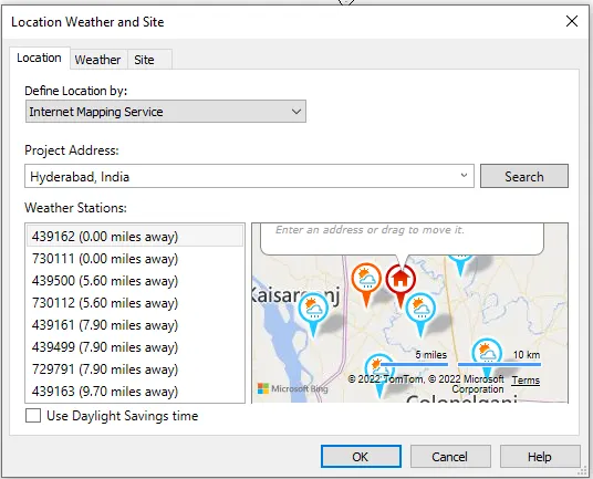
- In manage toolbar select the location tab
- Assign the desired location by search and also select the desired weather station click ok
- Location is set
RESULT: Selected structure Modelling requirements as per NBC
- The selected building is classified as GROUP E - subdivision E1 based upon reference of NBC part - 4 - 3.16
- As per NBC part 4 clause 3.3.1, the building type of construction is type 2 construction
- The building comes under Fire zone no 1
- The open space around the building is not less than 4.5m
- As per NBC the Floor area ratio (FAR) for type 2 construction is taken as 2.9
3) Using the structural model, include the following components based on the type of structure selected
a. Foundation – Isolated / Wall/Matt Foundation
b. Columns
c. Beams Connected to Columns
d. Roof Framing/ Truss
e. Floor / Decks
f. Floor Openings for Elevators and Stairs
AIM: To create foundations; columns, beams connected to columns, roof framing/ truss, floor/ decks, floor openings for elevators and stairs using a structural model template for the structure selected
PROCEDURE:
STEP 1: Creating a structural template
- Open Revit select new and create Imperial-structural template and click ok
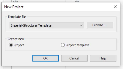
- Save the file in the desired location with an appropriate name
STEP 2: Creating grids
- Open already saved architecture template that assigned location to it in the previous question
- In the insert toolbar select the link cad
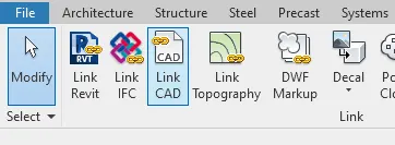
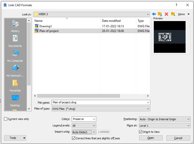
- Select the cad file to link and click ok
- Place the linked cad file at the centre of the elevation views like below
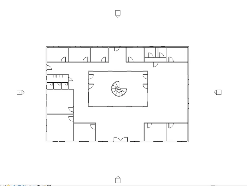
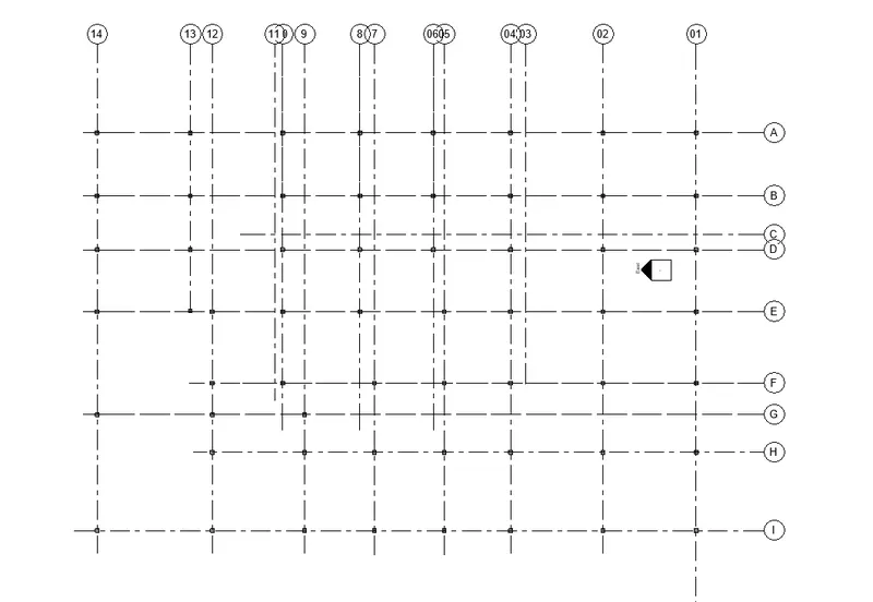
- In the architecture toolbar select grid and assign the grids where ever required
- In collaborate toolbar select collaborate tab and make the architecture template a central file
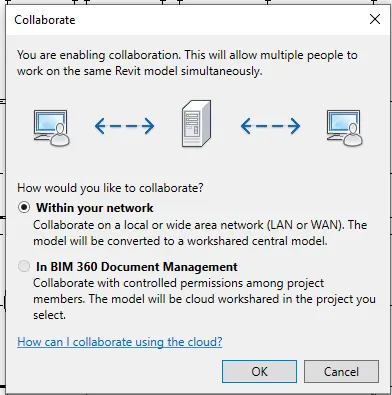
- Save the file after clicking ok then the file is opened for collaborate

STEP 3: Using copy monitor to copy grids in the structural template
- Open the already created structural template file
- In collaborate toolbar select collaborate tab and make the model is ready for collaborate
- Click on ok and save it so that the model is now assigned as a central file
- In insert toolbar select link Revit and add architectural model created along with link cad file also that used in architectural model
- Adjust the cad file and architectural model as appeared in the architectural template and pin the cad link so that it can't move from the assigned coordinates
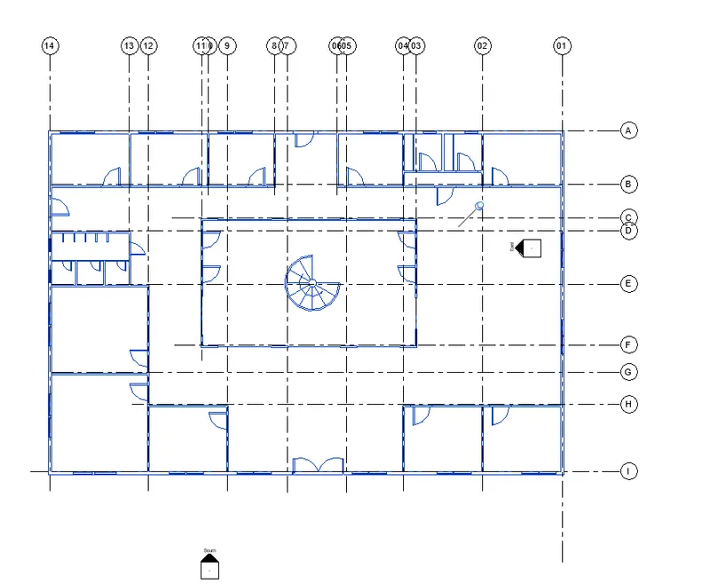
- In collaborate toolbar select the copy monitor tab and carefully select the grids
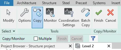
- After selection of grids click finish in copy monitor ribbon above
- To check the grids copied are assigned or not by command VG and unlink the loaded links in Revit links and uncheck the imported cad file
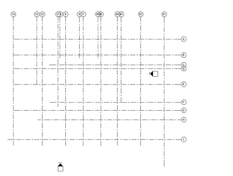
- From the above picture, it is confirmed that the grids assigned using copy monitor are done
STEP 5: Creation of combined template
- Open Revit select a new Imperial - architectural template and save it as Combined model
- In collaborate toolbar select collaborate tab and make the template collaborate
- Click on ok and save it so that the model is now assigned as a central file
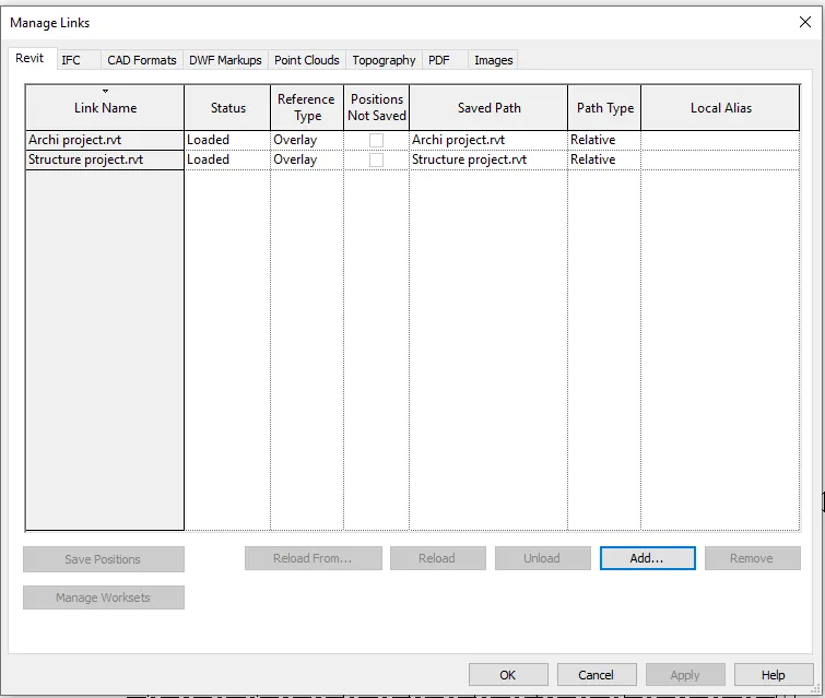
- In manage toolbar select manage links and add architecture model by shared coordinates and click ok
- In manage toolbar select the coordinates tab in dropdown select acquire coordinates and select the architecture link so that the combined model and architecture model share the same coordinates
- Similarly, the same steps have to follow for the addition of the structural model to the combined model
STEP 6: Assign structural elements as mentioned in Question
A) ADDITION OF COLUMNS:
- Open the saved structural model
- Go to the east elevation view assign the levels
- In the structure toolbar select levels and assign desired levels
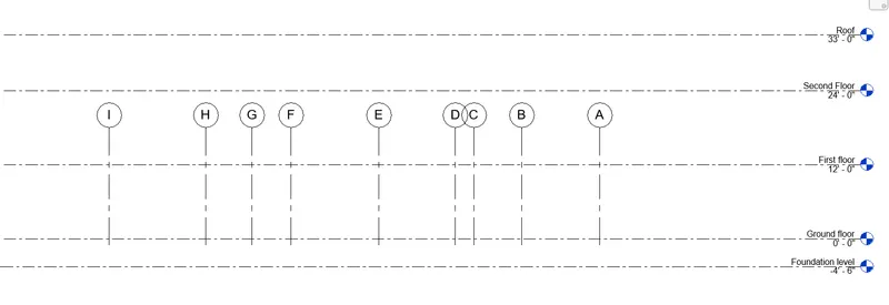
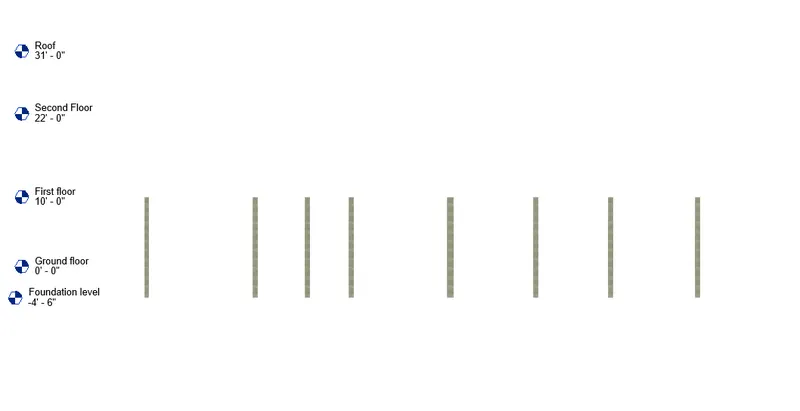
- In the structure toolbar select column and in edit type select the suitable column for the structure, for my model I used a 9" x 9" rectangle column
- The columns are assigned in ground floor plan which is base offset and top offset is the first floor and also assigned to the foundation level
- Select the column at grids and assign the columns
B) ADDITION OF FOUNDATIONS:
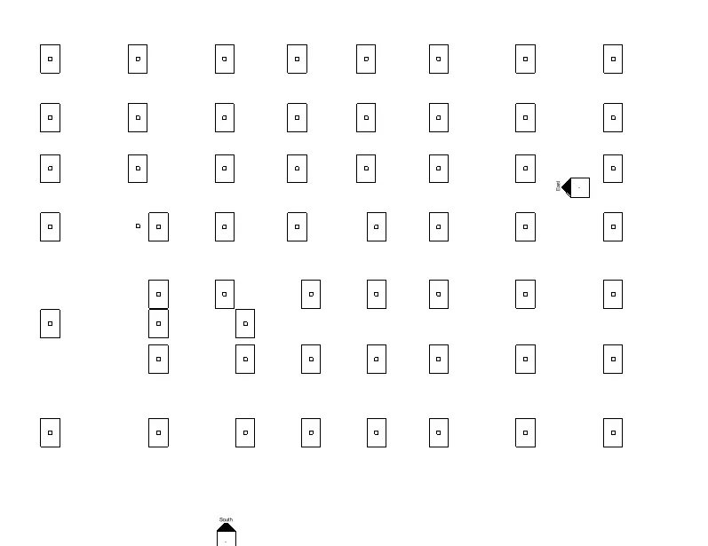
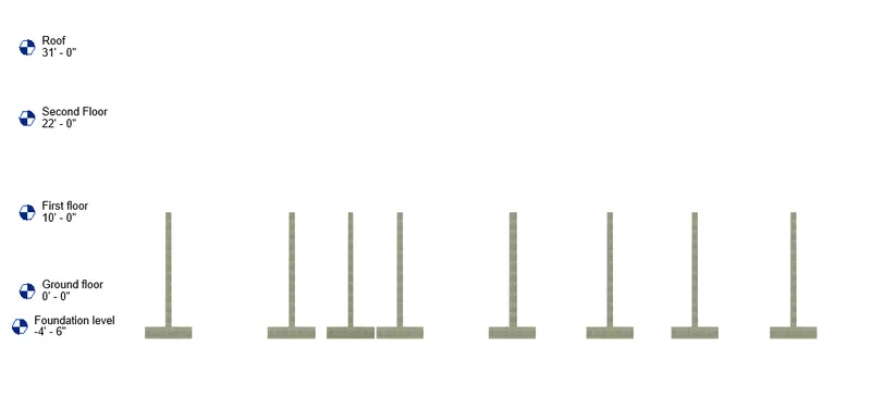
- Go to the foundation level
- In the structure toolbar select isolated footing and assign by at columns option
C) ADDITION OF BEAMS:
- Go to First floor level
- In Structure toolbar select beam and in edit types assign required dimensions as per structure requirement
- Assign in first floor level
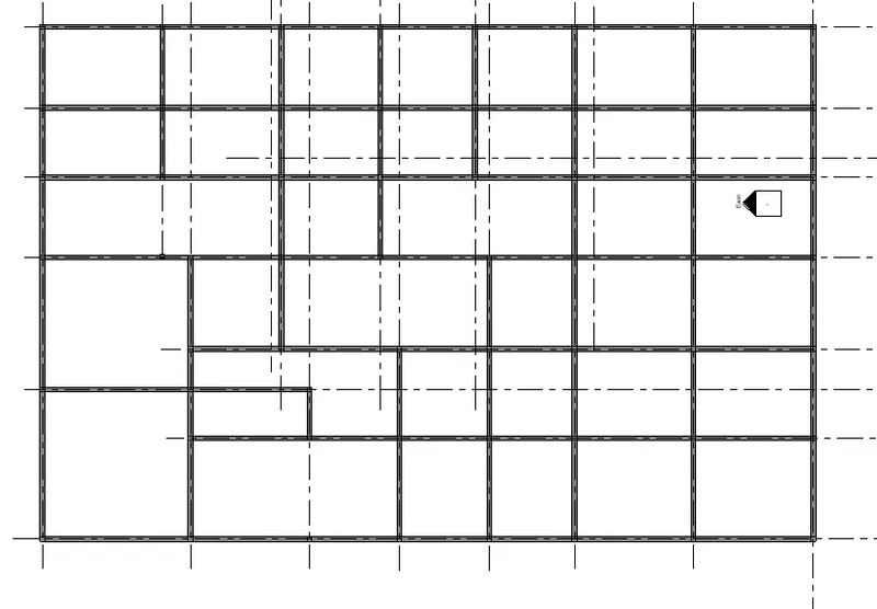
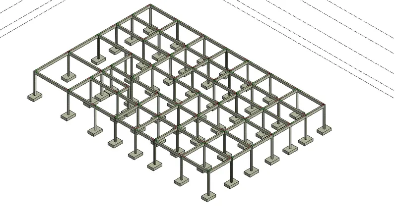
D) ADDITION OF FLOOR:
- Go to ground floor level
- In the structure toolbar select floor tab and in the dropdown select structural floor and assign the floor with the help of boundary lines by the midpoint of columns
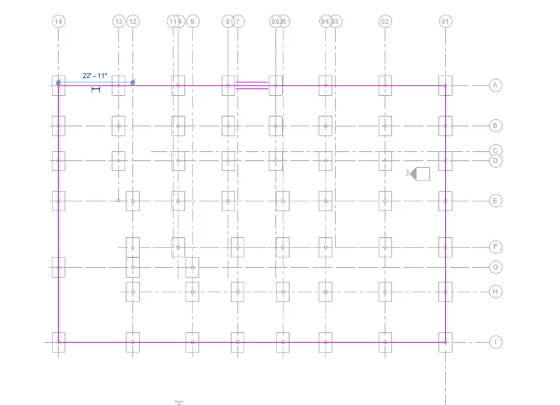
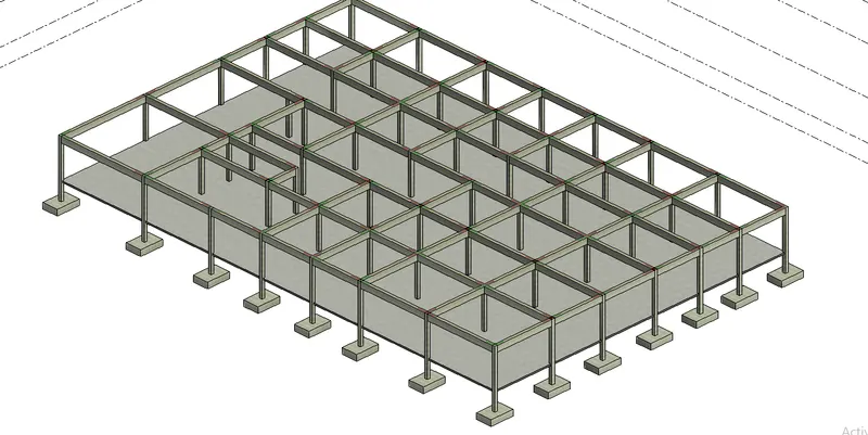
E) Assigning the created columns, beams and floor to the levels
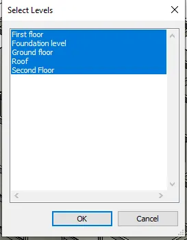
- Select all in 3D view and filter the elements that are required
- With the help of copy and paste, tabs assign the elements to the levels
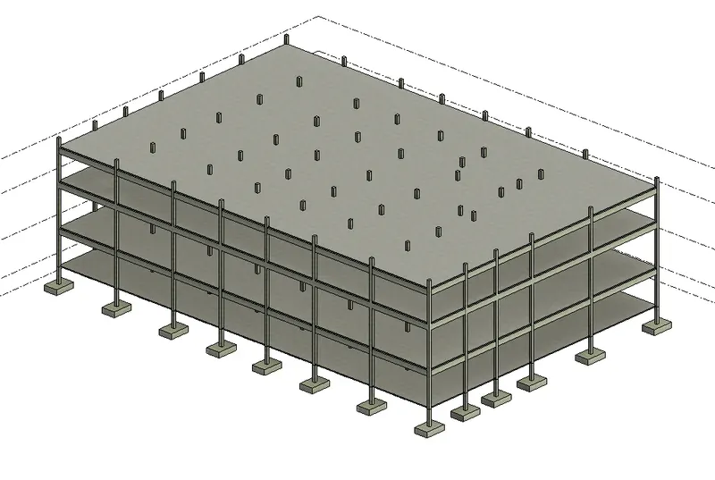
RESULT:
- 3d View of the structural model after adding all required elements
4) Using the architectural model, include the following components based on the type of structure selected
a. Wall Layout with appropriate material and finishing
b. Exterior façade with fancy finish
c. Interior partition walls to size rooms
d. Components to add details to a room ( Desk, Chair, Lighting, Plumbing fixtures)
e. Add components such as stairs Elevators
f. Have at-least one side of the building with curtain walls and glass panels
g. Include interior and exterior lighting fixtures
h. Place proper topographic components from outside ( Trees, Parking, Plants) to add details to the model
AIM: To Create architectural components based on the type of structure selected
PROCEDURE:
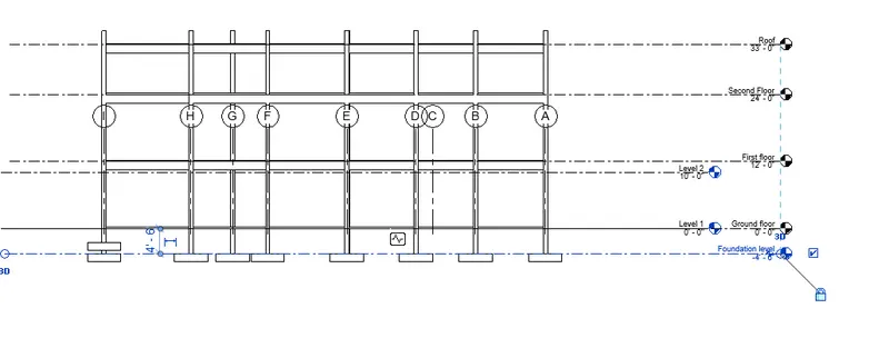
STEP 1: Open of structural file and assign levels by copy/monitor
- Open architectural template that has already been created
- After opening the architectural file close the structural file if opened in other tabs
- In manage toolbar select the manage links and add the structure file
- In collaborate toolbar select the copy monitor option and in the dropdown select the select link and select the linked Revit file
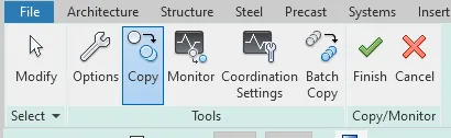
- Copy all the levels required and click on the finish
- After selection of the levels, we can check that assigned levels are copied or not by command VG, go to Revit links select custom and in Annotation categories select custom and uncheck levels click apply and ok the assigned levels by using copy/ monitor is done
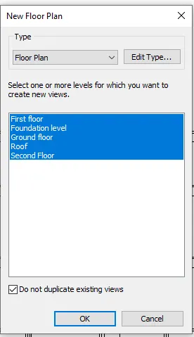
- After c creation of levels, create floor plans
- In view toolbar select plans in the dropdown select floor plans that are required and click ok
STEP 2: ADDITION OF WALLS
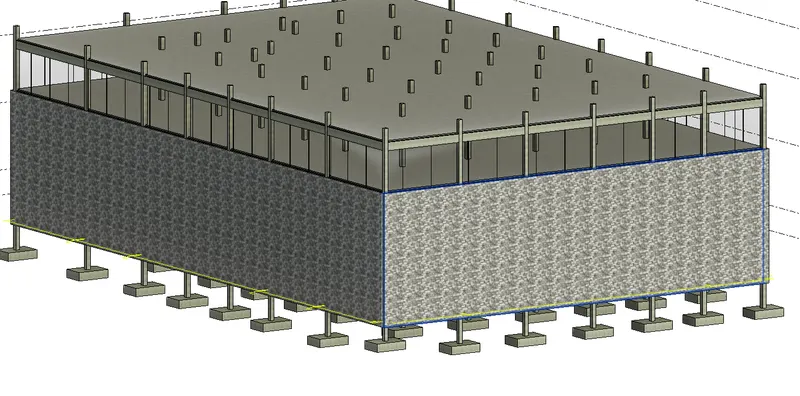
In the architectural toolbar select the wall
Select the desired or required wall dimensions using edit types
The type of walls used in this project are
- Generic - 9"
- Interior - 4 7/8" partition wall
- Curtain wall -exterior glazing
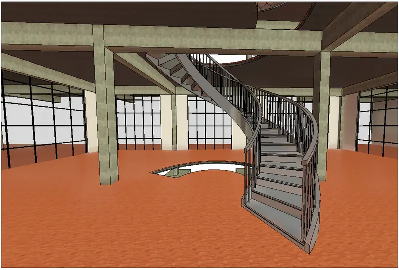
STEP 3: Addition of staircase, partition walls and exterior facade
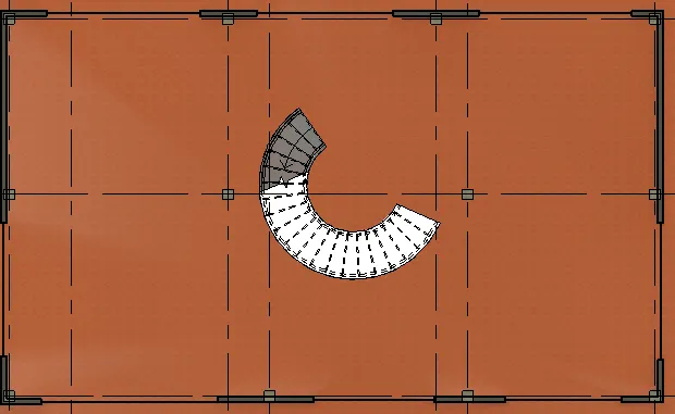
- In architecture, toolbar select stair and assign as per structure requirement
- With the help of shat open the floor is directed for space to the stairs
Partition walls:
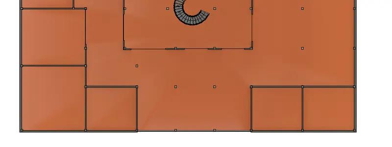
- In architecture toolbar select wall and in properties browser edit to the partition wall size
- Assign the portion wall as per structure requirement
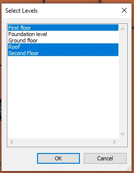
- select the created partition walls and copy and paste to aligned floors as desired
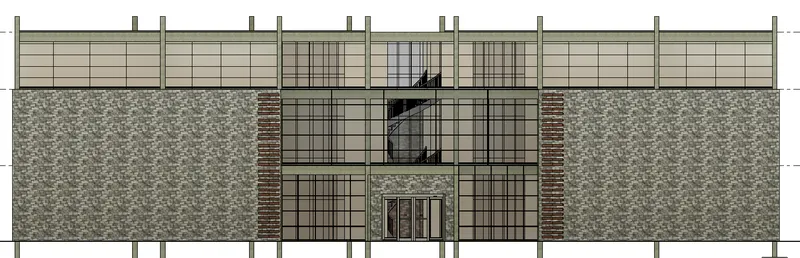
Exterior Facade:
STEP 4: Adding Door, windows, ventilators and components to the model
ADDING OF DOORS:
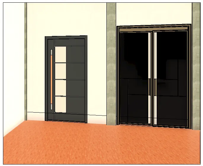
- In the architectural toolbar select the door option and assign the doors as per the structure requirements
ADDING OF WINDOWS:
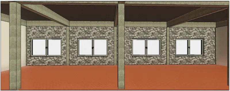
- In the architectural toolbar select the window option and assign the windows as per the structure requirements
ADDITION OF COMPONENTS:
- In the insert toolbar select the load families to load the desired families as required for the model
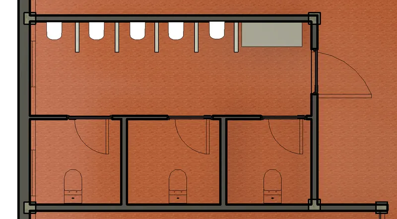
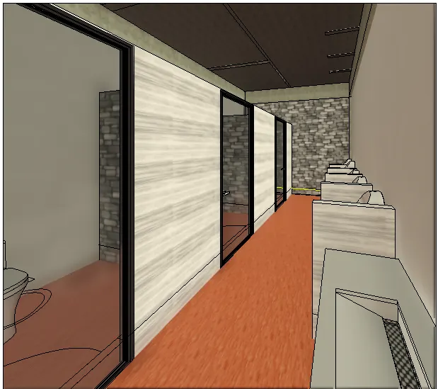
- WASHROOM
- PANTRY
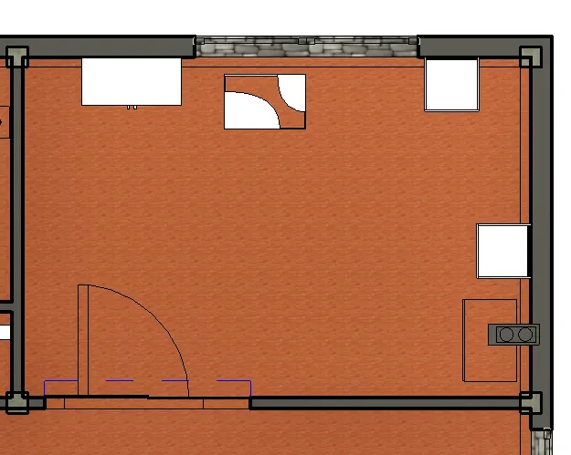
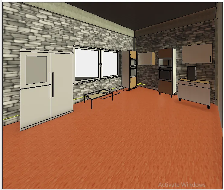
- OFFICE ROOMS:
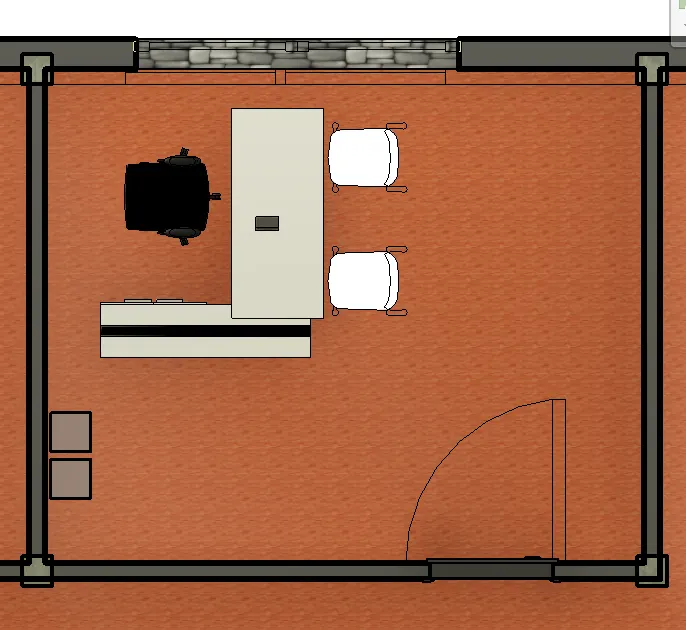
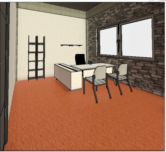
- RECEPTION
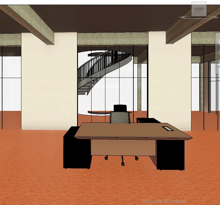
STEP 5: Ceiling, interior & exterior lighting fixtures and ROOF
Ceiling and interior light fixtures
- In the Architectural toolbar select the ceiling and assign it to the model in plan views
- In Insert toolbar select load families and load the required light fixtures
- Go to ceiling view and assign the interior lights wherever required
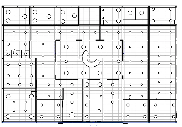
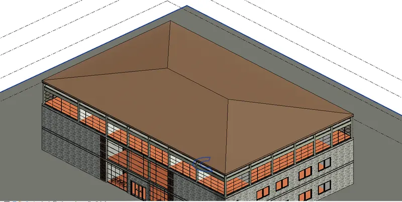
Assigning roof:
- In architectural toolbar select the roof and assign it in roof level with the help of boundary and in properties browser, edit types assign dimensions and type of material
ADDITION OF EXTERIOR LIGHTING:
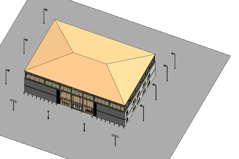
STEP 6: Addition of topography and components related to it
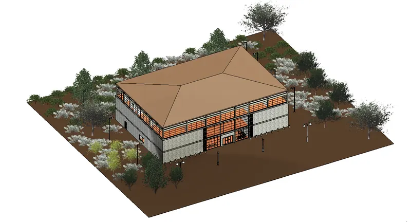
RESULT:
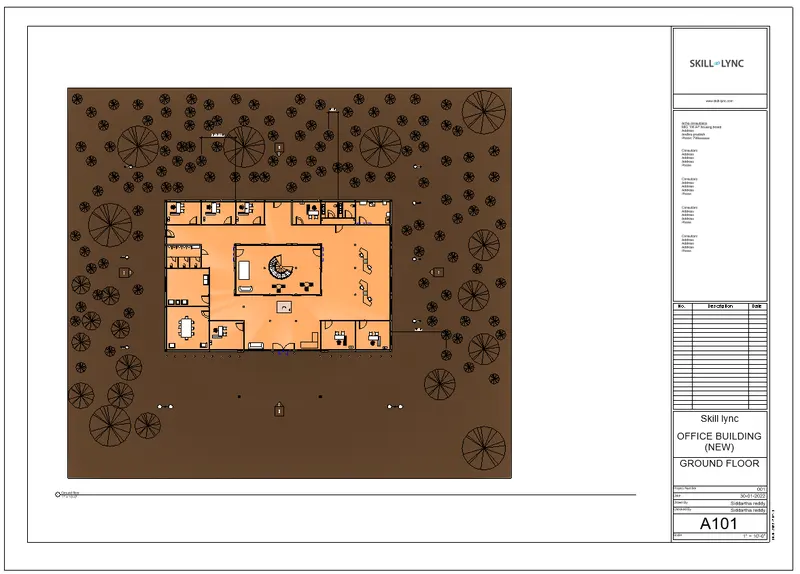
Final drawing of ground floor pan after adding all components to the model
5) Provide a set of drawings in an architectural and structural model to list the following details with categories and appropriate sheet templates included
a. Floor Plans with Annotations
b. Elevations
c. Sections
AIM: To provide a set of drawings from architectural and structural drawings into the sheet template
PROCEDURE:
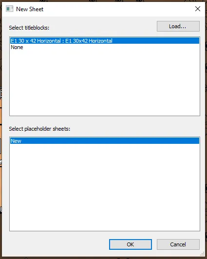
STEP 1: Creation of sheet
- In view toolbar select the sheets in pop up window select the required sheet
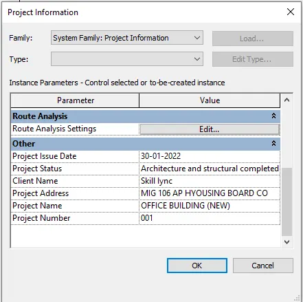
STEP 2: Assigning project information
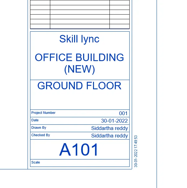
- In manage toolbar select project information and assign the dedtails
STEP 3: Details of the project
- By double clicking on the logo or any editable content opens in new tab there we can edit as per requirements
- Assigning address, sheet numbers and other details
RESULT:
A) FLOOR PLAN;
- Ground floor plan
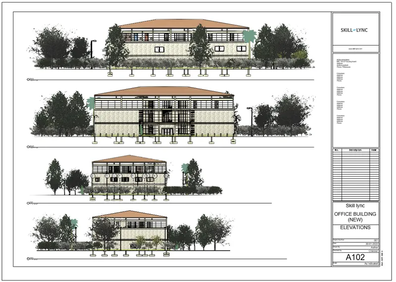
B) Elevations:
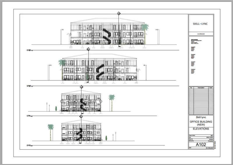
Providing all the elevations in one sheet
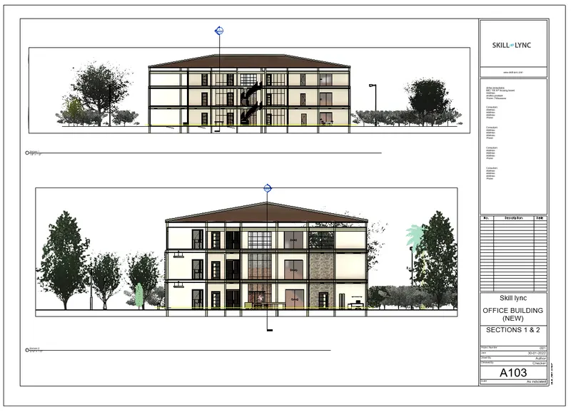
c) SECTIONS:
Longitudinal and Transverse sections in one sheet
6) Using the Rendering settings, Render images of the 3D model produced and include the rendered images to the drawing sheets
a. Rendering from interior rooms
b. Rendering from out showing topographic features
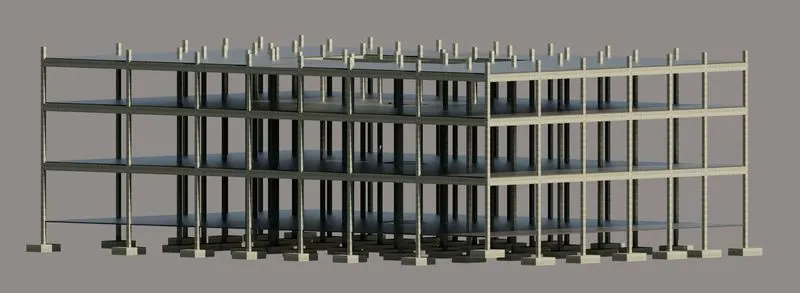
c. Rendering through structural framing
AIM: To use render settings to render the interior rooms, 3d model with topographic features and structural framing
PROCEDURE:
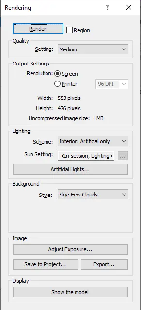
RENDER BY WORKSTATION SETTINGS
- In view toolbar select the render option and assign the desired settings
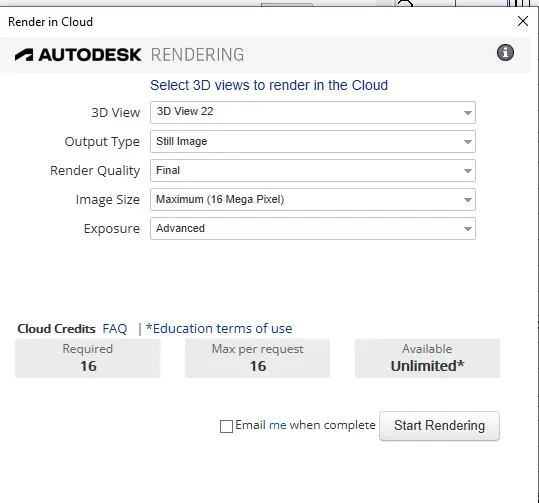
RENDER SETTINGS FOR CLOUD RENDERING:
- In view toolbar select the cloud render option and assign the desired values
A) Rendering from interior rooms:
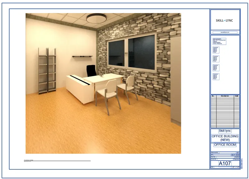
- office room
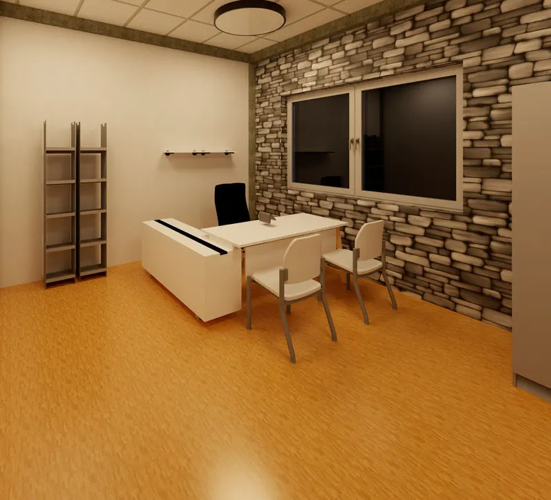
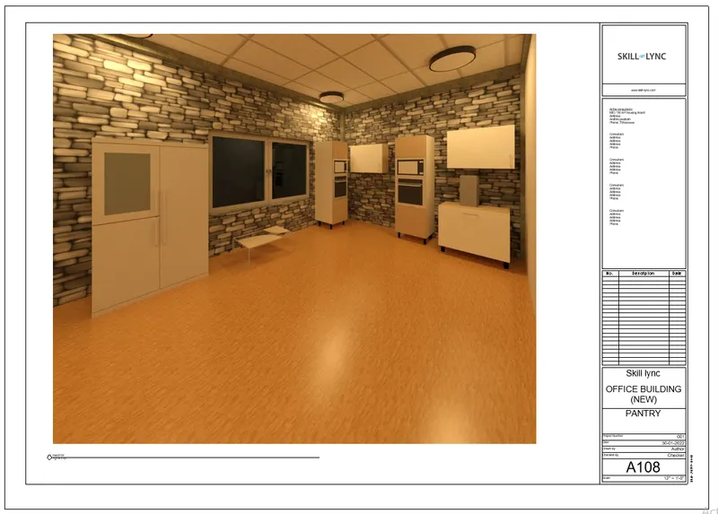
- PANTRY
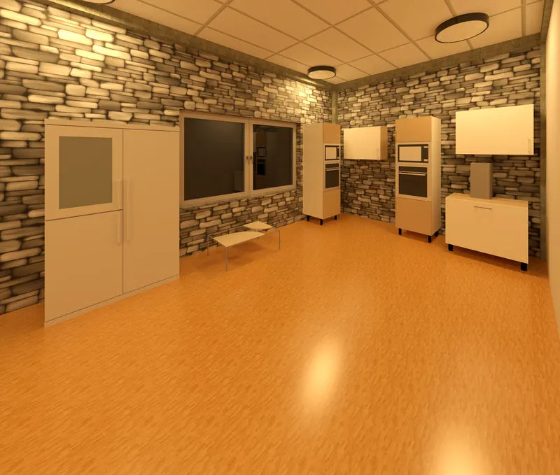
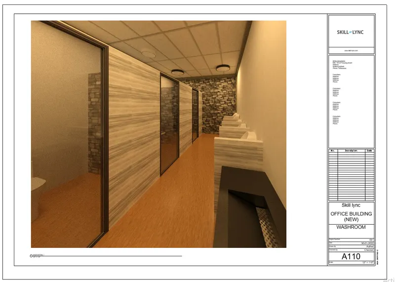
- WASHROOM
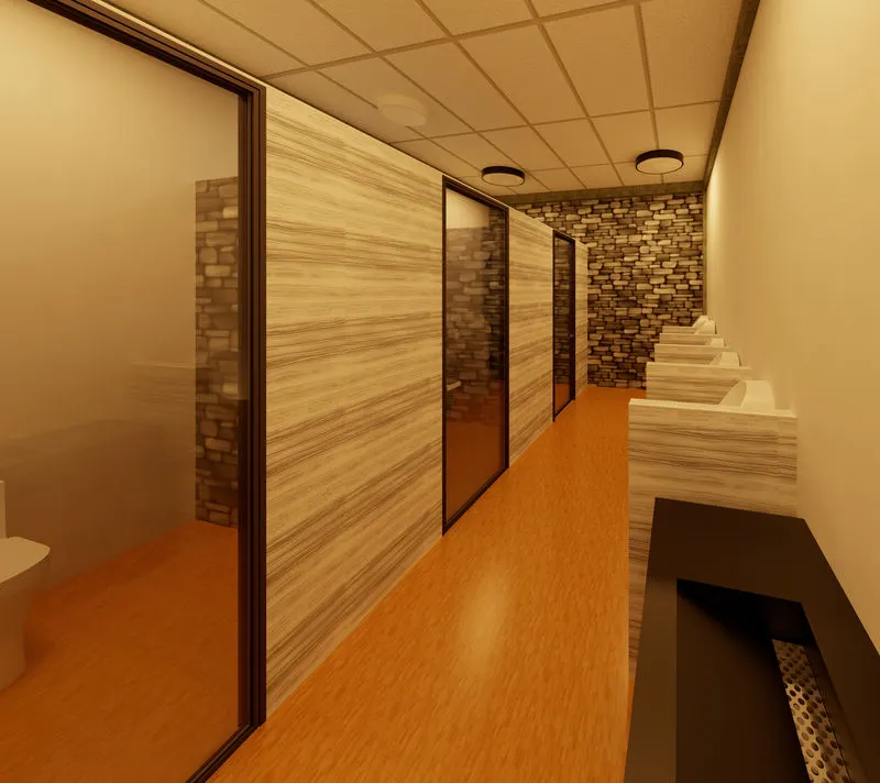
- RECEPTION
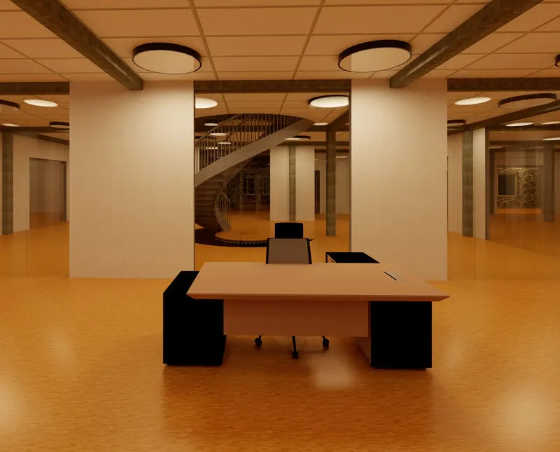
- STAIRWAY
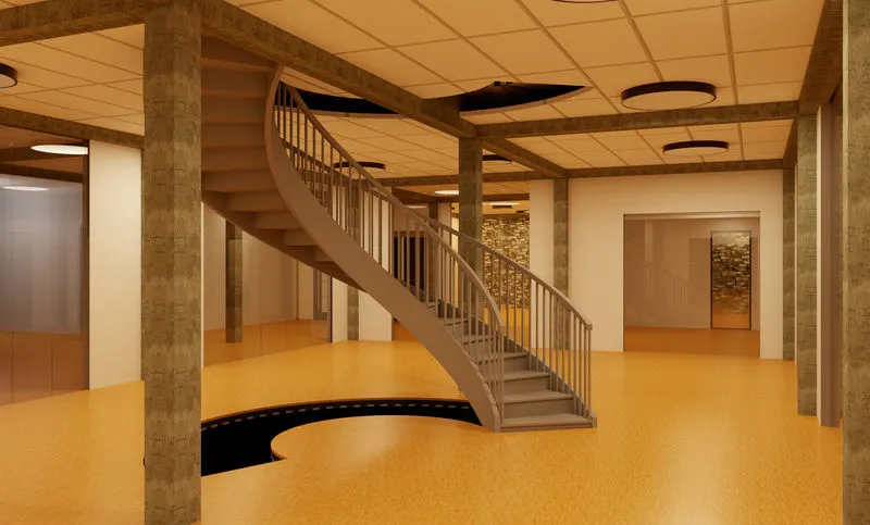
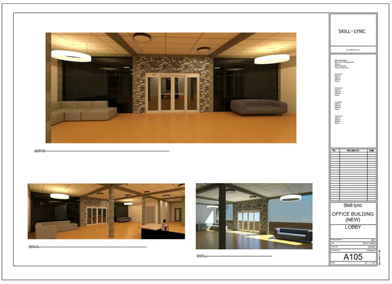
- LOBBY
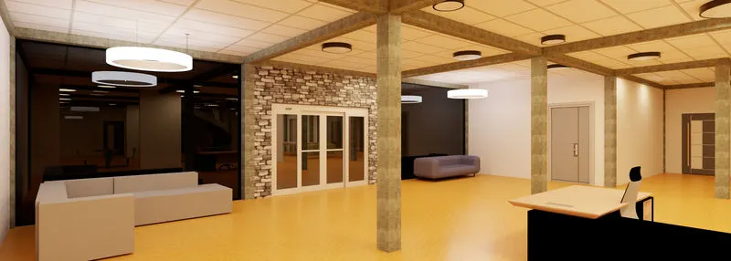
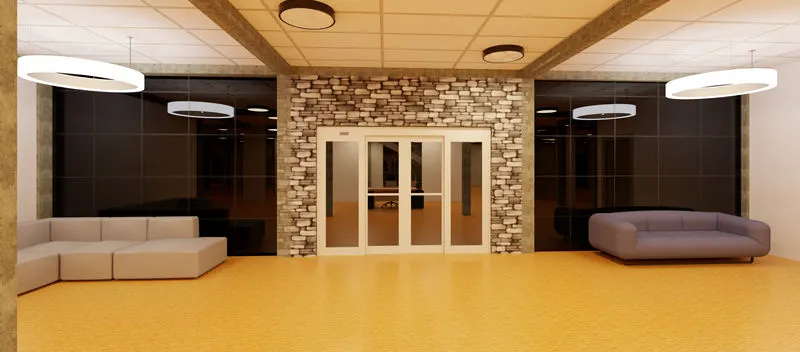
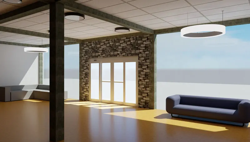
B) Rendering from out showing topographic features:
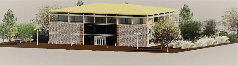
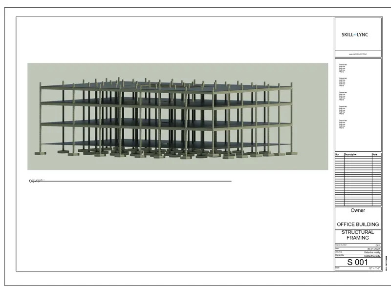
C) Rendering through structural framing:
RESULT:
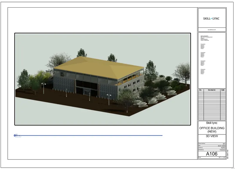
Sheets are created for rendered images
A) 3D VIEW
B) FRONT VIEW:

C) OFFICE ROOM:
D) LOBBY:
E) PANTRY:
F) WASH ROOM :
G) STRUCTURAL FRAMING:
7) Print the set of drawing sheets created and submit the drawings from the architecture and structure model
AIM: To print the set of drawing sheets created and submit the drawings
PROCEDURE:
- Click CTRL+P in keyboard, pop up window regarding print data will appears
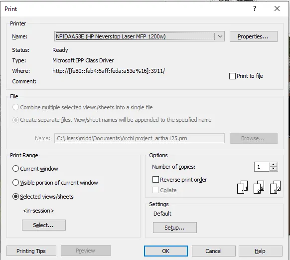
- Click on select views/ sheets
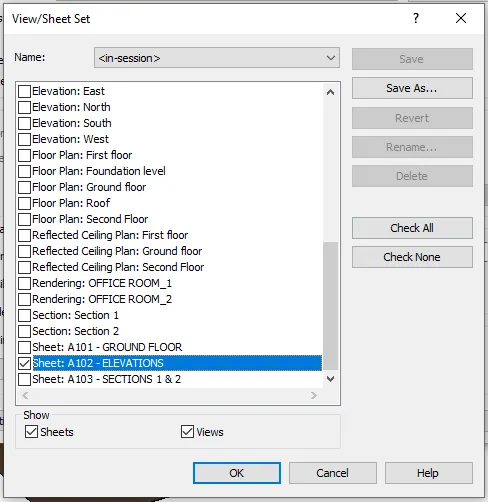
- Select the desired view/ sheet want to print
RESULT: