Creating Architectural and Structural model with 3D rendering using REVIT
Name: Allan Bryan Jayson Cruz
Course: Master’s Certification Program in High-Rise Building Design & Analysis
Date: January 30, 2022
Challenge 7_Creating Architectural and Structural model with 3D rendering using REVIT
********************************************************
1 Aim & Introduction
***************
Aim
This challenge aims to set the student in a learning environment where practical application of the basic learnings of Revit Software modeling is applied.
Introduction
Revit is a building information modelling software that allows the user to create and design a 3D model building structure. It is an architectural, structural, and mechanical software where the user can provide 3D illustration of the building as well as its design.
********************************************************
2 Detail Procedure
***************
1) Select the type of structure you want to build from one of the three below:
- Multi-Unit Residential Apartment
- Office Buildings
- School
For this Project, I select a Multi-Unit Residential Apartment Building. The Project will contain Architectural and Structural models appropriate to the structure.
***************
2) Assume reasonable assumptions for geographic and location details for your project modeling. Based on assumptions and type of structure selected identify the modeling requirements from NBC
General Information and Requirements of the Residential Building are as follows:
- Type of Residential Building : Detached building
- Minimum Plot Size : More than 250m2
- Frontage : above 12m
- Projected Height of the Building : Less than 10m
- Rear Open Spaces : 3m
- Side Open Spaces : 3m
- Occupancy Classification : Residential
- Type of Construction : Type 1
- Projected Height of the Building = 10m
- Fire Zone = Zone No. 1
- Location = Tokyo Japan
Note: All parameters are assumed with respect to NBC to NBC.
***************
3) Using the structural model, include the following components based on the type of structure selected
***************
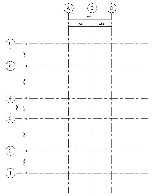
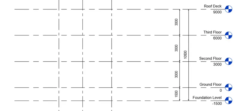
The following elements will be modeled under the Structural Template. The grids and levels are already layed out as below. To create the grids and the levels, the Grid and Level tool under Architecture tab/Structure tab --> Datum is used.
Grids, columns, foundations, and beams may be adjusted to accomodate spacing requirements.
GRIDS:
LEVELS:
a. Foundation – Isolated / Wall/Matt Foundation
PROCEDURE:
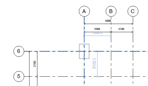
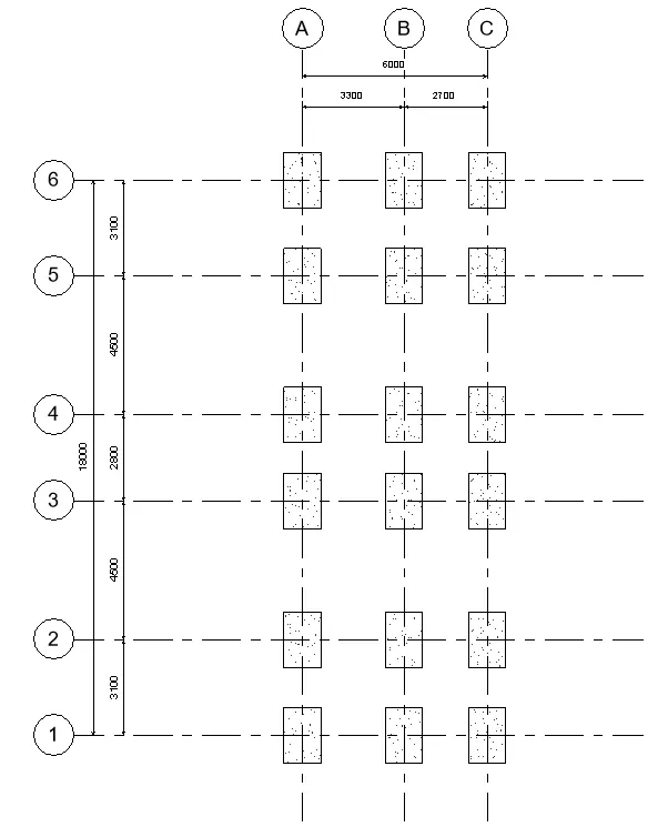
- The foundation is added on the foundation level.
- To add the foundations, go to Structure tab --> Isolated
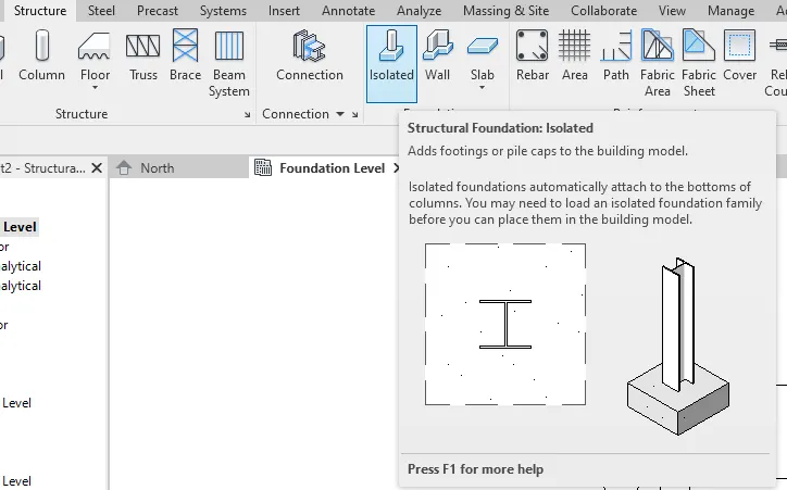
- Add the isolated foundation on the Grid Lines. You can adjust the locations of the foundations once the columns are modeled.
***************
b. Columns
PROCEDURE:
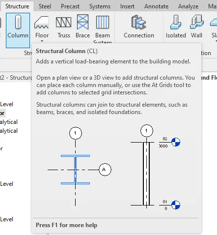
- Now to add the columns, set it on the ground level. Under the structure tab, select the column tool.
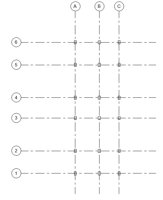
- Edit the column instances in the properties tab to make sure that the columns will be modeled until the roof level. Check the 3D view to see whether it is modeled correctly.
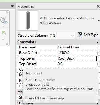
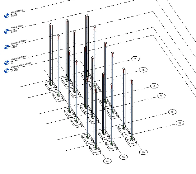
- You can position the columns accordingly.
***************
c. Beams Connected to Columns
PROCEDURE:
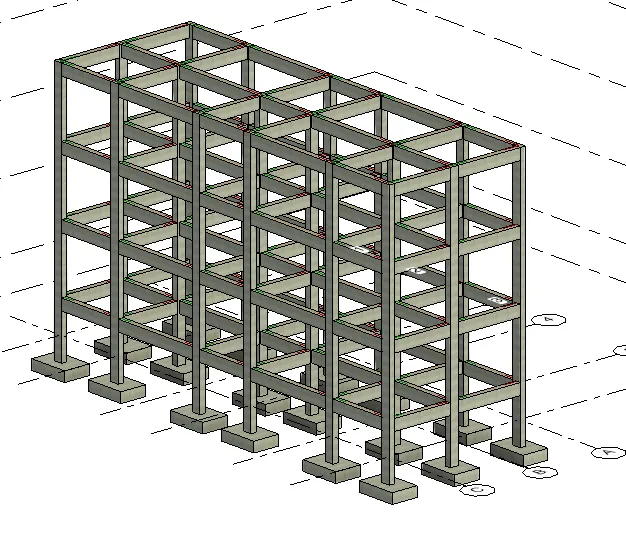
- Connect the columns using beams at all levels. Select beam tool under the structure tab.
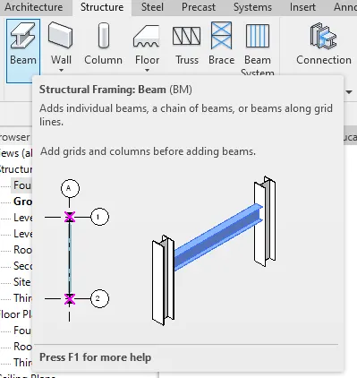
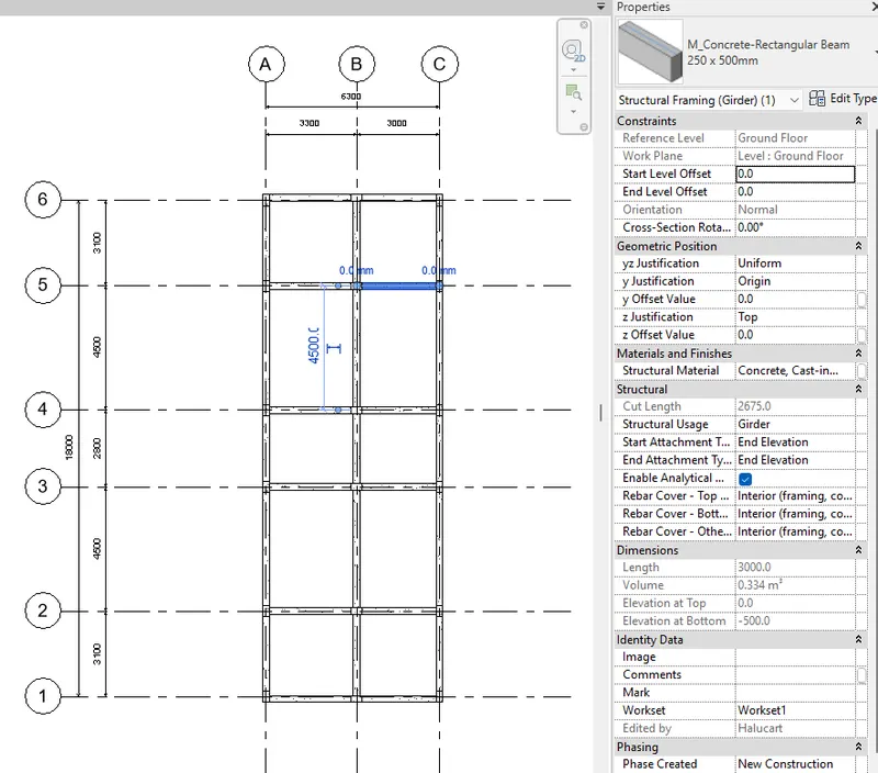
- Do the same for all levels and check on the 3D view.
***************
d. Roof Framing/ Truss
PROCEDURE:
- Since Roof deck will be used, roof framing or truss will not be applicable in the structure. Proceed to floors and decks.
***************
e. Floor / Decks
PROCEDURE:
- To add the floors and decks, go to structure tab and select the Floor tool.
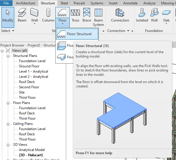
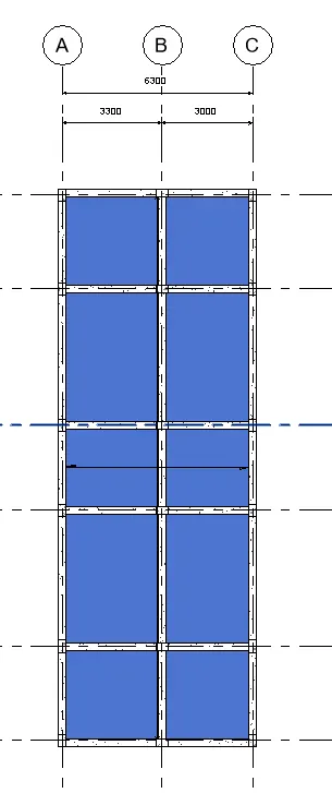
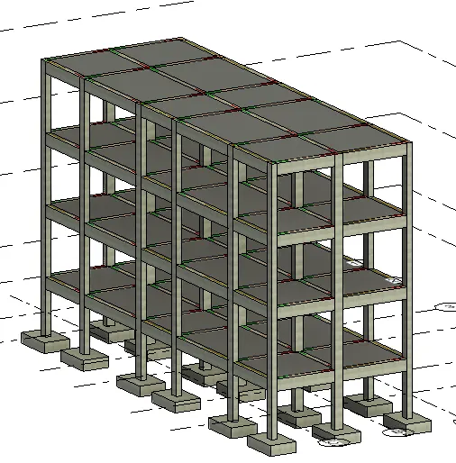
- Add floors to all levels.
***************
f. Floor Openings for Elevators and Stairs
PROCEDURE:
- To add the openings for the stair, edit the slab boundary for second floor to roof deck and delete the boundary.
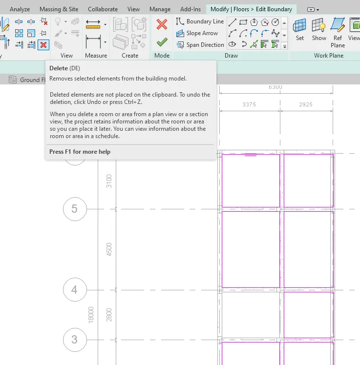
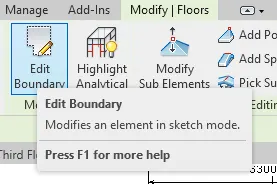
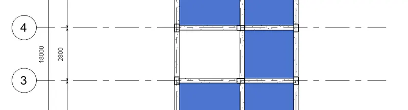
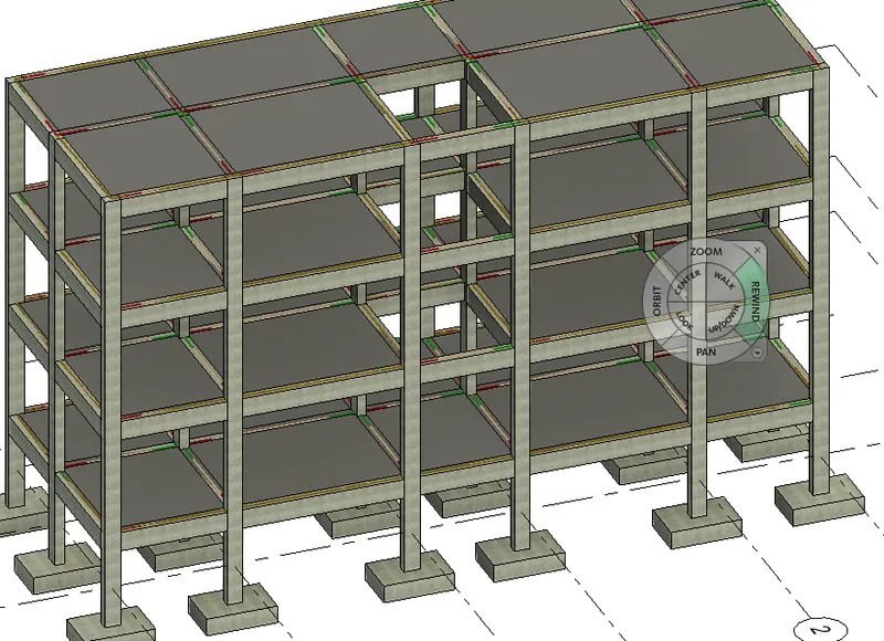
- You can see the opening on the 3D view.
- When finished, align the revised grid lines from the structural model to the architectural model.
***************
4) Using the architectural model, include the following components based on the type of structure selected
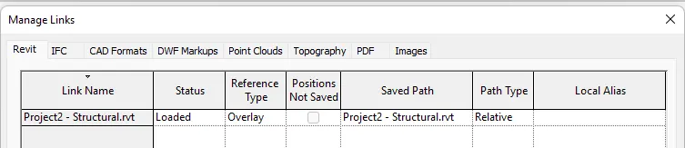
In the architectural model, link the structural model to see the created columns, beams, and foundations to use as boundaries for the architectural elements.
***************
a. Wall Layout with appropriate material and finishing
PROCEDURE:
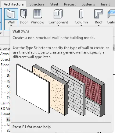
- To add the wall elements, use the wall tool under the Architecture tab.
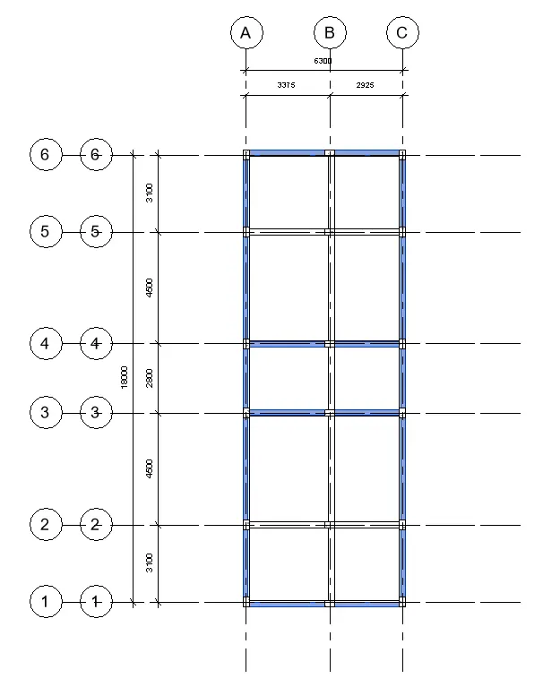
- Create the walls for all the levels. Use the 3D view to check.
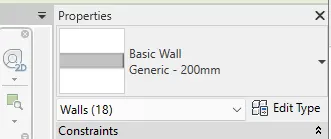
- For the boundary walls, a wall 200mm thick is used.
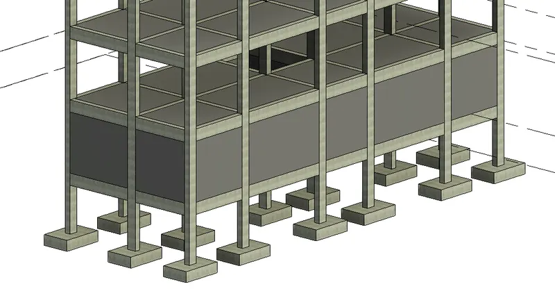
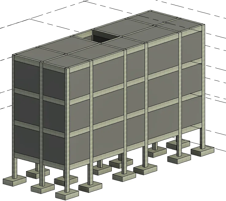
- Create the border walls as needed. Adjust the structural model later after finishing the architectural layout. Keep in mind the structural stability of the building while creating the architectural concept.
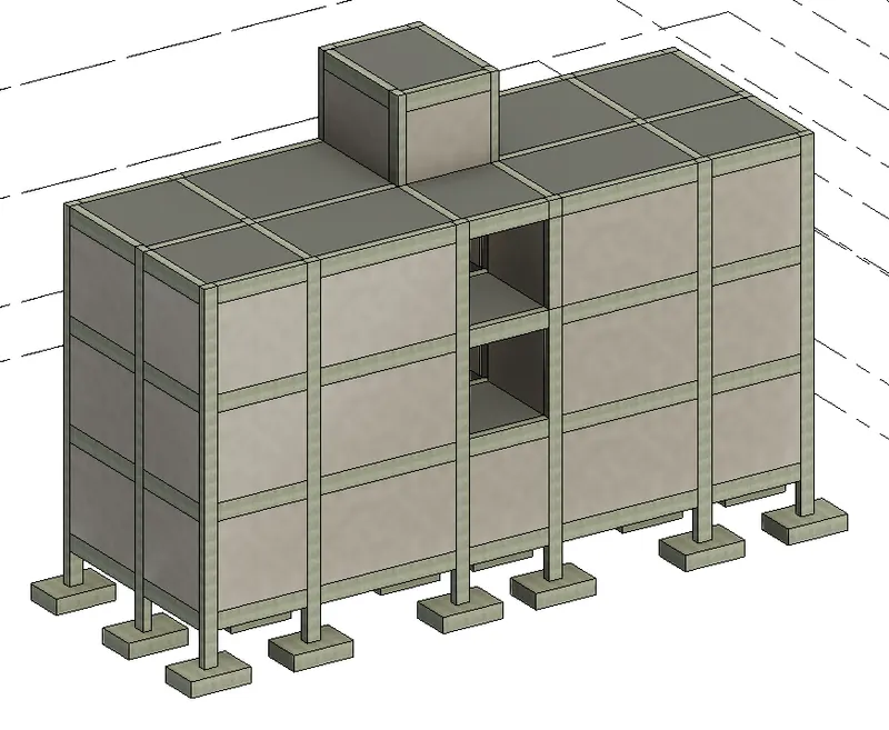
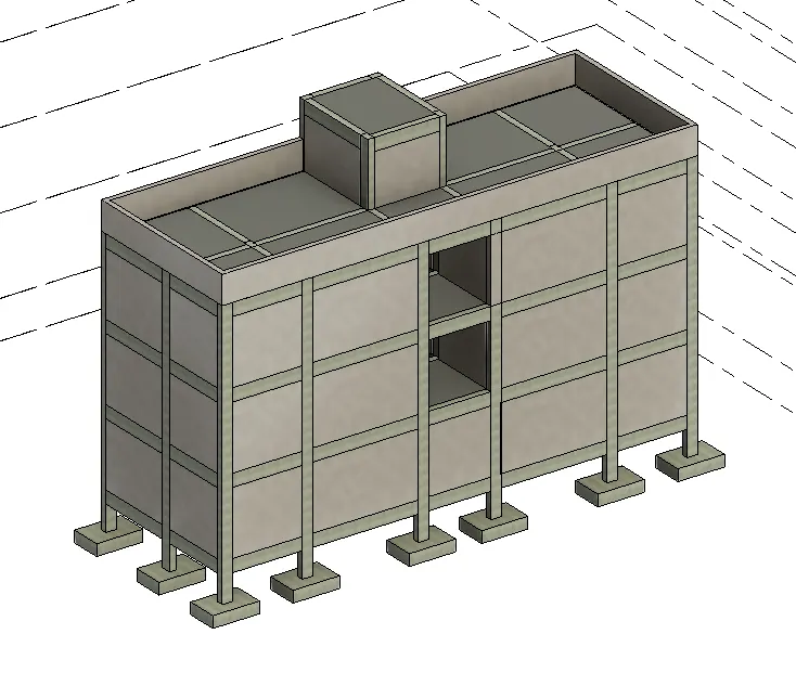
- Add the parapet walls at the roof deck.
***************
b. Exterior façade with fancy finish
PROCEDURE:
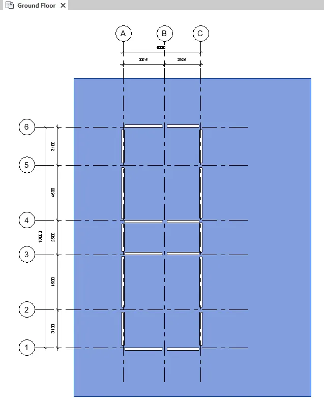
- To design the exterior of the building, create the boundary space using the floor tool on the ground floor. ake sure that it follows the space alloted by the NBC. Use the floor tool under the architecture tab.
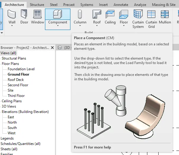
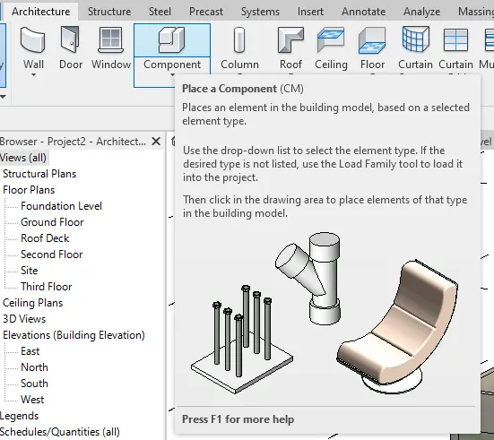
- Now add the exterior elements for thr building. Use the components tool under thearchitecture tab.
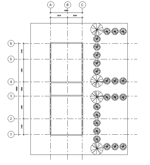
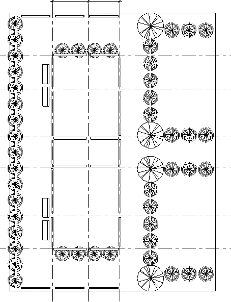
- Add trees and shrubs.
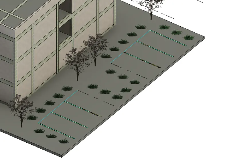
- Add Parking Spaces.
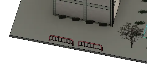
- Add bike stands.
- Add benches and such.
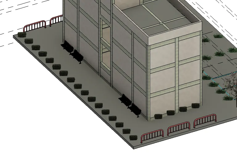
- Then check 3D if as desired.
***************
c. Interior partition walls to size rooms
PROCEDURE:
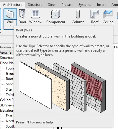
- Now create the partition walls per levels. Use the wall tool under architecture tab.
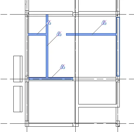
- Mirror on the other side and copy to all floor levels.
***************
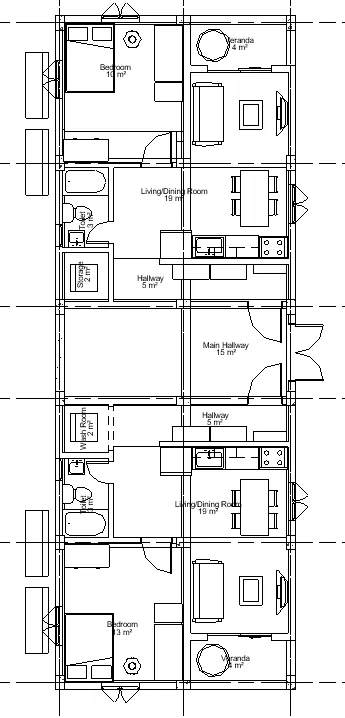
d. Components to add details to a room ( Desk, Chair, Lighting, Plumbing fixtures)
PROCEDURE:
- Add the interior omponents using the component tool under the architecture tab.
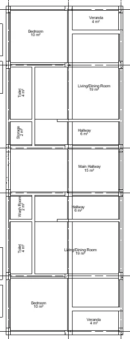
- First, add the rooms and room seperator using the Room tool under architecture tab. Remember to rename the room tags according to its purpose.
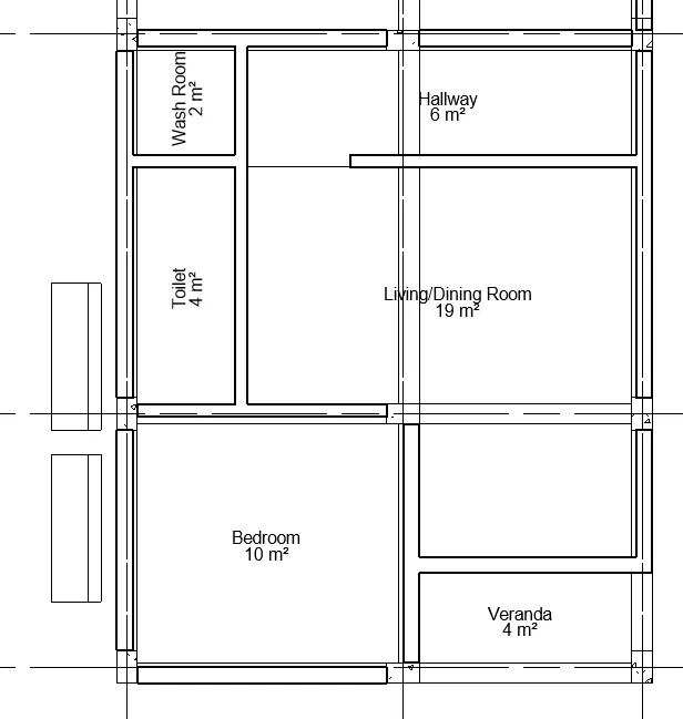
- Now add the components with respect to the room.
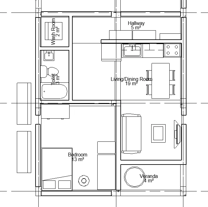
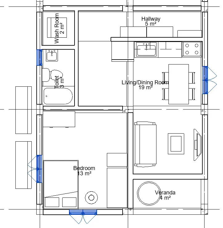
- Mirror the components and copy to all levels. Do the same for doors and windows.
- Add the windows.
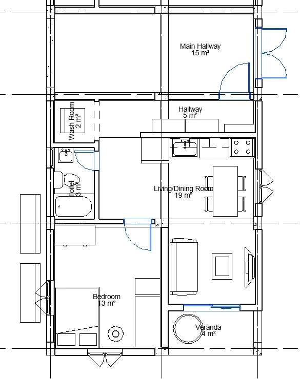
- Add the doors.
***************
e. Add components such as stairs Elevators
PROCEDURE:
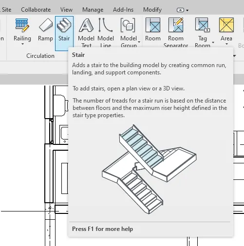
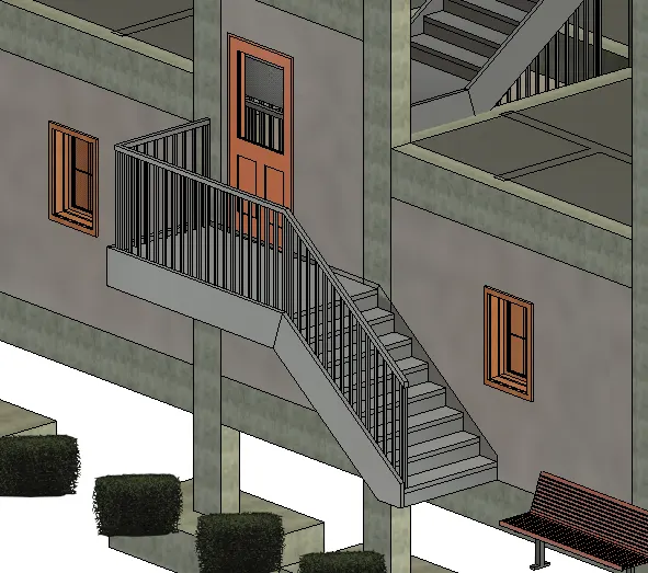
- Once the components are finalized, set the stairs using the stair tool under the architecture tab.
- Use the stair tool under the architecture tab to create the stairs.
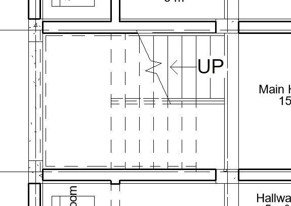
- Connect the stairs to all the levels.
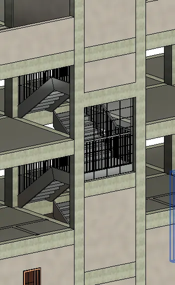
- Check for other stair locations and add them.
***************
f. Have at-least one side of the building with curtain walls and glass panels
PROCEDURE:
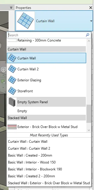
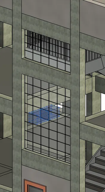
- To create the curtain walls, change the wall to a curtain wall in the properties tab.
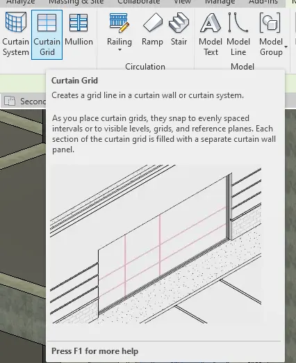
- When the wall is changed to a curtain wall, go to the architecture tab and select the Curtain grid to add patterns to the curtain wall.
***************
g. Include interior and exterior lighting fixtures
PROCEDURE:
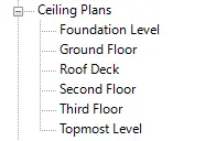
- To add the lighting fixtures, enter the ceiling plans and add the ceilings.
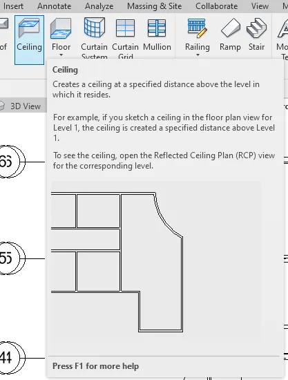
- Create the ceiling boundaries to create the ceiling.
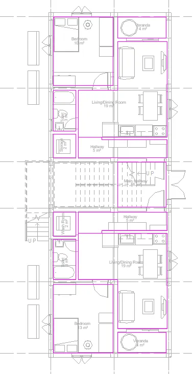
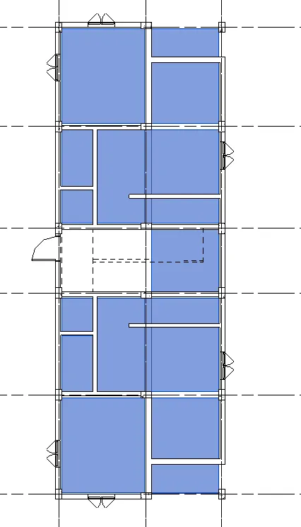
- Once the ceilings are placed, time to add the lighting fixtures.
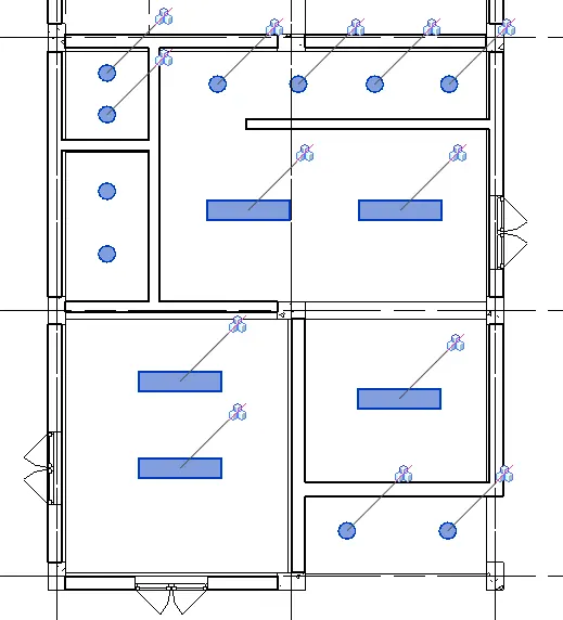
- Mirror to the other side and copy to all levels.
***************
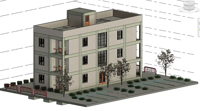
h. Place proper topographic components from outside ( Trees, Parking, Plants) to add details to the model
PROCEDURE:
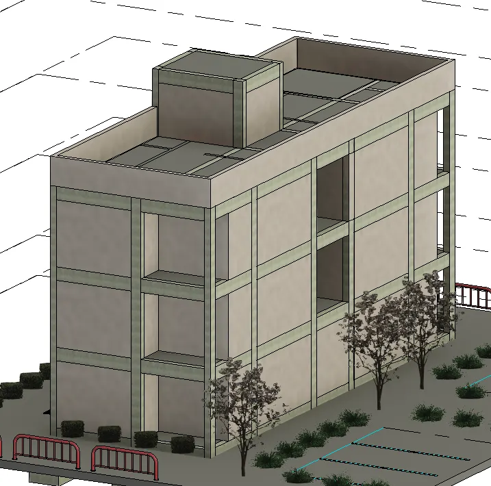
- Add the trees, parking, plants and other architectural elements using the component tool under the architectural tab.
- Once finished, the model will look like as below.
***************
5) Provide a set of drawings in an architectural and structural model to list the following details with categories and appropriate sheet templates included
General
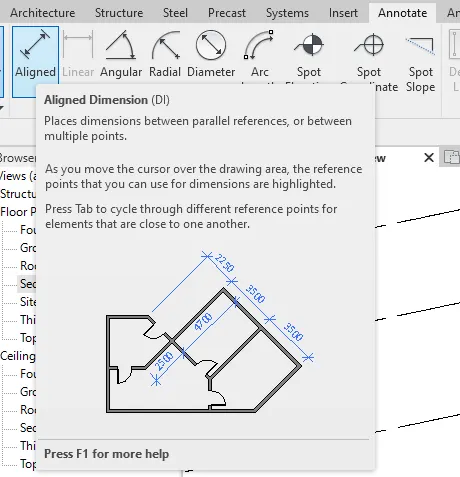
- To add dimension, go to annotate tab and select the aligned tool.
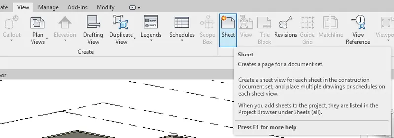
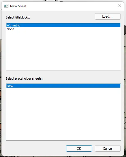
- To add a sheet for drawing view, select the Sheet tool under the View tab.
- Load a new sheet with corresponding title block.
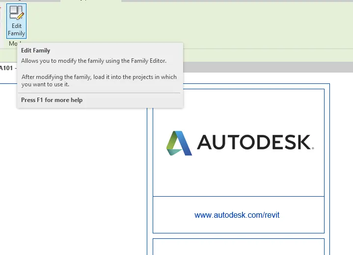
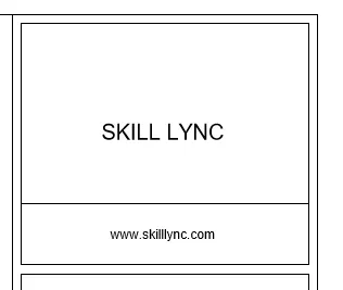
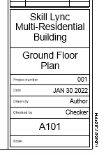
- Revise the title block as follows.
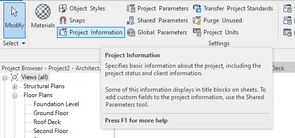
- The other marks will be as described in the project parameters. To edit the project parameters, go to the Manage tab and select project information.
- Check the created titleblock and edit its parameters using the parameters tab.
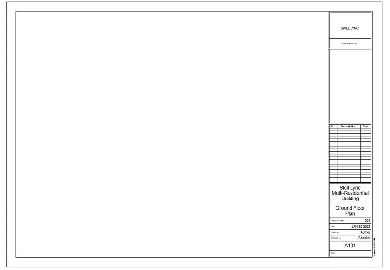
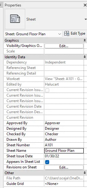
- Do the same for all the created sheets.
***************
a. Floor Plans with Annotations
PROCEDURE:
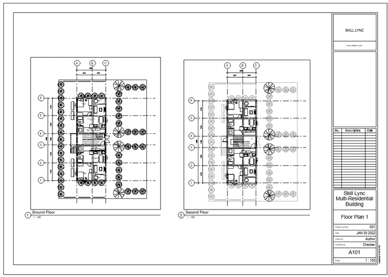
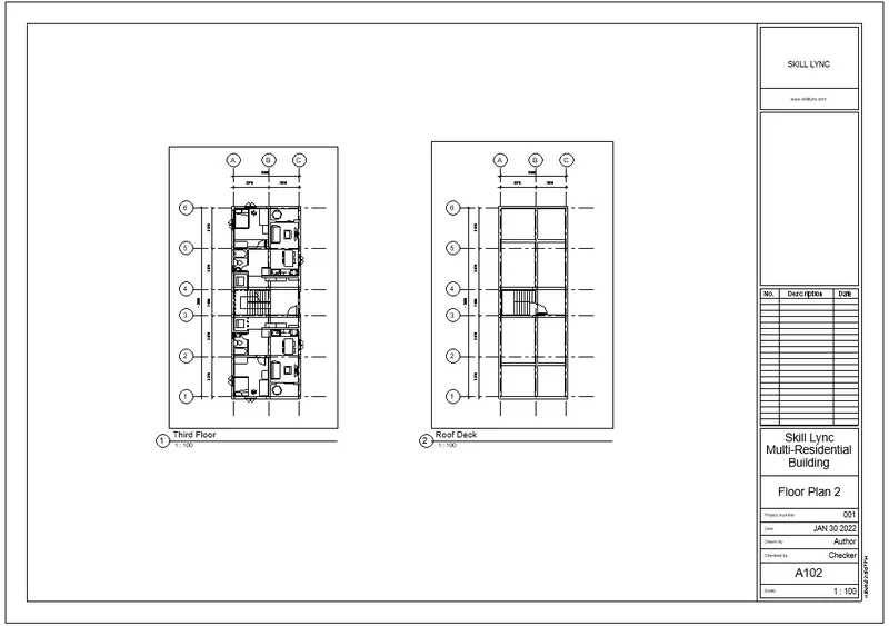
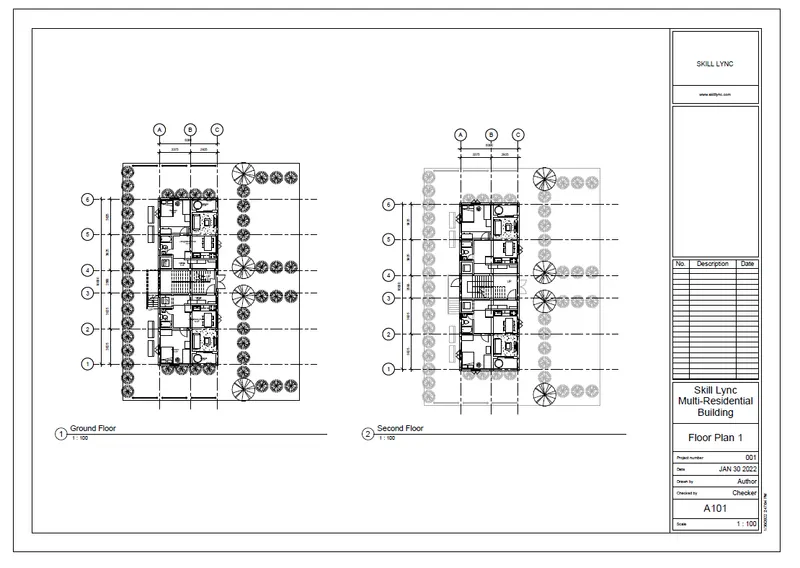
- Create a sheet using the sheet tool and change the title to floor plan 1.
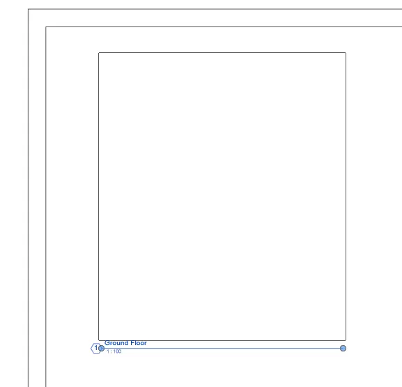
- To add a view to the sheet, go to view under the View tab.
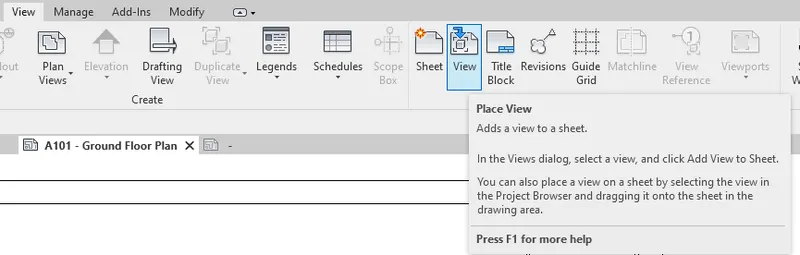
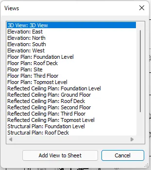
- Select the views to add and position on the sheet.
--> A101 - Ground Floor and Second Floor
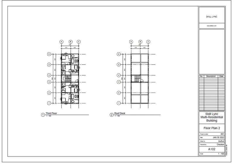
--> A102 - Third Floor and Roof Deck
***************
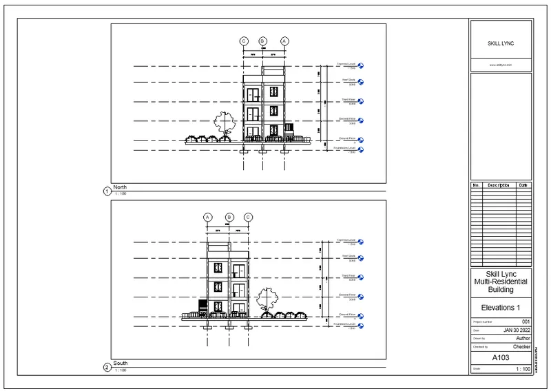
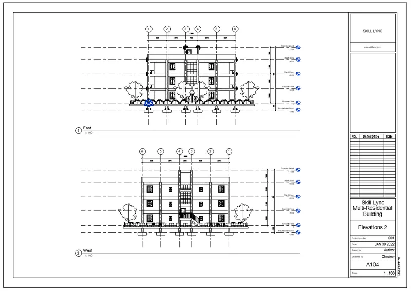
b. Elevations
- Do the same procedure for the elevations.
PROCEDURE:
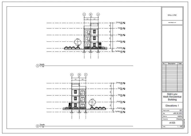
--> A103 - North and South Elevations
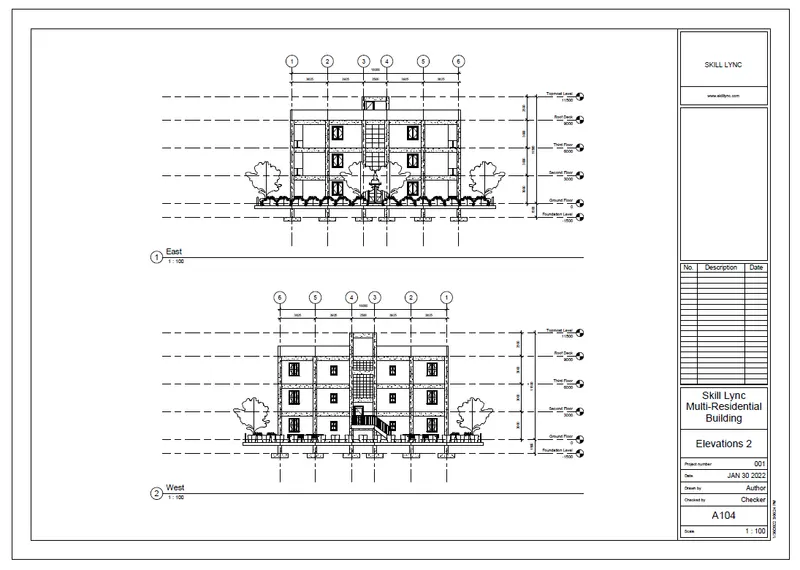
--> A104 - East and West Elevations
***************
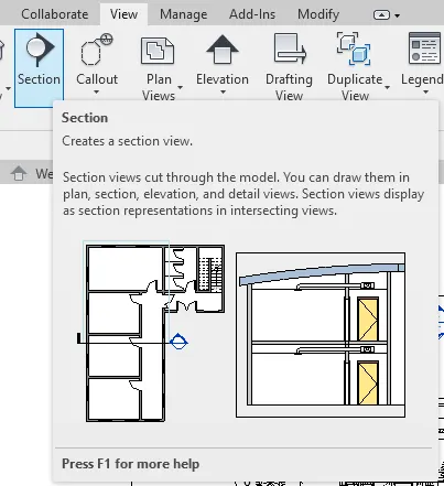
c. Sections
- To add sections, go to the desired plan view and use the Section tool under the architecture tab.
PROCEDURE:
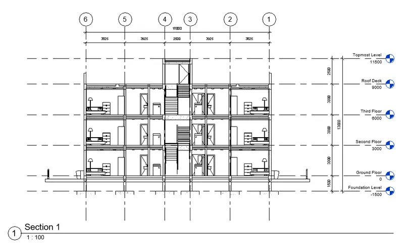
- Create the sections and add it to the sheet the same as the plan and elevation.
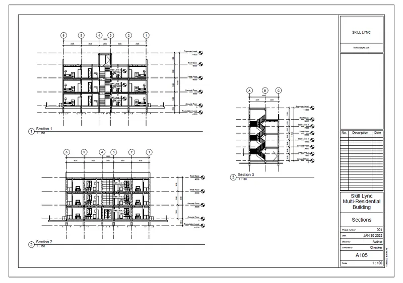
-->Section 1 (Bedroom, Toilet and Wash room)
-->Section 2 (Living, Dining, Veranda, Kitchen)
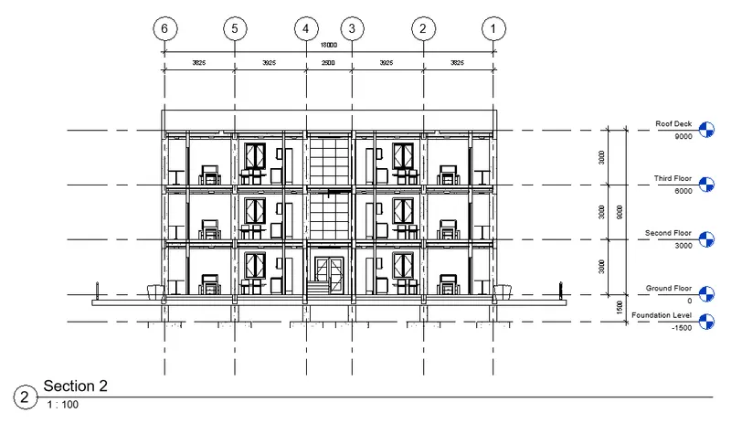
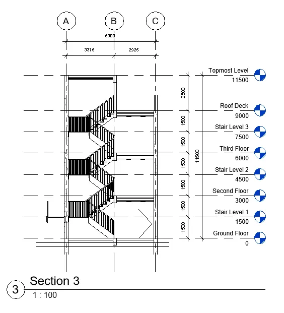
--> Section 3 (Stair Layout)
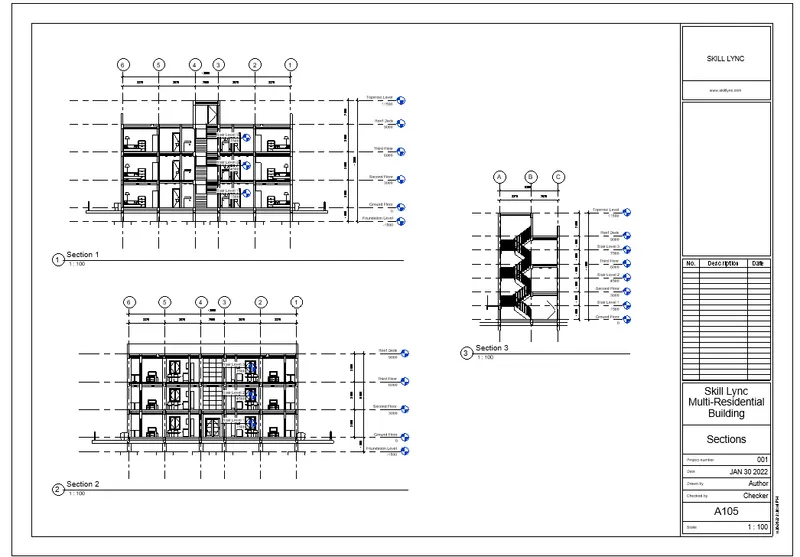
--> A105 - Sections 1, 2, 3
***************
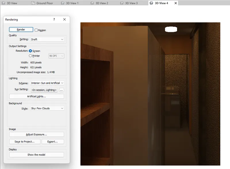
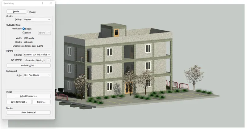
6) Using the Rendering settings, Render images of the 3D model produced and include the rendered images to the drawing sheets
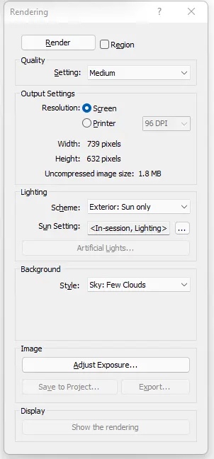
- To show the rendered view, first create camera view using the camrea tool under the view tab and 3D view.
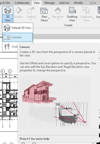
- Now go to the created 3D views and render the image.
***************
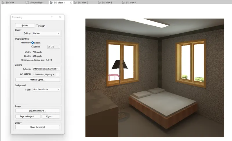
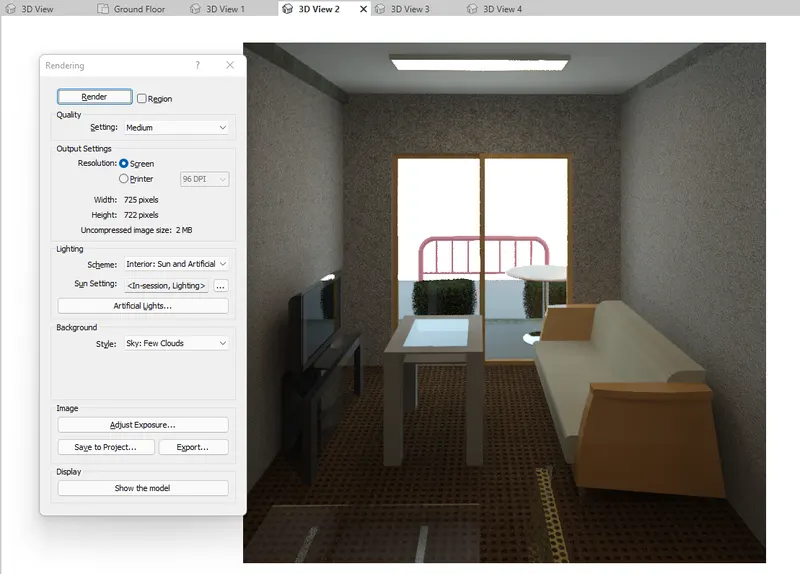
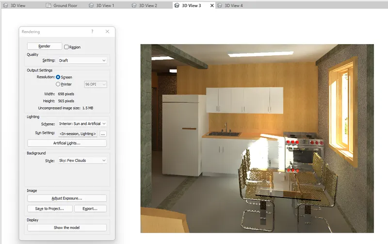
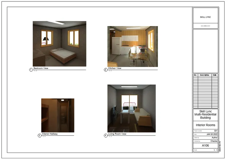
a. Rendering from interior rooms
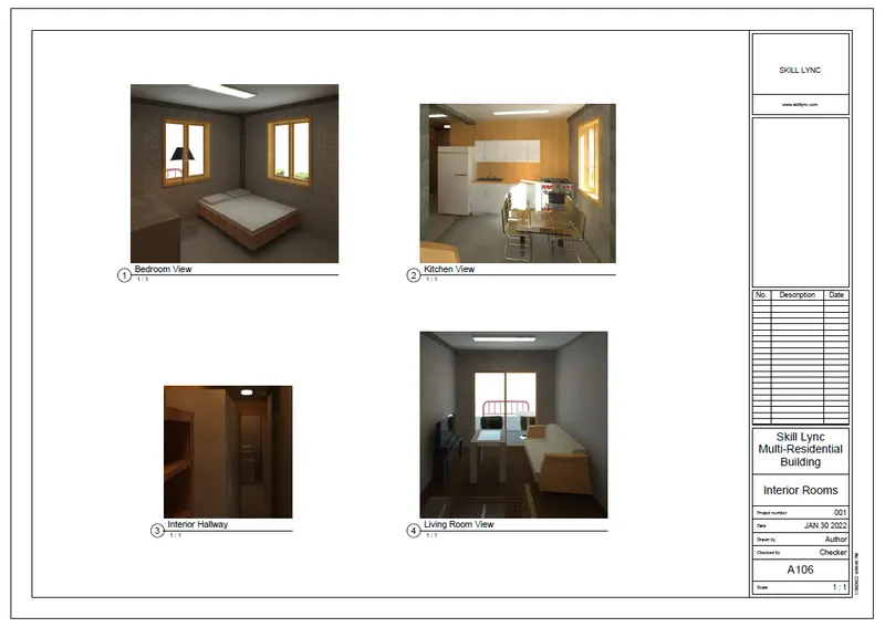
--> Rendered Bedroom
--> Rendered Living Room
--> Rendered Kitchen
--> Rendered Room Hallway
--> A106 Interior Rooms
***************
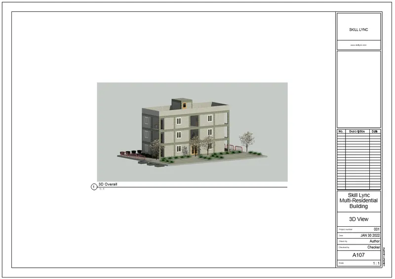
b. Rendering from out showing topographic features
--> Rendered Outside 3D view
--> 3D View
***************
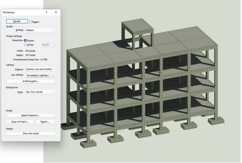
c. Rendering through structural framing
--> Rendered Structural View
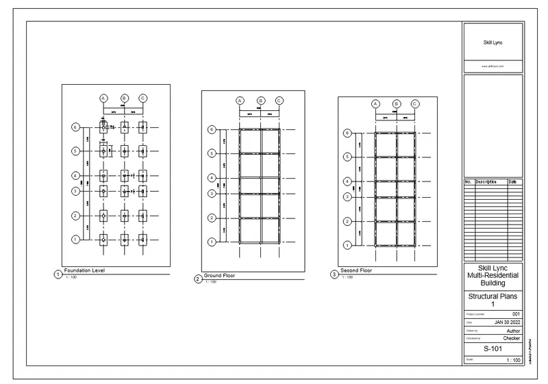
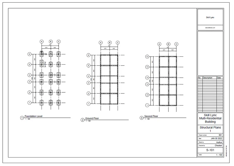
--> Structural Plans 1 (Foundation and Ground Floor Plan and Second Floor Plan)
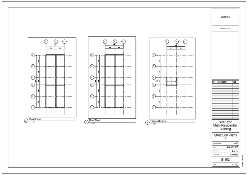
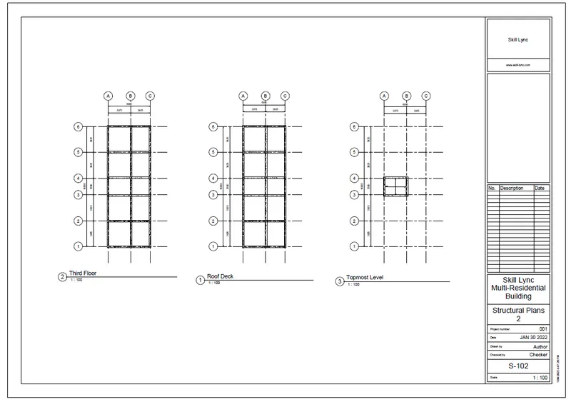
--> Structural Plans 2 (Third Floor Plan, Roof Deck and Topmost Plan)
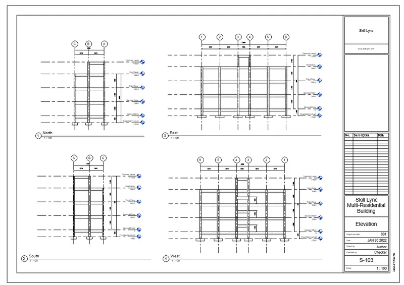
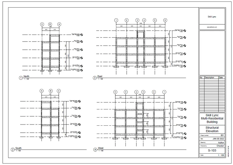
--> Structural Elevations (North, East, South, West)
***************
7) Print the set of drawing sheets created and submit the drawings from the architecture and structure model
PROCEDURE:
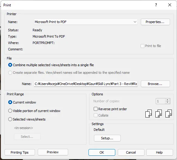
- To print the sheets into PDF format, on the sheet view, press CTRL+P.
- The print dialog box will appear.
- Select as below and Save with Appropriate name.
- Once the files are saved as PDF, it will look like this.
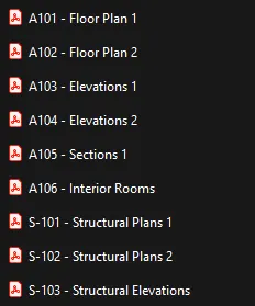
--> A101 - Floor Plan 1
--> A102 - Floor Plan 2
--> A103 - Elevations 1
--> A104 - Elevations 2
--> A105 - Sections
--> A106 - Interior Rooms
--> S-101 - Structural Plans 1
--> S-102 - Structural Plans 2
--> S-103 - Structural Elevations
********************************************************
3 Conclusion
***************
The Revit Software is a revolutionary software that allows the collaboration between multi-discipline engineering. It gives the the environment where multiple persons with different expertise can share the same workspace to perform a single project. By collaboration of a different number of models with designated disciplines, they can freely check and organize the structure through visualization and coordination.
Aside from modeling, the revit software allows the creation of construction plans and drawings that can be used for client presentation and construction. This goes bothways to each discipline that works within the project.
The revit software can be used to partake in the completion of a single structural building with its purpose. With the guidance given by the National Building Code of an area, the modeling of a structural building will have credibility, strength, and beauty.