Creating Architectural and Structural model with 3D rendering using REVIT
7.Creating Architectural and Structural model with 3D rendering using REVIT.
Aim: To select type of structure we want to draft and document to ensure that building satisfies all requirements as per NBC with respect to safety, sustainability, cost effectiveness, aesthetics etc.,
Introduction: Here in this session, I have selected 5-unit School building.
Considering this as Project -1
I am modelling 5-Unit School building. The Plot size is assumed to be 100m x 100m (10000 Sqmts).
In this project, we create the topography of the site using 'Massing and Site' tab and creating features like trees, parking components, street lights, etc.,
In this project we create a school building of 5-unit and develop the model by adding walls, partitions, furniture, ceilings, roofs, doors and windows and other components.
Question 01) Select the type of structure you want to build from one of the three below:
a. Multi-Unit Residential Apartment
b. Office Buildings.
c. School.
Answer: 1) Here we have selected a school of 5 storey.
Question 02) Assume reasonable assumptions for geographic and location details for your project modeling. Based on assumptions and type of structure selected identify the modeling requirements from NBC.
Answer:
Aim: To give reasonable details for Geographic and Location of the Project.
Procedure:
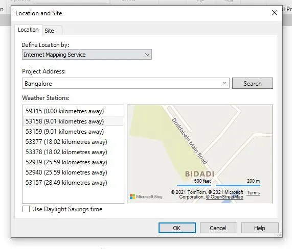
- Location – Doddabele Bengaluru- 5-unit School Building.
- The geographic and location details are assumed as shown.
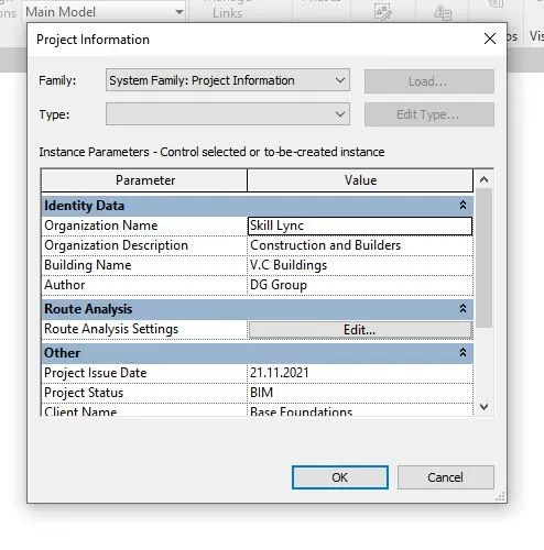
- Go to the ‘Manage tab’ and feed the project information as below. Now in the ‘manage tab’ Click on the ’Location of Project’ Give the project coordinates.
- Now note down the Modeling requirements for ‘Educational Building’ asper NBC.
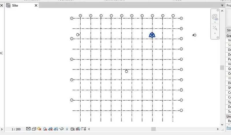
- Now in the ‘Project browser’ go to ‘site’ and click on ‘Grids’ on Structure tab to draw Longitudinal Transverse Grids.
Result:
Question 03) Using the structural model, include the following components based on the type of structure selected
a. Foundation – Isolated / Wall/Matt Foundation
b. Columns
c. Beams Connected to Columns
d. Roof Framing/ Truss
e. Floor / Decks
f. Floor Openings for Elevators and Stairs.
Answer:
Aim: To add details such as Footings, Columns, Beams, Roof, Floor and Floor Openings as Elevators and Stairs.
Introduction: Structural elements such as columns, beams, footings etc., are load bearing parts of a structure. They contribute in safely and efficiently transferring permanent and variable loads to a bearing strata.
Hence, they need to be properly designed to ensure stability of the structure.
Procedure:
- Open the Drawing created in Week 6.
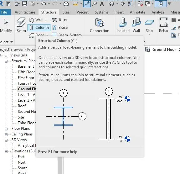
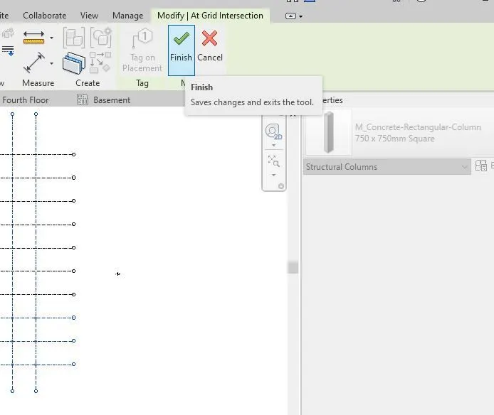
- Now go to the ‘Structure tab’ click on the ‘Columns’, In the ‘Properties’ Select the size of the footing. (We have selected 750mm x 750mm Square columns).
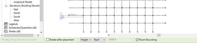
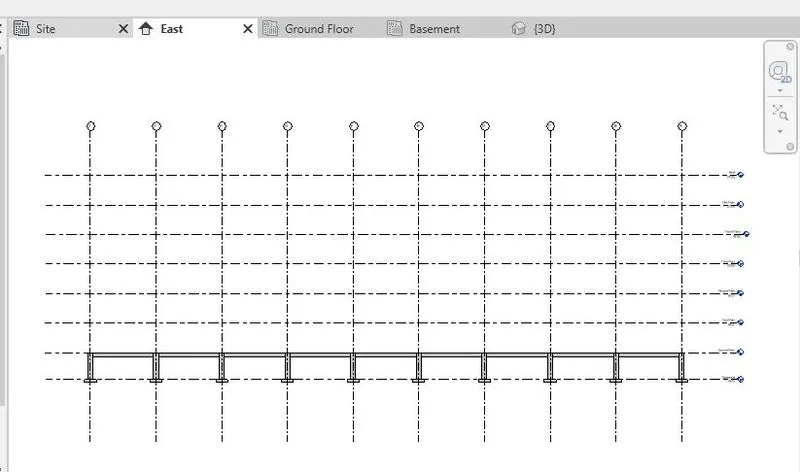
- Now select the Height of the columns to the ‘roof’. Now all the columns have been added.
- Now add the footings to the columns. Go to ‘Structure tab’ click on ‘Isolated’ and now in the ‘Properties tab’ select the size of the footing. Now in the ‘Modify tab’ click on ‘at column’ and ‘finish’ on modify tab. Now all the footings will be placed at the bottom of the columns.
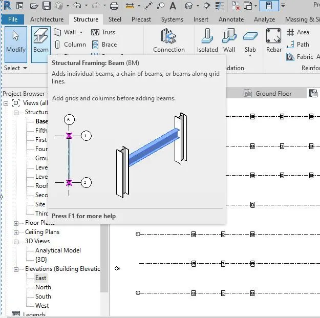
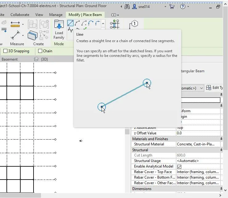
- Now in the ‘structure tab’ click on ‘beam’. In the ‘Properties browser’ select the size of the beams. With the help of ‘Line’ in the modify tab we place the beam in required places.
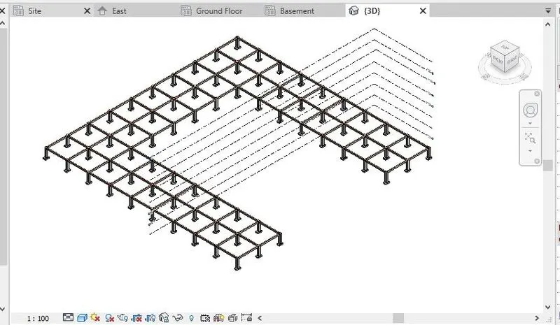
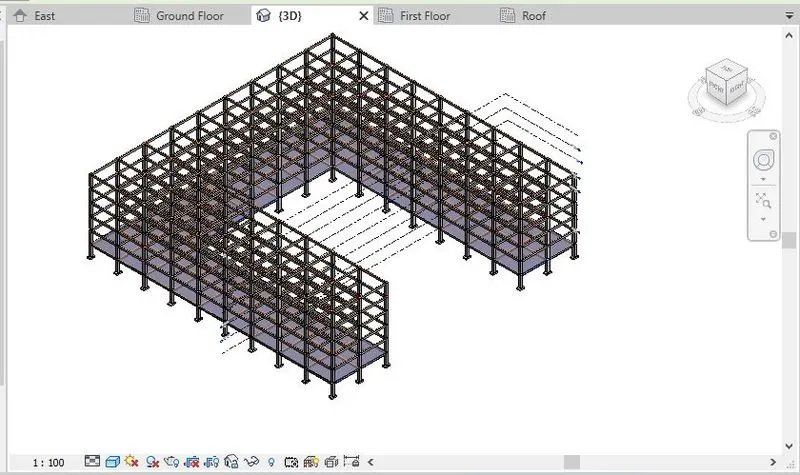
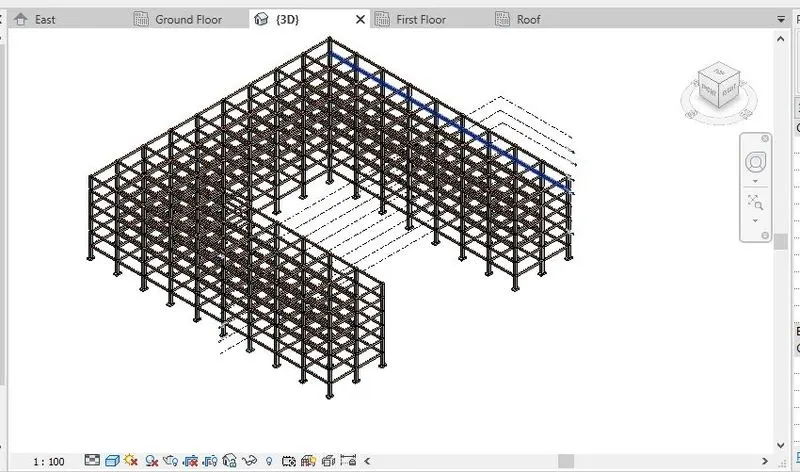
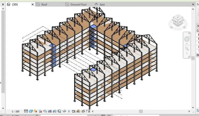
- Now we can view all the three column, beam and footing structure in ‘3D view’.
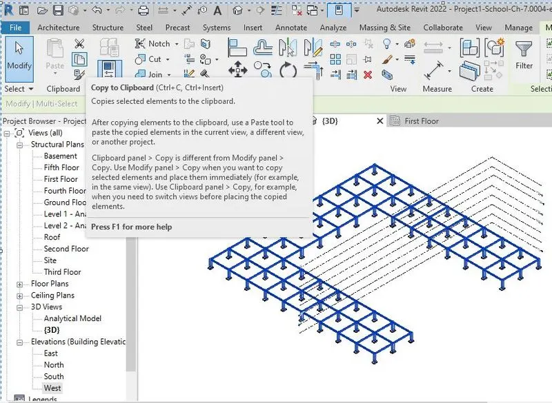
- Once the frame work in done in ground floor level, we can copy the same for upper floors. To copy the frame work select ‘all the beams and columns and
And go to ‘Modify tab’ in the select ‘filter’ and uncheck the ‘isolated footing’. Now go to copy and click on ‘paste on selected level’. The framework is pasted on all the Levels.
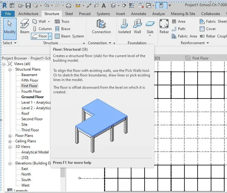
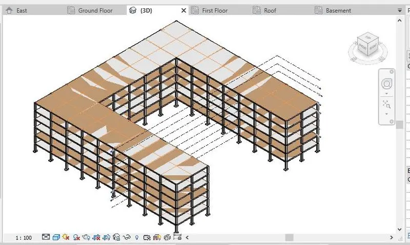
- Now go to the ‘structure tab’ and click on ‘floor’ and select ‘Structural floor’.
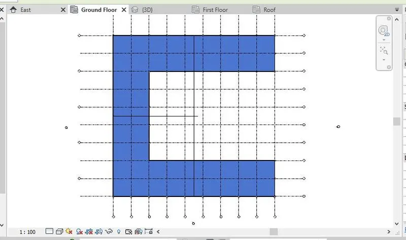
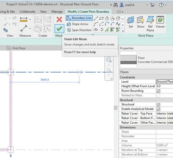
In the ‘Properties browser’ select the thickness of the floor and in the ‘Modify tab’ select the ‘Boundary line’ to create the floor boundary line and after selecting the boundary for floor click on ‘finish’.
Now the floor will be created in ‘ground floor plan’. Again, selecting the ‘floor’ using ‘modify’ we can copy paste the floor on all other levels.
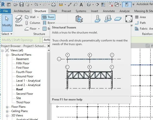
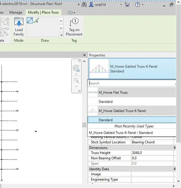
- To place steel truss of roof, go to the ‘roof level’ in project browser and then in ‘structure tab’ click on ‘truss’. Then from the ‘Insert tab’ Load family and add required truss.
Once the ‘Truss’ is shown in the property browser pick the ‘line’ command from ‘modify tab’ and place the truss at desired places.
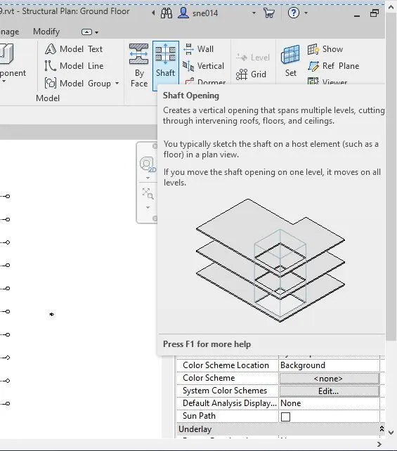
- To create openings for staircase or lift in the floors, in the ‘structure tab’ click on ‘shaft’ with the help of ‘Boundary line’ from ‘modify tab’ draw rectangles on the ‘ground floor’ where openings have to be created and finally click on finish button.
Now in the ‘properties browser’ select the unconnected height and specify the height of the opening need to be provided.
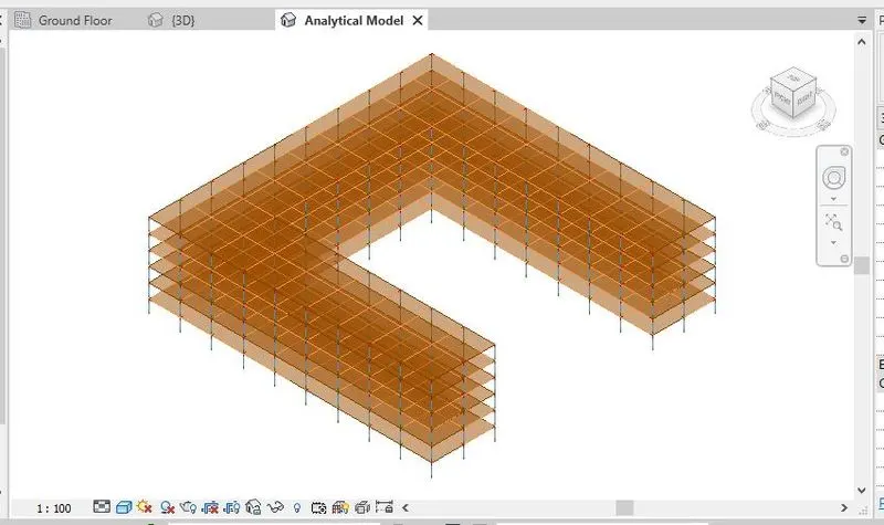
Now go to ‘3D model’ to view the openings created.
Result:
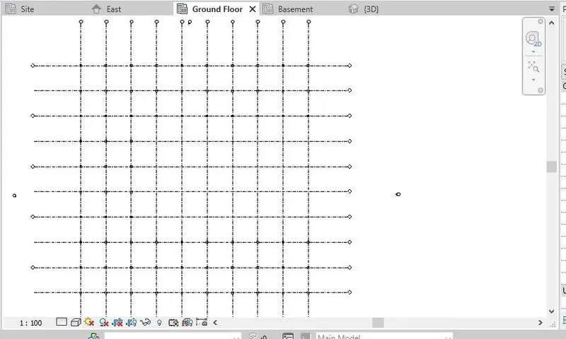
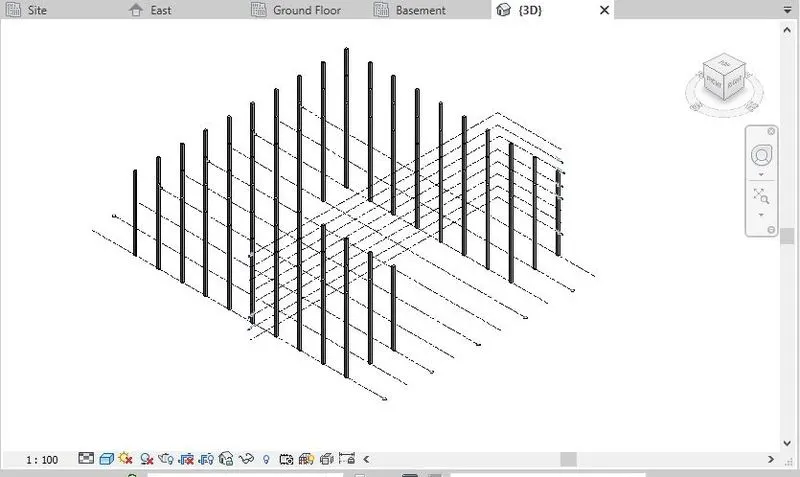
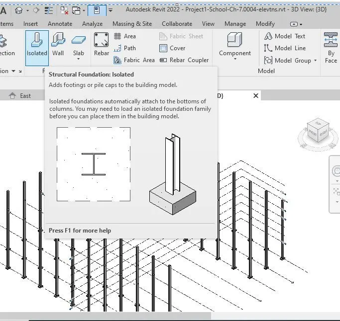
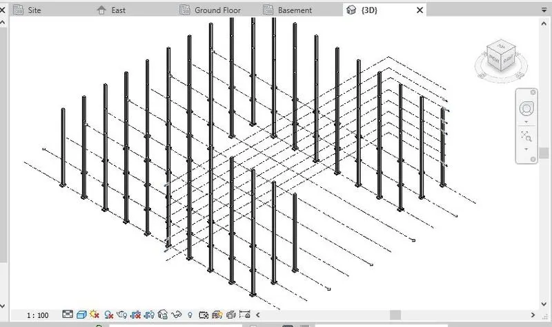
Question 04) Using the architectural model, include the following components based on the type of structure selected
a. Wall Layout with appropriate material and finishing
b. Exterior façade with fancy finish
c. Interior partition walls to size rooms
d. Components to add details to a room ( Desk, Chair, Lighting, Plumbing fixtures)
e. Add components such as stairs Elevators
f. Have at-least one side of the building with curtain walls and glass panels
g. Include interior and exterior lighting fixtures
h. Place proper topographic components from outside (Trees, Parking, Plants) to add details to the model.
Answer:
Aim: To import all the parameters created in ‘structural template’ to ‘Architectural template’ and now updating the project with architectural elements.
Introduction: Once the structure is framed in ‘structural template’ we have to import the parameters to ‘Architectural template’ to give proper Aesthetics to the building. In the ‘Architecture template’ we can add walls, staircases, lifts, partition walls etc.,
Procedure:
1) Open a new project ‘Architecture template’. Import all the elements created in ‘structural template’ to this project through “Link Revit’ from Insert tab.
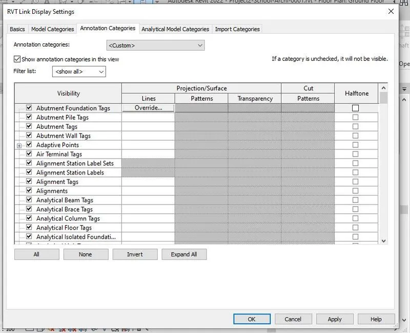
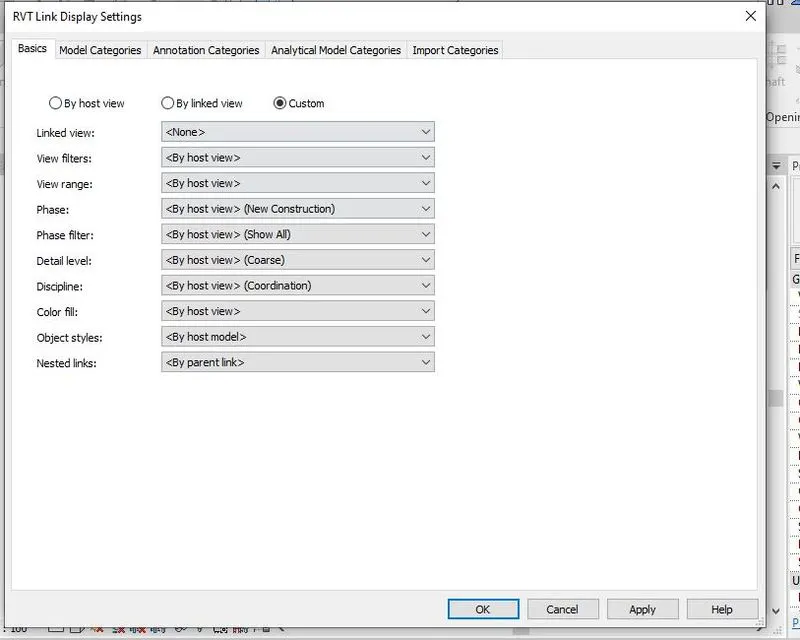
2) Once the elements are imported, now through ‘copy Monitor’ copy the grids to the ‘Architectural model’. Once grids are overlapping with others we can select to see only the copied grids by turning off the visibility settings of Linked Revit grids in the ‘visibility/graphic overrides in floor plan’.
Now, pin the grids so that location of the grids can’t be changed in the future work.
3) Now in the ‘project browser’ go to the elevations and in the same way copy the levels created in structural model to Architectural model using copy monitor.
Later turn off the visibility of overlapping levels by changing the settings in ‘visibility/graphic overrides in floor plan’.
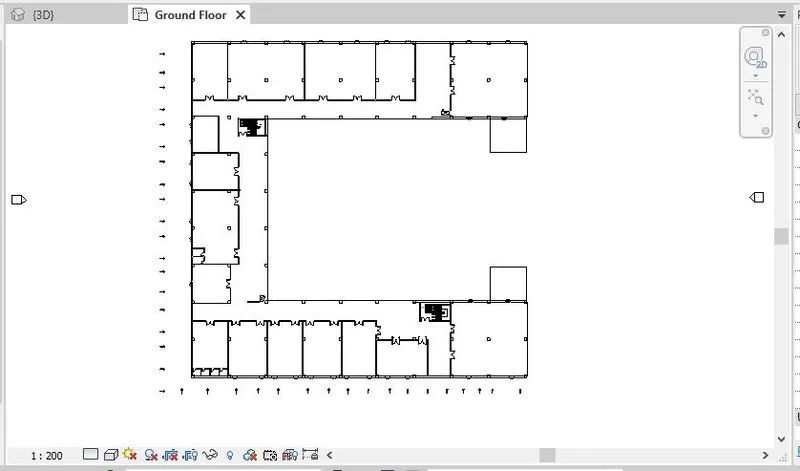
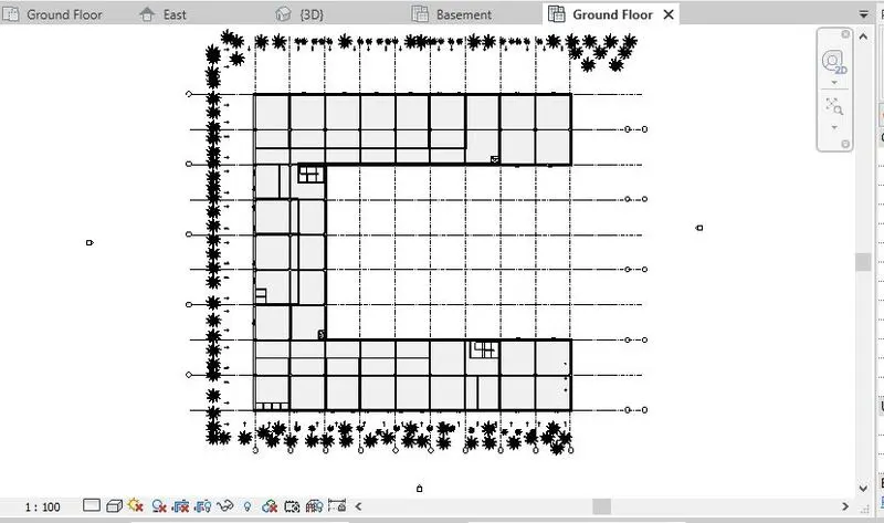
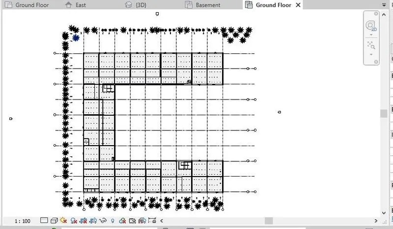
4) Now, to create the ‘Floor plans’ go to the ‘view’ toolbar and click on ‘Plan views’ and click on floor plan. Now in the new window select all the floor plans and select ‘ok’. Now all the floor plans from ‘Basement to Roof’ are created.
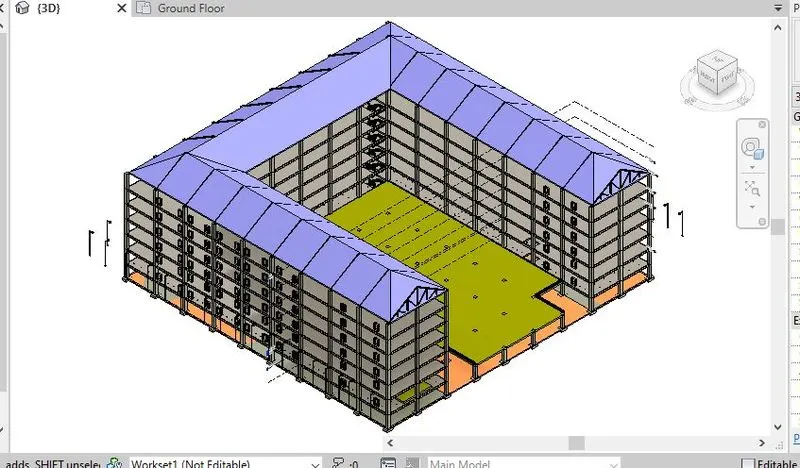
4) Once all the initial settings are done proceed with the Architectural modelling of the building as required. Build the Exterior walls first then one by one add other Architectural elements like interion walls, Stairs etc.,
5) Once the boundaries are set, now add the required components like Doors, Windows, Plumbing Fixtures, Class room Fixtures, Lightings etc.
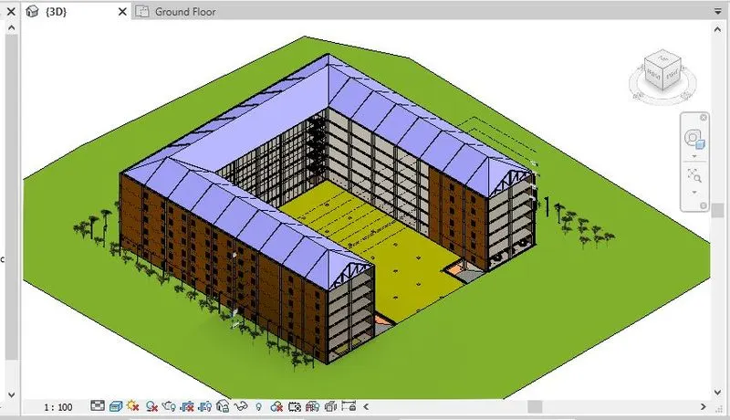
6)Now add the Topography for the building. (Plane ground levels are assumed) To add topography, go to the ‘Ground level’ in the floor plans and go to ‘Massing and Site’ toolbar and click on topography. Now add points around building and finish click on it. Now assign the material for the Topography as Grass.
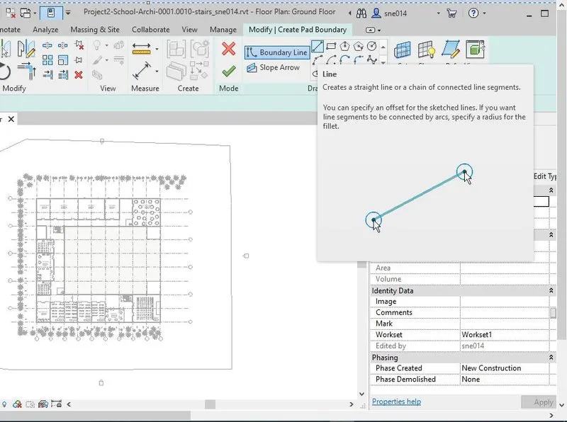
7) To separate building from the topography surface, click on building pad and in the modify tab click on line option to create boundary to building and in the “property Browser’ click the Level as Basement and click on finish icon.
8) Load Planting family from the Revit Library and add plants of wish around the building. Similarly Load Lighting Family from the Library and go on adding external lighting around the building.
Result:

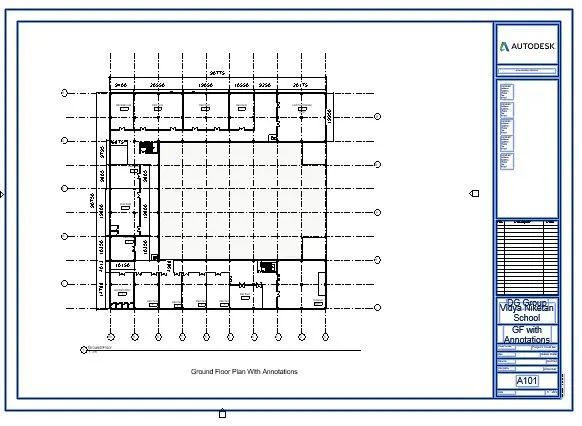
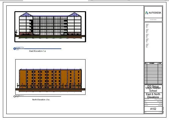
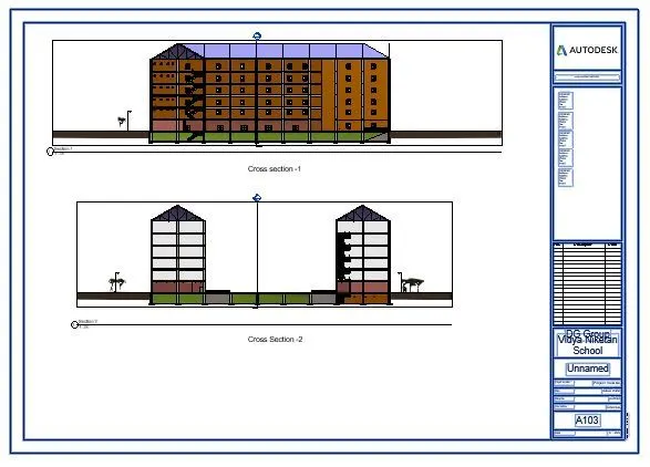
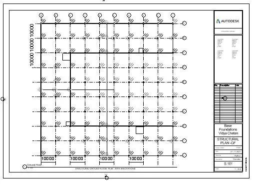
Question 5) Provide a set of drawings in an architectural and structural model to list the following details with categories and appropriate sheet templates included
a. Floor Plans with Annotations
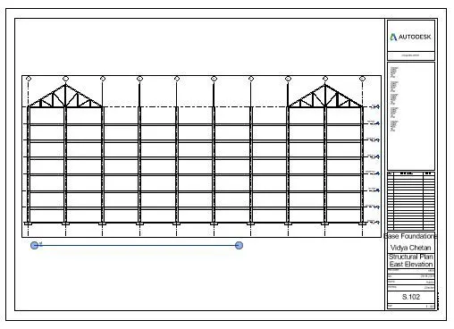
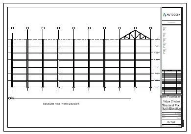
b. Elevations
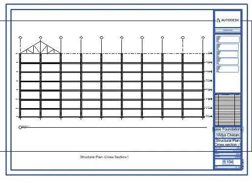
c. Sections
Answer:
Aim: To Create sheet templates of Architectural model and Structural model for the following drawings.
Introduction: For the proper presentation of drawings sheet templates are very much helpful in Revit Software. Sheet templates will give us details of the drawings for proper presentation and documentation.
Procedure:
- Open the Architectural Drawing Created in Last week. In the Project Browser go to the ‘floor plan’.
- Now go to ‘view’ toolbar and press ‘sheet’ and import sheet as per requirement. Now new window will open with sheet templates. Their edit the “project name, Client, Issue date, Company name etc., as per requirement.
- Now go to the ‘Place view’ and start selecting the Floor plans, Elevations and Cross sections that’s has to be presented in the drawing sheets.
- Now repeat the same procedure for Structural drawings.
Result:
Question 6) Using the Rendering settings, Render images of the 3D model produced and include the rendered images to the drawing sheets
a. Rendering from interior rooms
b. Rendering from out showing topographic features
c. Rendering through structural framing
Answer:
Aim: To render images of the 3D model created in the week 6 challenge and to include images from interior rooms and from outside the building showing topographic features and also rendering images from structural drawings.
Introduction: Rendering images will produce images that look closer to the real images as it provides greater details and a better understanding of the project to be constructed in the future.
Procedure:
1) Open the Architectural model created in the earlier assignment.
2) Go to the project browser and click on the ‘3D Views’ created earlier.
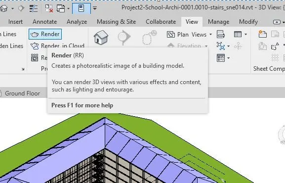
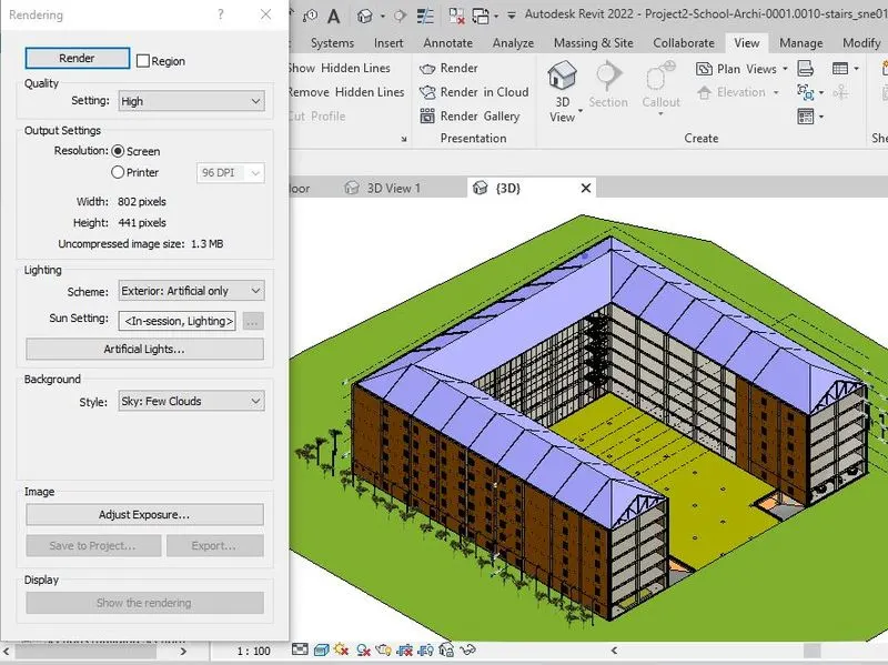
3) Now go to the ‘view’ icon on toolbar and press ‘Render’. A small window will appear. Here settings have to adjusted to get better quality images.
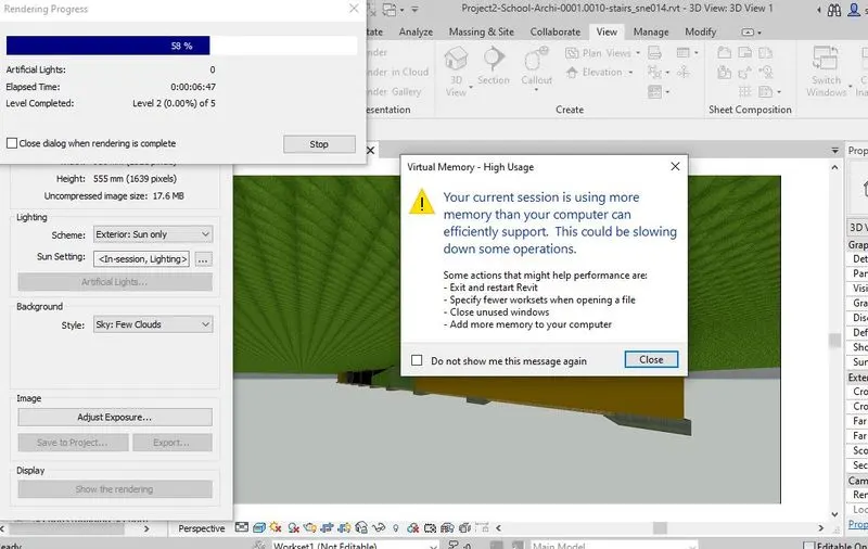
First set the quality of the image as medium, printer resolution, Lighting arrangements, background style as per your requirement and then click on ‘render’.
Could not process rendering images as computer cannot support good quality images rendered by Revit.
Sorry.
Result:
Question 7) Print the set of drawing sheets created and submit the drawings from the architecture and structure model.
Answer:
Aim: To print the sheets created in Architectural and Structural model.
Procedure:
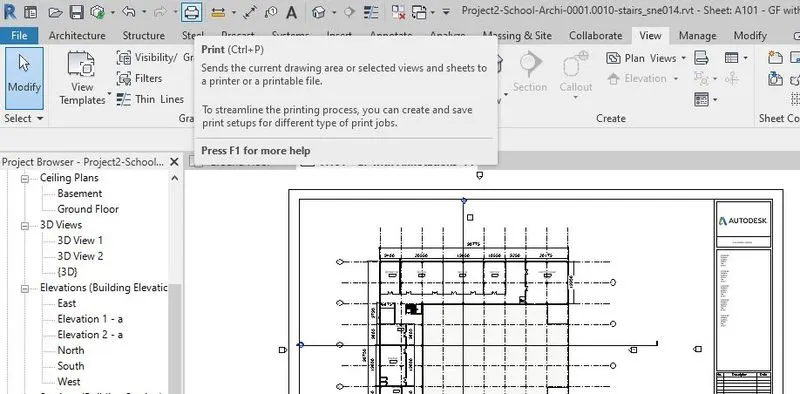
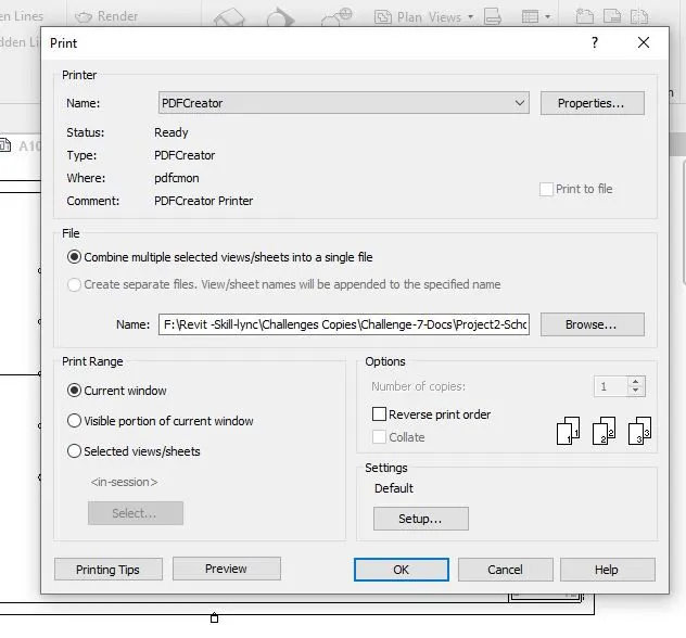
- Go to the project browser and click on the sheets created. Now press ‘Print’ option in the toolbar.
- Now print sheets created in A1,A2 and A3 papers as per the requirements.
Result: