Creating Architectural and Structural model with 3D rendering using REVIT
1] Select the type of structure that you want to build one of the three below
- Multi-unit residential Apartment
- Office building
- School
Answer = From the above options that given to build a building i want to build multi-unit residential apartment
2]Assume reasonable assumptions for geographic and location details for your project modelling.Based on assumptions and type of structure selected identify the modelling requirements form NBC.
Answer =
The Geographical and location details for my project modelling,based on the assumptions of multi-unit residential apartment
Selected identify the modelling requirements from NBC
- As above mentioned by the building comes under the residential category and it can be situated in the centre of the city
- The project is lacated 200 m in the highway nearest
- Road width of the project is
- The height,area limitation and safety measure are followed by the NBC.2005.
- The height of the project is
- The project height in meter is m and road width is m,the height of the building should not exceed 1.5 times the width of the road
- In case of buildi ng height is not exceed,so it is suitable for construction
3] Using the structural model,include the following components based on the type of structure selected
- Foundation- Isolated/wall/matt Foundation
- Columns
- Beams connected to columns
- Roof framing/truss
- Floor/Decks
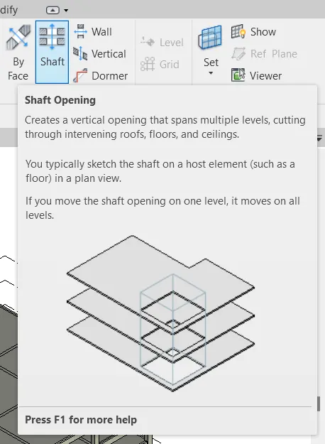
- Floor Openings for Elevators and stairs
Answer =
Aim = To using the structural model,include the following components based on the type of structure like wall,windows,doors,foundations,beams etc.
Commands used :-
- Architectural template
- Structural template
- Grids
- Columns
- Beams
- Foundations
- Stairs
- Shafts
- Floors
Procedure :-
- Open a architectural template in revit software and save it as residential building Architecture 001
- Then draw the grid lines and specify co-ordinates 0'0" for both horizontal and verical grid lines
- Click the collaborate tool and save the project
- NNext open the new structure tempolate,save it as residential building Structural 001
- Repeat step 2 and step 3 ,and save the file
- Create a new architectural templates and add the architectural and structural links using manage the links options
- Select the acquired co-ordinates and set the links to the current co-ordinates
- Now Start drawing the structural components of the project in the structural template
- Draw the vertical and horizontal grid lines, and also set the levels
- The Foundations,ground floor,first floor,second floor,third floor and roof levels are created
- Select column option from the structural tab and draw columns at intersections points of the grids
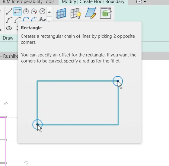
- Repeat the same process, draw the structural components foundation, beam,floor,and save the project to centarl file
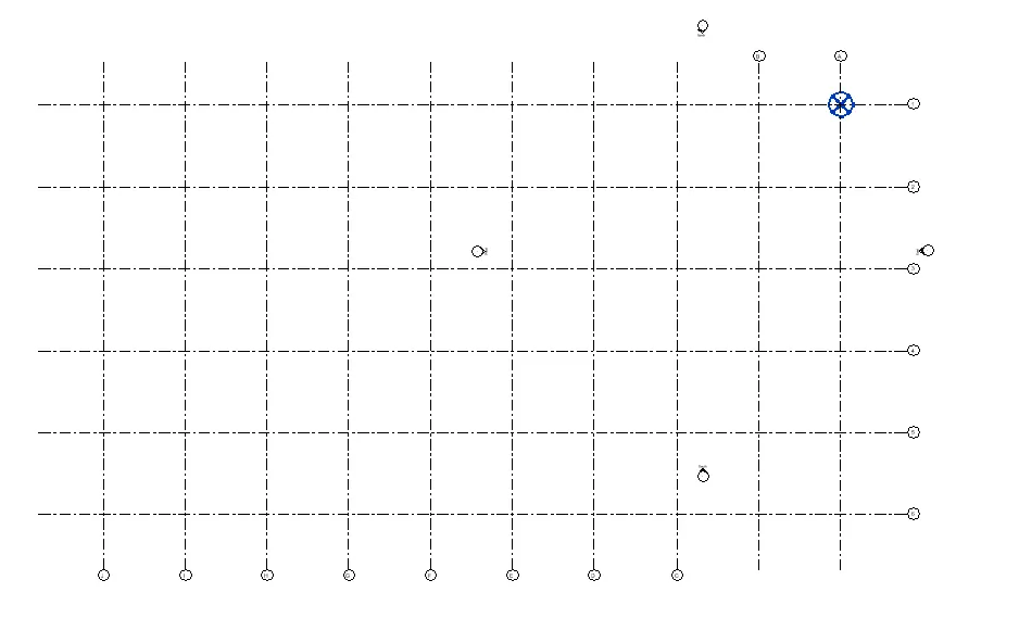
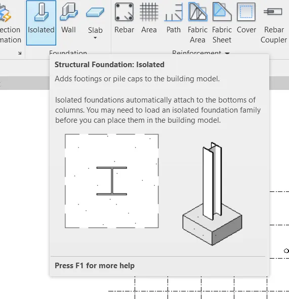
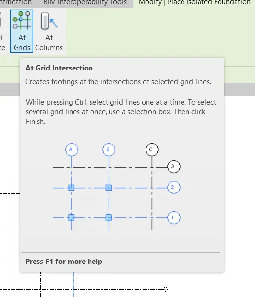
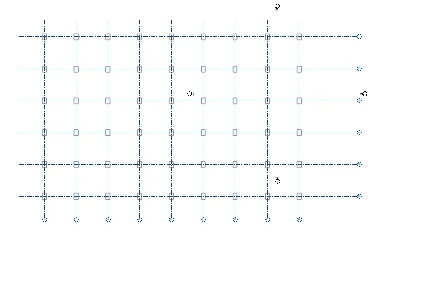
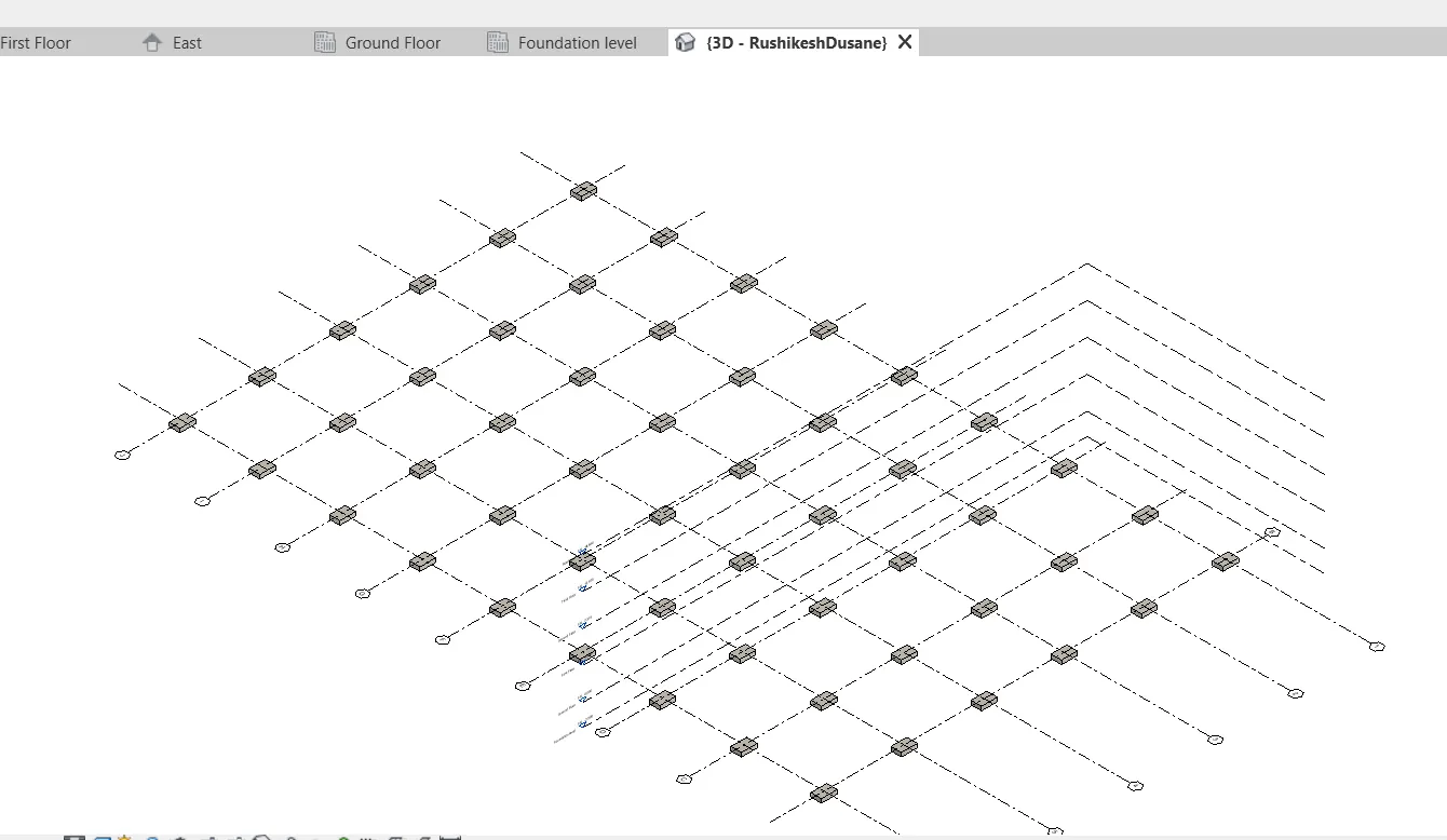
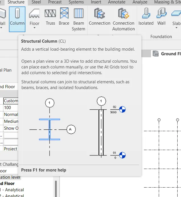
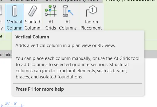
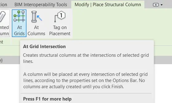
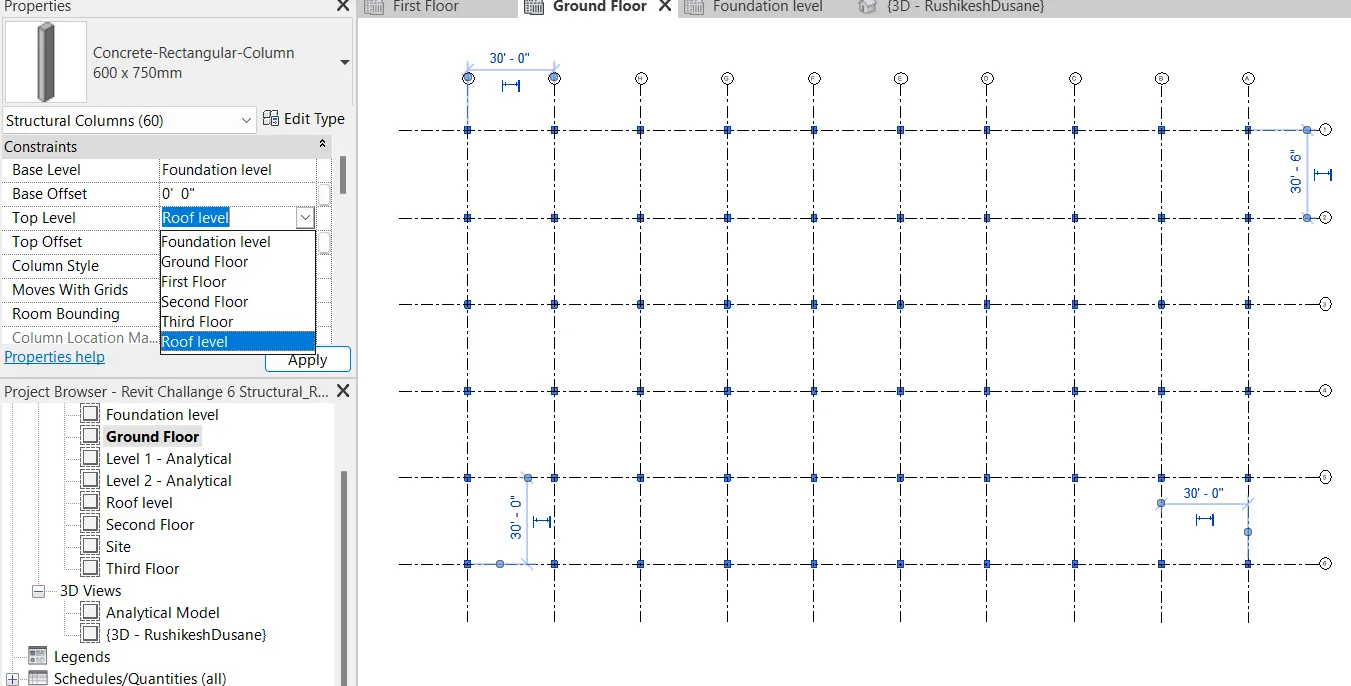

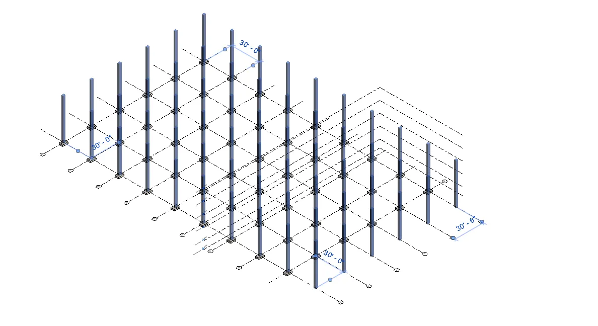
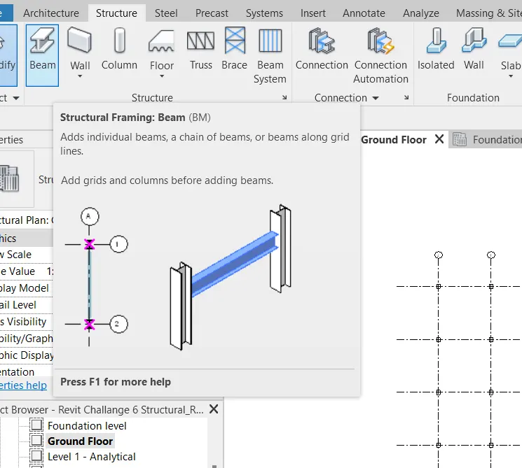
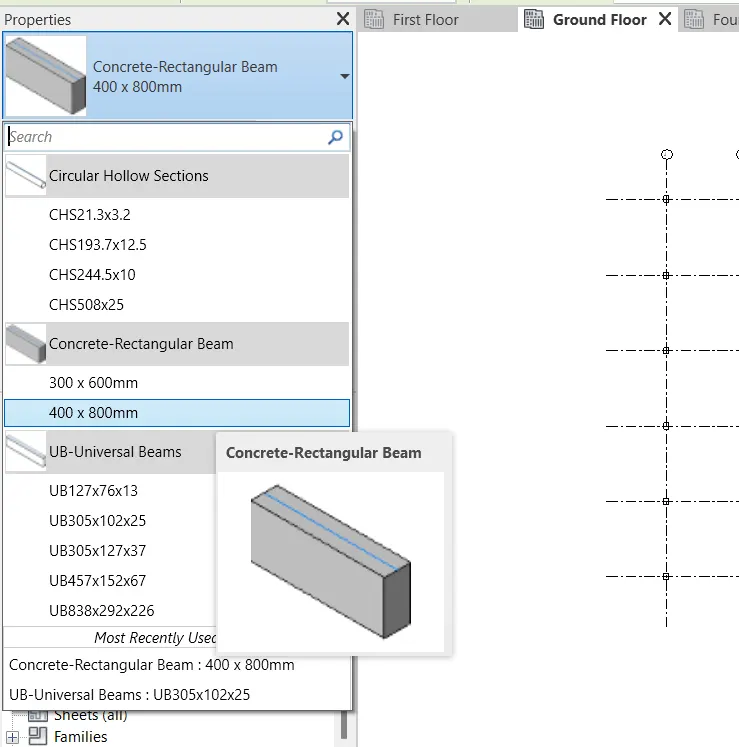
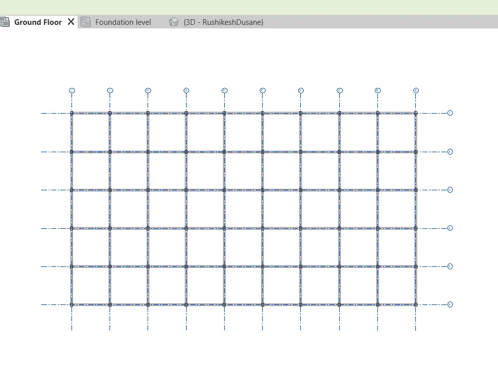
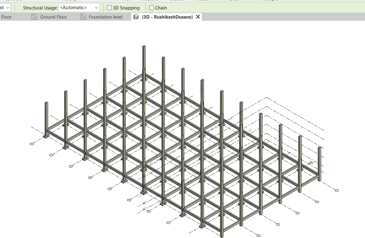
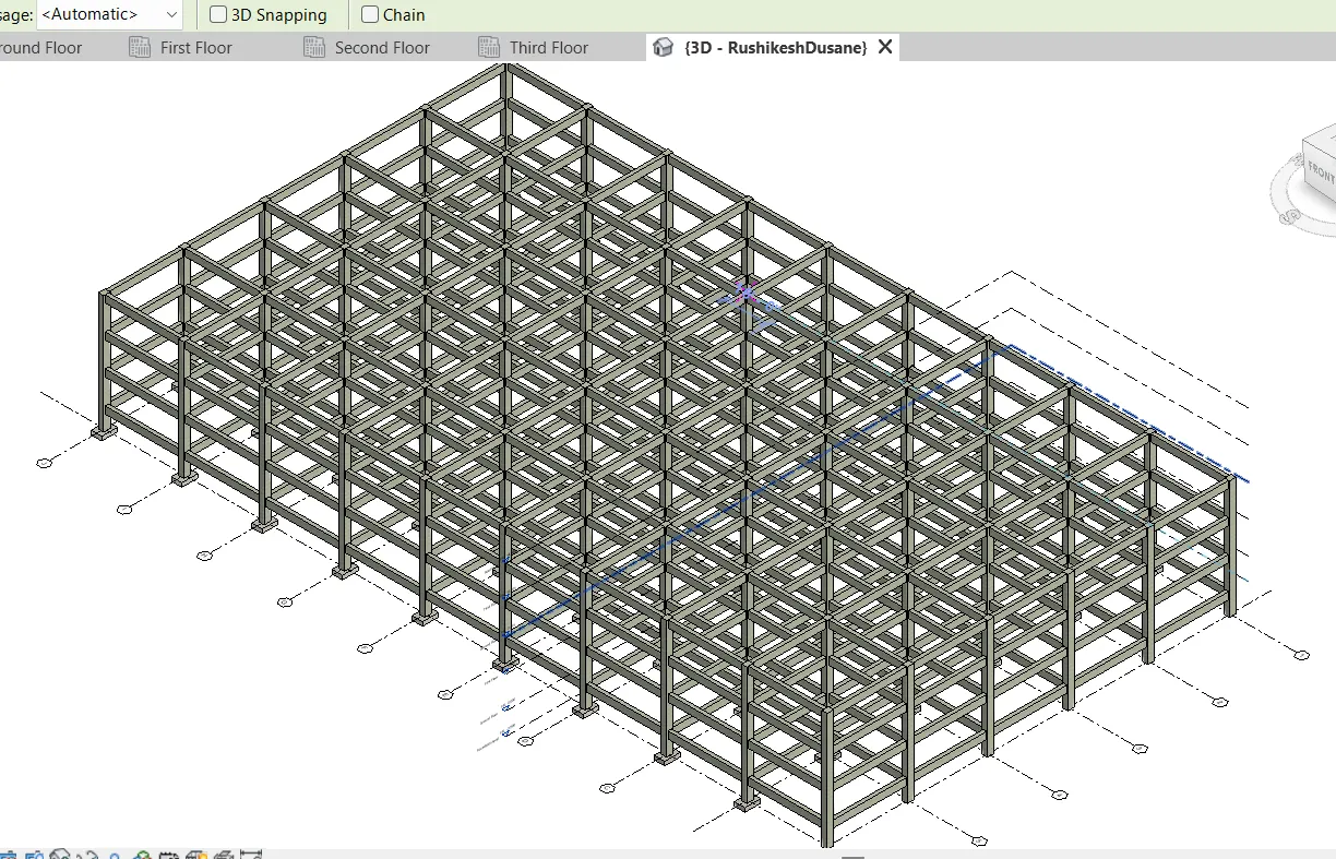
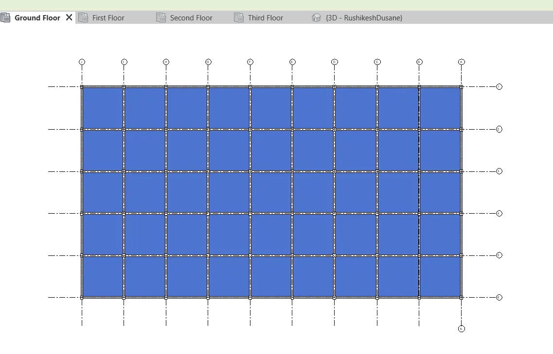

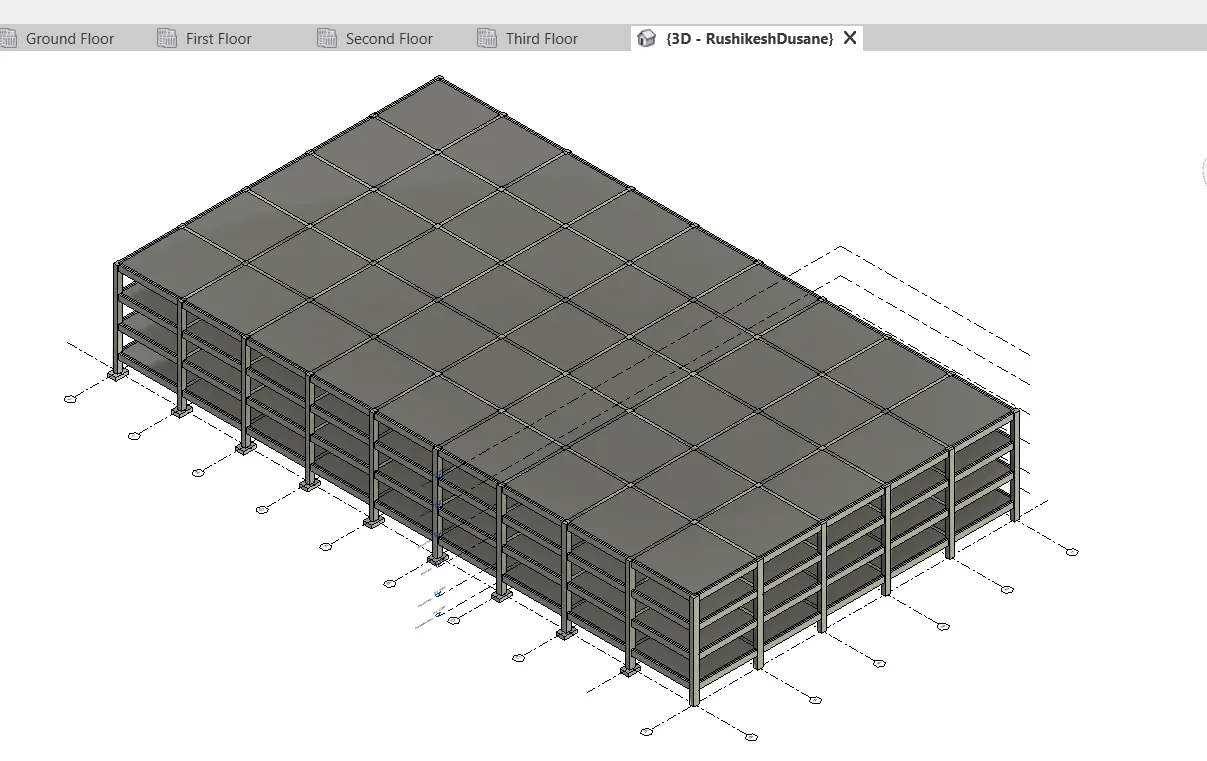
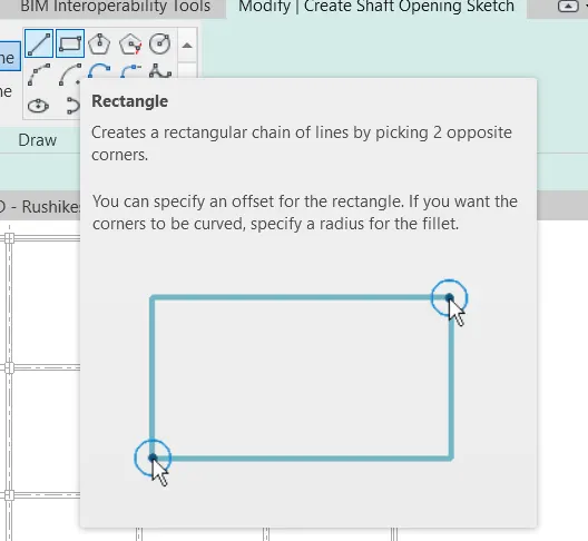
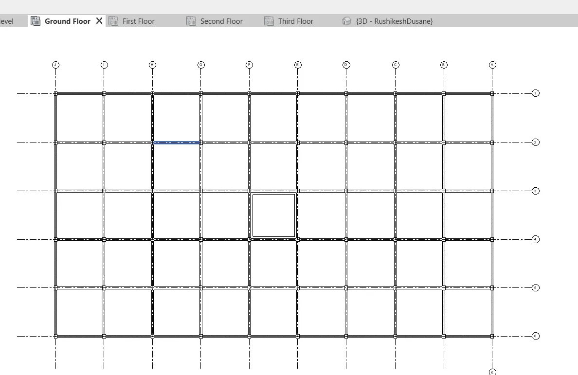
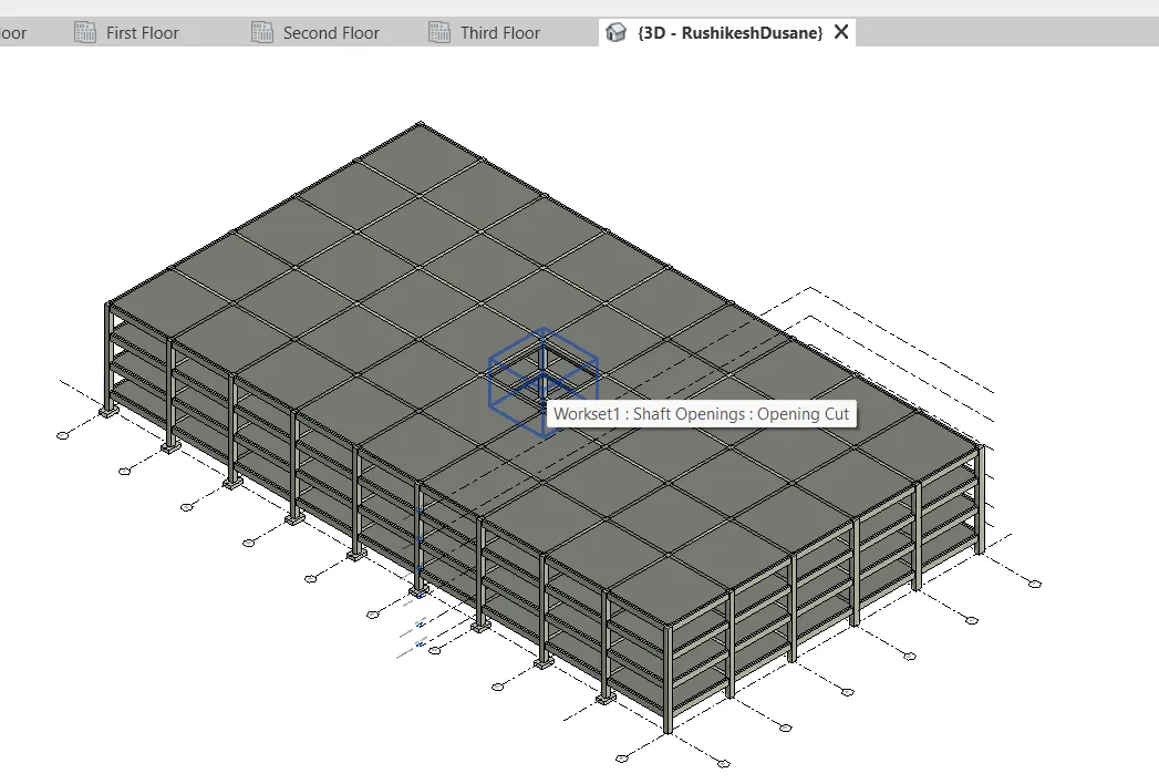
Result :- In this project using structural model and save it as a collaborate as central file
4) Using the architectural model,include the following components based on the types of structure selected
- Wall Layout with appropriate material an finishing
- Exterior facade with fancy finish
- Interior partitions walls to size rooms
- Components to add details to a room(Desk,Chair,Lighting,Plumbing Fixtures)
- Add components such as stairs elevators
- Have at-least one side of the building with curtain walls and glass panels
- Include interior and exterior lighting fixtures
- Place proper topographic components from outside(trees,Parking,plants) to add details to the model
Answer :-
Aim :- To using the architectural model,include the following components based on the type of structure selected above.
Commands Used :-
- Architecture
- Walls
- Components
- Load family
- Ceiling
- floor
- Doors
- Windows
- Staircase
- Railings
Procedure :-
- Now go to the architectural template which has created before in this file
- Copy the grids which were created in the previous structure template and copy it
- With the help of paste from clipboard option paste the grids in the architectural template
- Select the grids and pin it
- Click the elevation and create the levels required from architectural tab
- click virtual graphics setting and select custom in annotation offf the grids
- Now ,Start create the exterior wall ion the grid lines
- And then floor tool and add the floor to all levels of projects
- Same wall tool select all select for all levels
- Also add stairs to all levels in it
- By creating the stairs inn the project add railing to the stairs
- Not forget to add door,windows to the walls
- Set the camera in all rooms to view the pictures in realistic of building
- Save the project and changes will done in the architectural template will be save to be centralised files
RESULT =
RESULT:
- Set the camera in all rooms to view the pictures in realistic of building
5) Provide a set of drawings in an architectural and structural nmodel to list the follwing details with categories and approprioate sheet templates included
- Floors plans with annatations
- elevations
- sections
Answer=
AIM = To provide a set of drawings in an architectural and structural nmodel to list the follwing details with categories and approprioate sheet templates included
Commands are used:
- Render
- region
- style
- scheme
- sheet
Procedure =
- Open 3d view and set the view to take the picture where we want to render the area
- then click view menu and click render option
- render dialog box are appears
- Select region option and crop the image in region
- then render image will be appears into more realistics than other and iot can used to better presentation of our client also
RESULT =
RESULT =
6) Using the rendering settings render images of the 3D model produced amd include the rendered images to the drawing sheets
- REndering from interior rooms
- Rendering from out showing topographic features
- rendering through structural framing
ANSWER =
AIM = To Using the rendering settings render images of the 3D model produced amd include the rendered images to the drawing sheets
Procedure =
- Open 3D view abd set the view to take the picture where we want to render area
- Then click view menu and click render option
- Render dialog box are appears
- select region option and crop the image region
- Then we can change the styele of renser images
- then the render image will be apperas
Result=
- then the render image will be apperas
Result=
7) Print the set of drawing sheets created and submit the drawings from the architecture and structure model
Answer=
AIM= Print the set of drawing sheets created and submit the drawings from the architecture and structure model
Procedure =
- Click the views and open file menu and click the print
- Print dialog box is appear
- then change the settings of sheets size texts styles page setup everything
- then click print and press ok
Result =