Creating Architectural and Structural model with 3D rendering using REVIT
QUESTIONS
1) Select the type of structure you want to build from one of the three below:
a. Multi-Unit Residential Apartment
b. Office Buildings
c. School
2) Assume reasonable assumptions for geographic and location details for your project modeling. Based on assumptions and type of structure selected identify the modeling requirements from NBC
3) Using the structural model, include the following components based on the type of structure selected
a. Foundation – Isolated / Wall/Matt Foundation
b. Columns
c. Beams Connected to Columns
d. Roof Framing/ Truss
e. Floor / Decks
f. Floor Openings for Elevators and Stairs
4) Using the architectural model, include the following components based on the type of structure selected
a. Wall Layout with appropriate material and finishing
b. Exterior façade with fancy finish
c. Interior partition walls to size rooms
d. Components to add details to a room ( Desk, Chair, Lighting, Plumbing fixtures)
e. Add components such as stairs Elevators
f. Have at-least one side of the building with curtain walls and glass panels
g. Include interior and exterior lighting fixtures
h. Place proper topographic components from outside ( Trees, Parking, Plants) to add details to the model
5) Provide a set of drawings in an architectural and structural model to list the following details with categories and appropriate sheet templates included
a. Floor Plans with Annotations
b. Elevations
c. Sections
6) Using the Rendering settings, Render images of the 3D model produced and include the rendered images to the drawing sheets
a. Rendering from interior rooms
b. Rendering from out showing topographic features
c. Rendering through structural framing
7) Print the set of drawing sheets created and submit the drawings from the architecture and structure model
ANSWERS
1) Select the type of structure you want to build from one of the three below:
a. Multi-Unit Residential Apartment
b. Office Buildings
c. School
ANS : Multi-Unit Residential Apartment is a structure I will be building in this project.
2) Assume reasonable assumptions for geographic and location details for your project modeling. Based on assumptions and type of structure selected identify the modeling requirements from NBC
ANS : For Geographic and location details assumptions which I have made are:-
- My project is in residential area (medium populated)
- Road width in front of my apartment is 32.8 feet
- The open space around the building shall not be less then 3m
- My project is in plain area (geographical)
- Overall height of apartments will be 40'.
- Habitat height of rooms is 10'.
- Thickness of wall is considered to be of 8".
As per the NBC
Height Limit as per FAR Calculation (FAR = Total Building Floor Area / Gross Lot Area) and as per NBC Table 5 (V-1)
Min length and width of rooms as per NBC V-1
Fire and safety from NBC part IV
3) Using the structural model, include the following components based on the type of structure selected
a. Foundation – Isolated / Wall/Matt Foundation
b. Columns
c. Beams Connected to Columns
d. Roof Framing/ Truss
e. Floor / Decks
f. Floor Openings for Elevators and Stairs
ANS -
AIM : Make a project using structural model and include the following components
TOOL USED :
Grids
Levels
Columns
Isolated foundation
Beams
Floor structural
Shaft for lift and staircase
VG
PROCEDURE :
- Open Revit from the desktop
- Open new structure template
- Using Level tool add appropriate levels in the model
- Using Grid tool add Grids to the Ground Floor
- Using Manage tool add specify coordinates at a point 0
- Using Collaborate tool make the structure file as a central file
- Select structure, add Isolated Foundation using at grid (by selecting the grid system)
- Select structure, add column to Ground floor using at grids
- From properties make the top constrain till roof
- Select structure, add beams to the Ground floor using on Grids
- Now repeat the previous process again on all the floors
- Select structure, add Floor Architecture to the Ground Floor using rectangle
- Now repeat the previous process again on all the floors
- Select structure, add shaft opening for staircase and lift
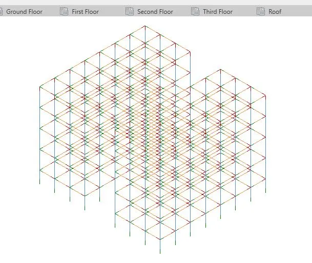
- In 3D view after making beams and columns red line will show that is analytical, which can be off by pressing vg and select custom and select annotation and off the analytical
RESULT :
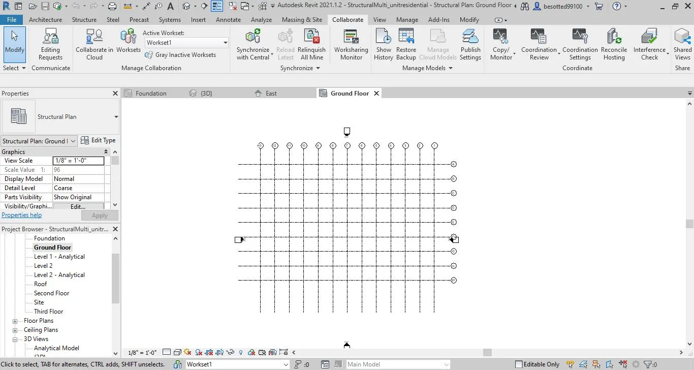
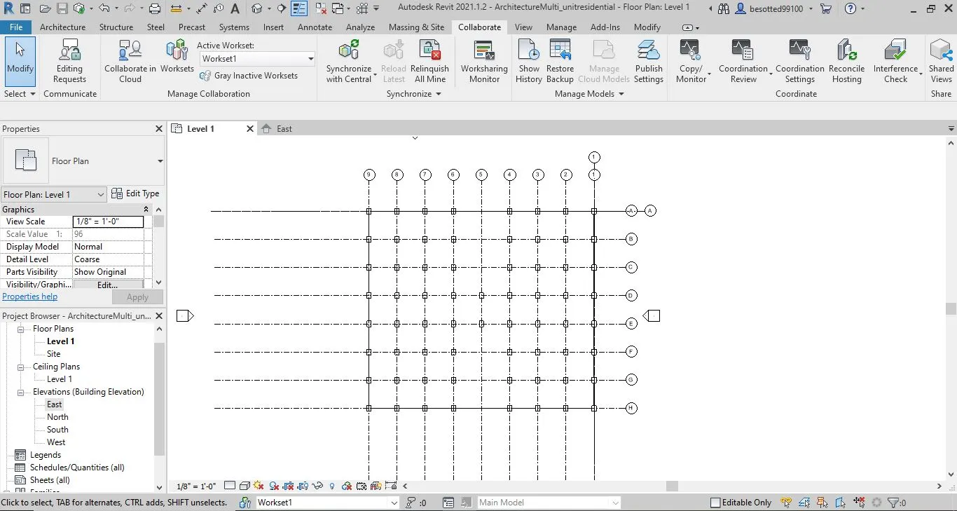
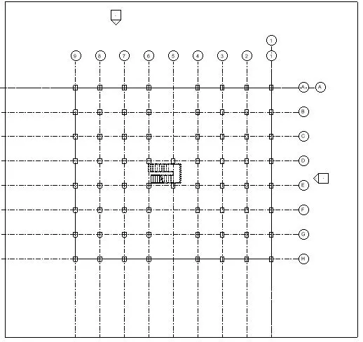
Created Grids
& also made the file as central file
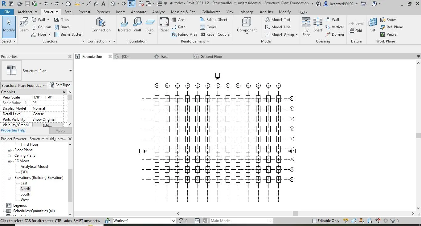
Created isolated footing
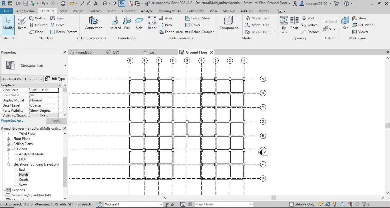
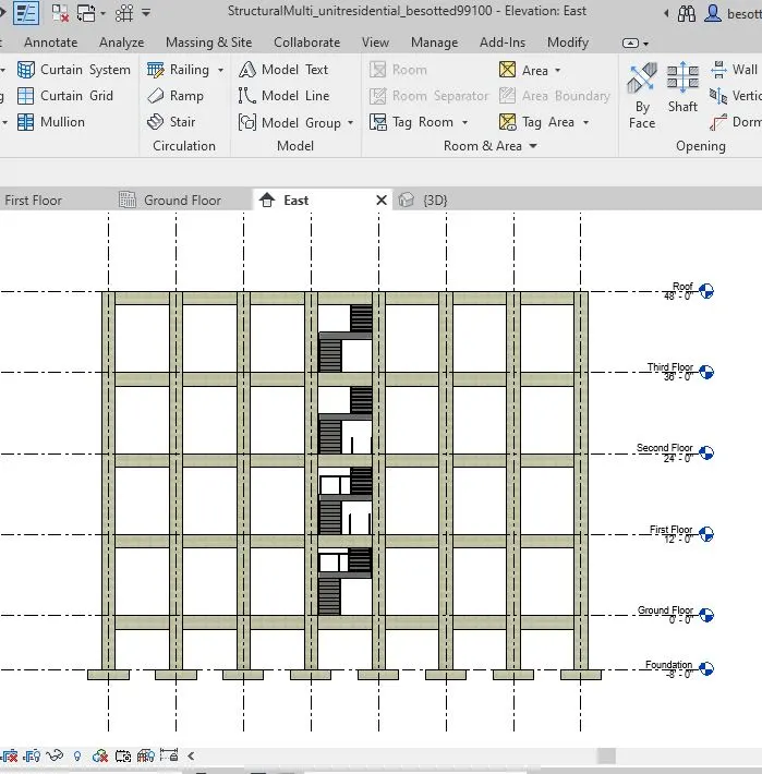
Columns and beams network
Created Floors at every levels
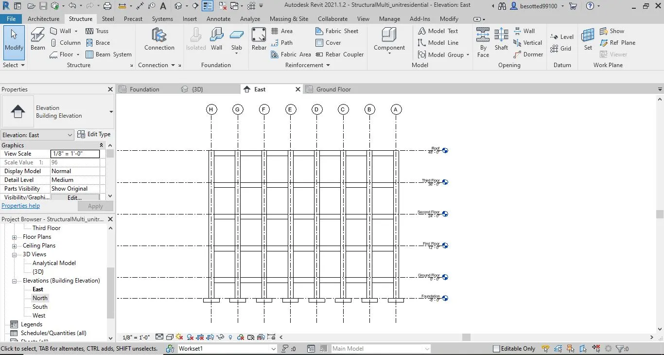
3D view
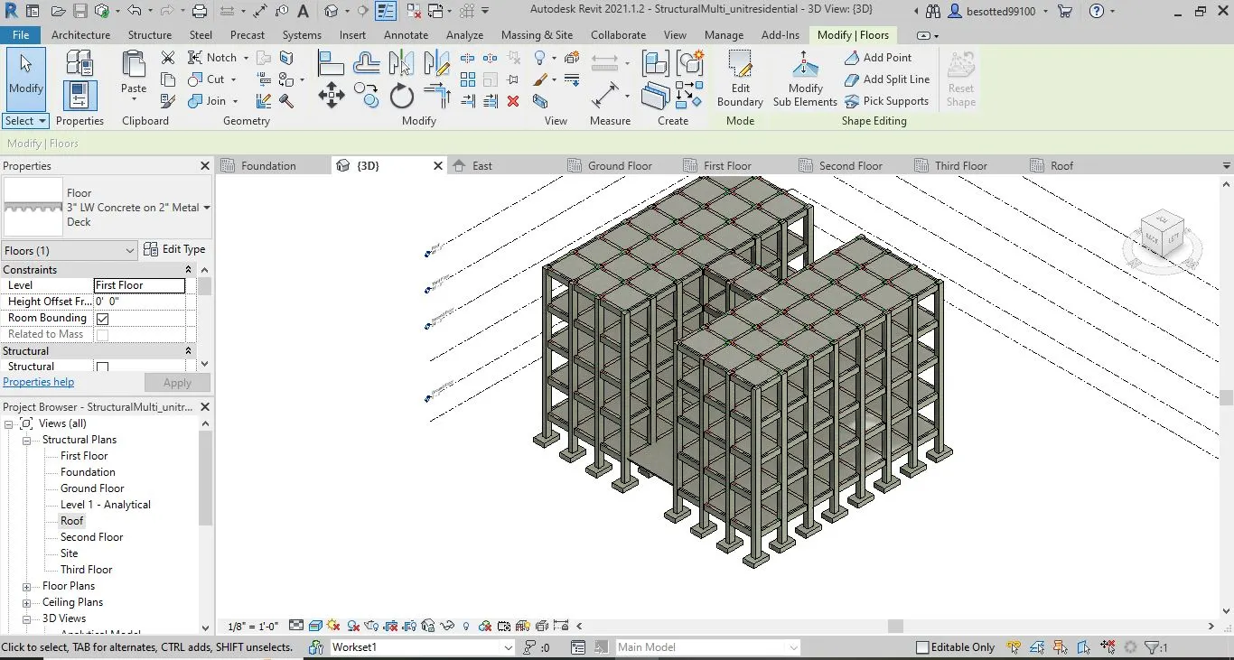
Shaft openings
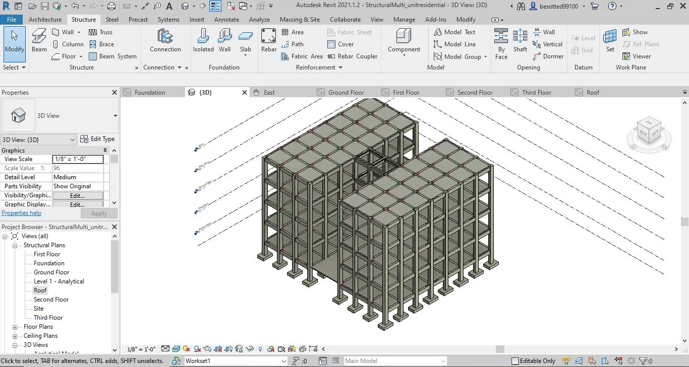
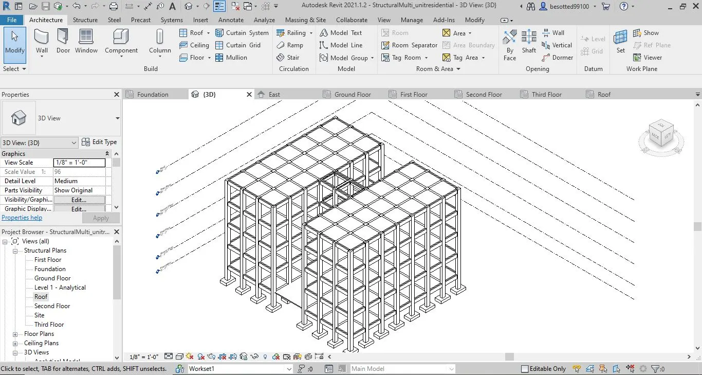
Analytical views
4) Using the architectural model, include the following components based on the type of structure selected
a. Wall Layout with appropriate material and finishing
b. Exterior façade with fancy finish
c. Interior partition walls to size rooms
d. Components to add details to a room ( Desk, Chair, Lighting, Plumbing fixtures)
e. Add components such as stairs Elevators
f. Have at-least one side of the building with curtain walls and glass panels
g. Include interior and exterior lighting fixtures
h. Place proper topographic components from outside ( Trees, Parking, Plants) to add details to the model
ANS :
AIM : Using the architectural model, including various components based on the type of structure selected. Proper designing of Architectural model with all interior and exterior components.
TOOL USED :
Walls
Material
Partition wall
Components as desk, chair lights etc.
Stair
Ceiling
Roof
Windows
Doors
Railing
PROCEDURE :
- Open Revit from the desktop
- Open new Architecture template
- Using Level tool add appropriate levels in the model
- Using Grid tool add Grids to the Ground Floor
- Using Manage tool add specify coordinates at a point 0
- Again using manage tool, click position than relocate project & intersect the architecture & structure grids
- Using Collaborate tool make the structure file as a central file
- Ground floor has no walls so it for parking
- In first floor plan view using architecture tool, than draw outer walls (generic wall 8")
- In first floor plan view using architecture tool, than draw partition walls (generic- brick wall 4")
- Select architecture, add doors (Doors_ExtDbl_w-Glazing_Bars_4) as shown in the model
- Select architecture, add doors (Doors_IntSgl_3) as shown in the model
- Select architecture, add Windows (Windows_Dbl_w-Glazing_Bars_and_1Fixed) as shown in the model
- Select architecture, add Windows () as shown in the model
- Select architecture, add components (like bed, table, chair, sofa, shelves, water closet, bathtub) families as shown in the model
- Select architecture, add components (like trees, street lamps, parking in ground floor) families as shown in the model.
- Select the First Floor plan and select floor architecture and add balcony to one of the bedroom
- Than select architecture, add railing (sketch railing) with pick line option
- Select all the elements from the plan view, than filter option by checking only railing and balcony floor
- Select copy, than paste on the selected levels (second and third)
- Add stairs in the shaft opening done in structure file
RESULT :
Created grids in architecture file
& make the architecture file as central file
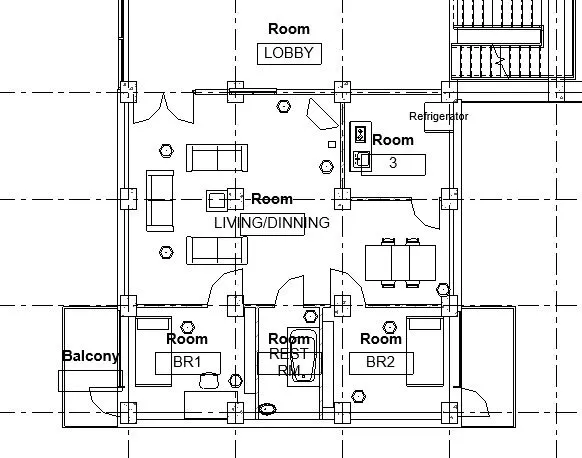
Drawn the 2BHK Flat
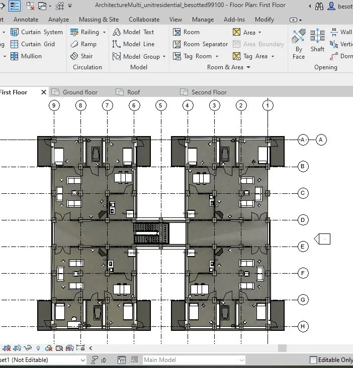
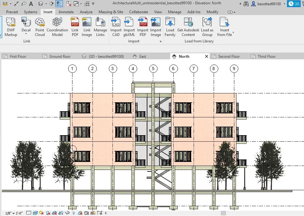
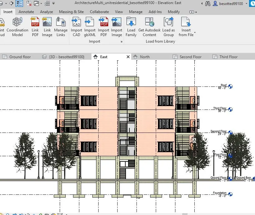
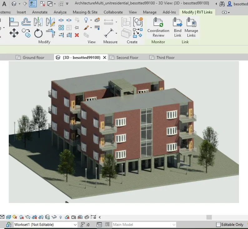
Drawn the 4- unit Residential building
Created Staircase
Staircase elevation view
Elevation view
3D render view
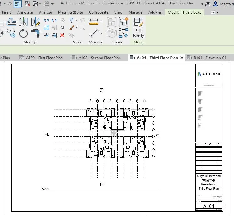
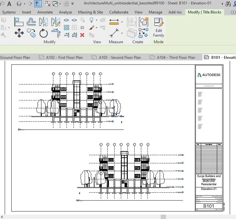
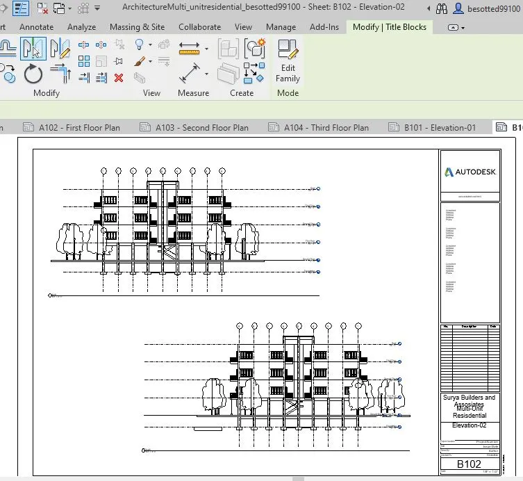
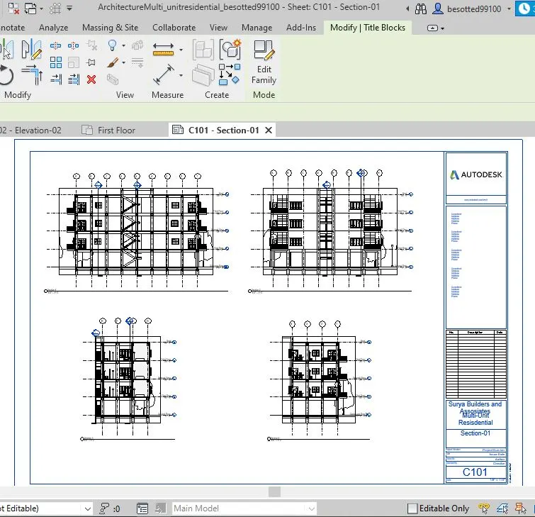
5) Provide a set of drawings in an architectural and structural model to list the following details with categories and appropriate sheet templates included
a. Floor Plans with Annotations
b. Elevations
c. Sections
ANS -
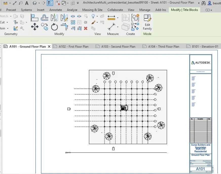
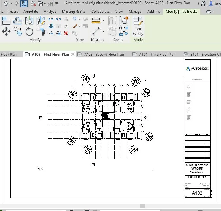
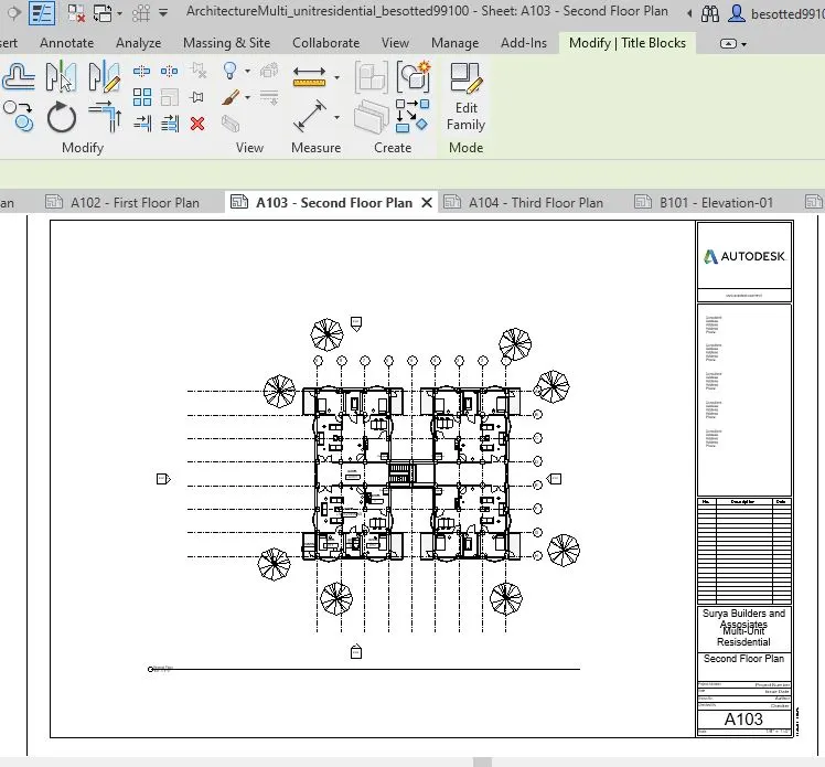
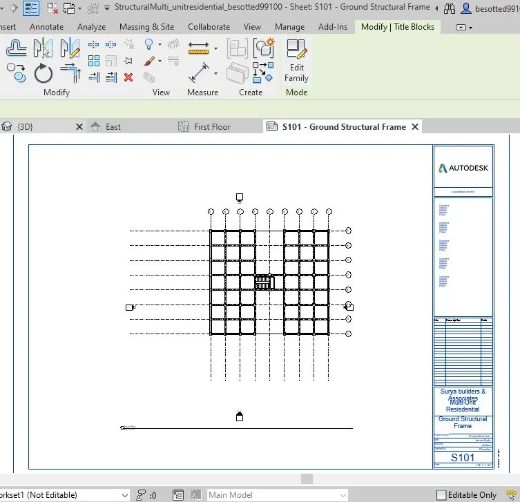
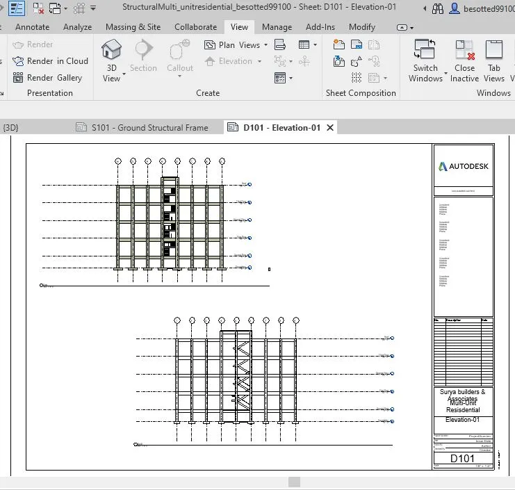
AIM : To create sheet templates for architectural and structural model
TOOL USED :
Sheets
Edit sheets
PROCEDURE :
- Select the view tab and select sheet and load it from the family
- Double click and edit the sheet and load it in the project
- Drag the plans , elevations, section in the sheet and rename the sheet and drawing number and name as per the requirement and save it
RESULT :
6) Using the Rendering settings, Render images of the 3D model produced and include the rendered images to the drawing sheets
a. Rendering from interior rooms
b. Rendering from out showing topographic features
c. Rendering through structural framing
ANS -
AIM :
TOOL USED :
Render
PROCEDURE :
- Select view, add in 3D view click camera
- Put the camera in interior, exterior & slide the mouse for the full view
- Than these views are save in 3D in property browser
- Select the 3D images of the interior rooms, exterior and structural framing and select the render and do the rendering
- Select the properties like exterior sun and artificial setting, or artificial setting, clouds etc.
RESULT :
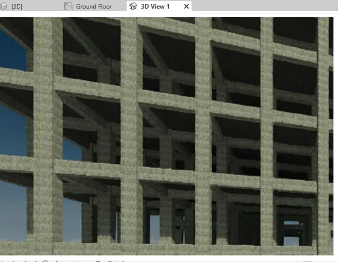
Column and beams render view
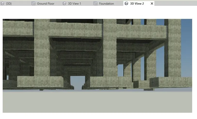
Isolated Footing render View
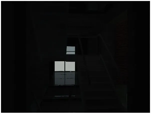
Staircase & Bedroom 1
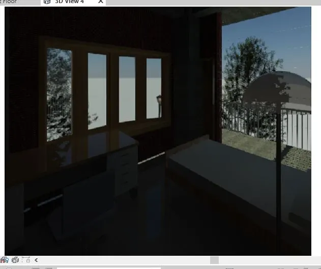
Living room render view
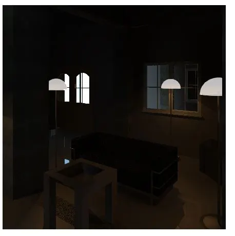
Dinning room render view
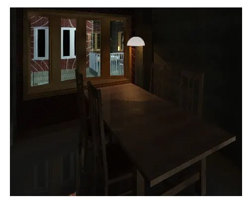
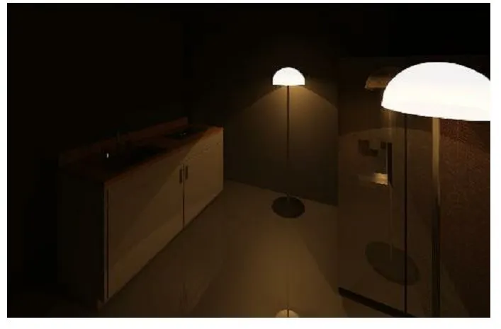
Kitchen render view
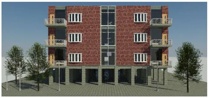
3D render view of Multi-unit residential building
7) Print the set of drawing sheets created and submit the drawings from the architecture and structure model
ANS -
AIM :
TOOL USED :
Setup page
Select the plotter
PROCEDURE :
- Select the views and click print option
- Or Go to sheets created and press ctrl+p. Print dialog box will appear.
- Adjust the setting of the page and print the drawing sheets
RESULT :
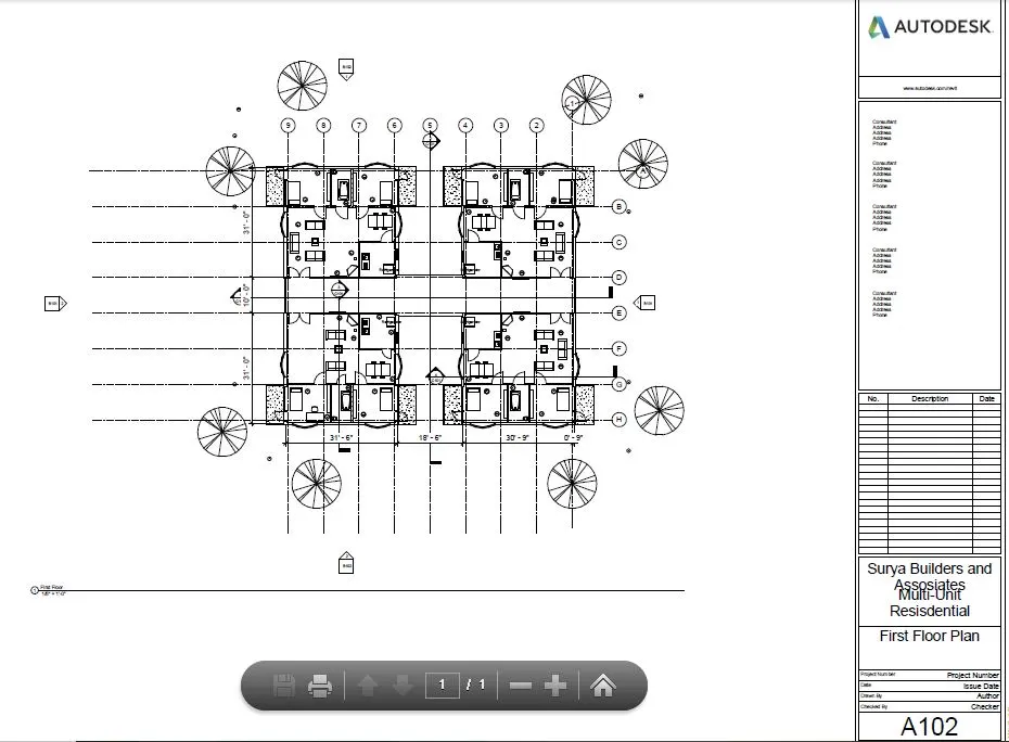
Open sheet A102
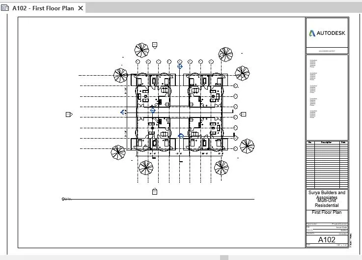
Press Ctrl+P . A dialog box will appear & change setting, then click OK
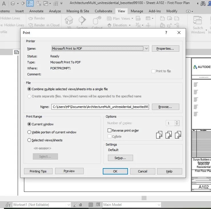
Save the sheet A102 if you don't have printer now
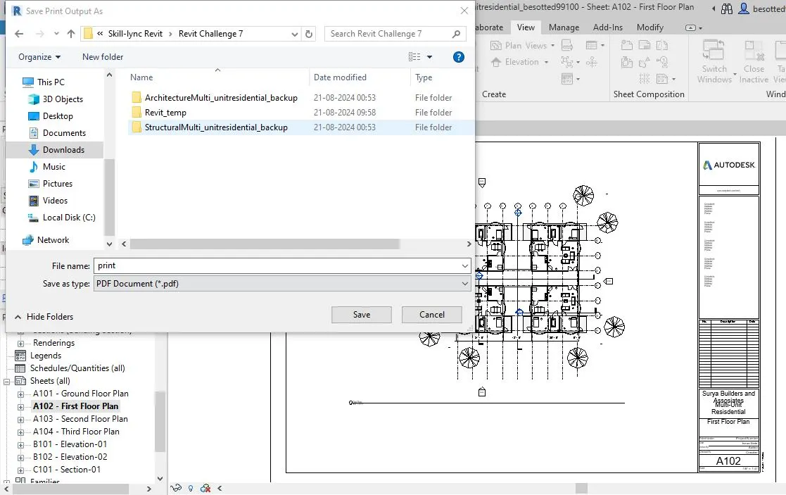
In the PDF the sheet A102 is saved and you print any time