Creating Architectural and Structural model with 3D rendering using REVIT
1.Select the type of structure you want to build from one of the three below:
a. Multi-Unit Residential Apartment
b. Office Buildings
c. School
Answer :- I have selected school building.
2) Assume reasonable assumptions for geographic and location details for your project modeling. Based on assumptions and type of structure selected identify the modeling requirements from NBC.
AIM:-Assume reasonable assumptions for geographic and location details for your project modeling
Procedure:-
Step 1:
- Open Revit
- Open New REVIT File and save it as School building structural.

Step 2:
- Go to Manage Tab and go to Project location Tab
- Click on the location to set the location.
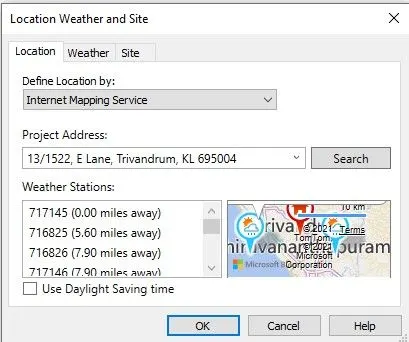
- Location is set
Assumptions for geographic and location details for my project are as follows:-
- My building is constructed in plain area (Geography)
- My building is constructed in 13/1522 E Lane,Trivandrum,KL 695604.
The modeling requirements as per NBC
Points to remember while designing a school building
- A master plan should be drawn up for the site as a whole. For this purpose, the services of a good architect should always be taken for the planning of the building. However, teachers and heads of the institution should also try to equip themselves for giving suggestions to architects or planners in order to make the school plant more useful and serviceable.
- The level of the school should be high so that water-logging does not take place in the monsoon season. There should be a good drainage system.
- Always it is advisable to have the buildings of one storey. The second storey can be constructed in the future when future expansion is needed. So any type or design must therefore take note of this possibility of future expansion. So it is desirable that the school plant should be planned.
- The building should be south-facing, so that sunlight can enter the room in the winter and cannot enter directly in the summer. Provision should be made for the free circulation of air, proper light, and a minimum area to accommodate a certain number of school children. The building must be planned with hygienic laws.
- The school building must provide for certain amenities for the student's such as a common room, sanitary conveniences, provision for mid-day meals, refreshments, and in case of girl students retiring rooms with necessary facilities, accommodation for teachers with a common room available for them where they can meet one another, a reading room and a library; a visitors' room, a room for the headmaster, an office room and a well-planned and equipped science laboratory to stimulate greater interest in science. But the planning and designing should be scientific and modem. The construction of all types of rooms in the building must be determined not by fancy
but by utility. - Adequate space must be provided with classrooms, special rooms, school halls, staff room, office room, pupils' common room, library, and reading room in every secondary school. The classroom should have 600 Sq. Ft floor area (30' x 20'). The height of each room must be more than 15 feet.
- Efforts should be made to have school buildings with a graceful look. The surroundings of the school building should be attractive and must provide a stimulating environment for children to study and conduct co-curricular activities more effectively.
3.Using the structural model. include the following components based on the type of structure selected
a. Foundation — Isolated / Wall/Matt Foundation
b. Columns
c. Beams Connected to Columns
d. Roof Framing/ Truss
e. Floor / Decks
f. Floor Openings for Elevators and Stairs.
Answer :-
Aim :- To draw the structural model of school building.
Procedure :
Step 1
- Click on windows start
- In Search bar type > Revit
- Click > Revit 2019
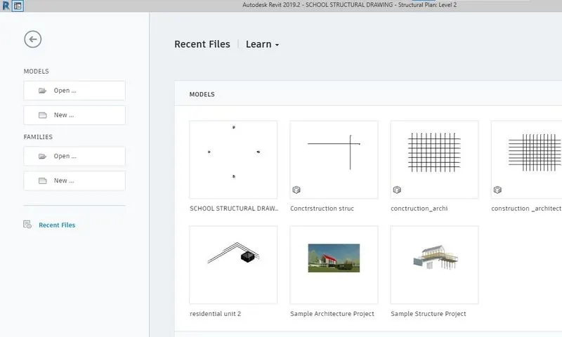
- Once the revit is open, It will shows the following page.
Step 2
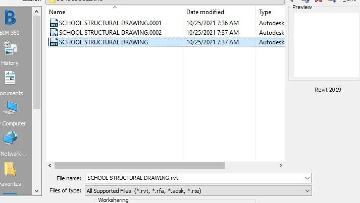
Click on > Open from home page
One dialogue box will open
Cliick School building structural.
Step 3
- Go to Structure panel
- Go to datum tab
- Click > Level
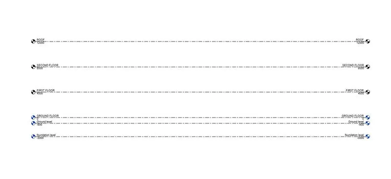
- Provide the levels as per shown below.
Step 5
- Go to Structure panel
- Go to datum tab
- Click > Grid
- Provide the horizontal as well as vertical grids as per shown below.
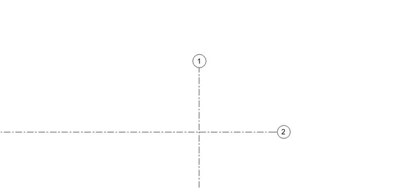
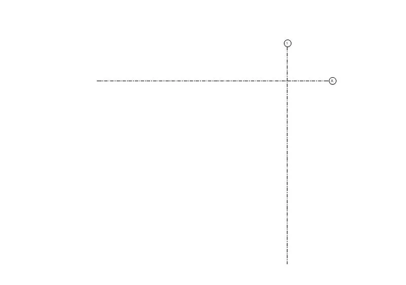
- Rename the horizontal gild 1 as > A
- Rename the vertical grid 2 as > 1
- It will shows the following result.
Step 6
- Go to manage tab
- Go to project location
- Click > Dropdown of coordinates
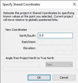
- Click > Specify coordinates at a point
- Select horizontal grid line
- One dialogue box will open
- Set North/ South as > O as per shown below.
- Click > Dropdown of coordinates
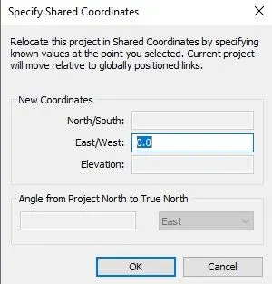
- Click > Specify coordinates at a point
- Select Verticall grid line
- One dialogue box will open
- Set East/ West as > O as per shown below.
Collaborating with Architectural drawing.
Step 1
- Click on > New from home page
- One dialogue box will open
- In that dialogue box > Click on dropdown
- Select template file as > Architectural Template as shown below.
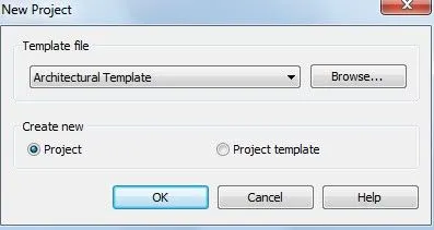
- Click > 0k
Step 2
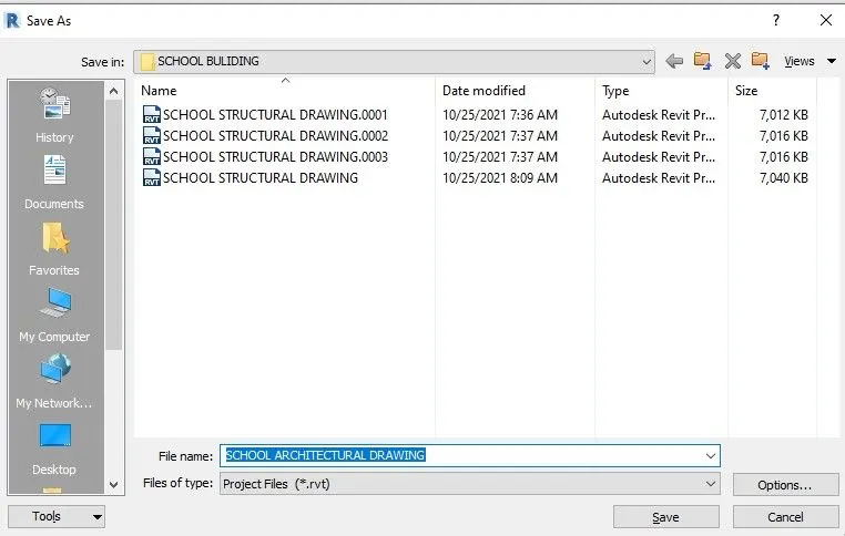
- Click > File
- Click > Save
- One dialogue box will open
- Select file name Architectural Drawing.
Step 3
- Go to architecture panel
- Go to datum tab
- Click > Grid
- Provide the horizontal as well as vertical grids as per shown below.
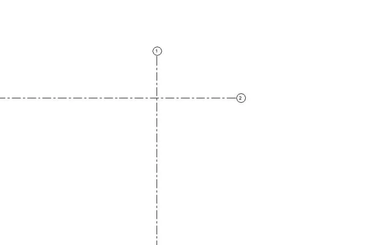
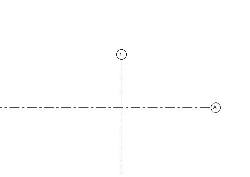
- Rename the horizontal gild 1 as > A
- Rename the vertical grid 2 as > 1
- It will shows the following result
Step 4
- Go to manage tab
- Go to project location
- Click > Dropdown of coordinates
- Click > Specify coordinates at a point
- Select horizontal grid line
- One dialogue box will open
- Set North/ South as > O as per shown below.
- Click > Dropdown of coordinates
- Click > Specify coordinates at a point
- Select Verticall grid line
- One dialogue box will open
- Set East/ West as > O as per shown below.
Step 5
- Go to Collaborate panel
- Go to manage collaboration
- Click > Collaborate
- One dialogue box will open.
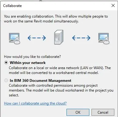
- Select > Within your network
- Click > 0k
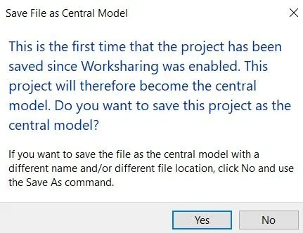
- Go to save option
- One dialogue box will open
- Click > yes
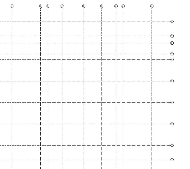
- Draw all the grid lines as per requirements.
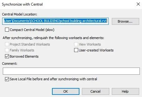
Step 6
- Go to collaborate tab
- Click > Dropdown of synchronize.
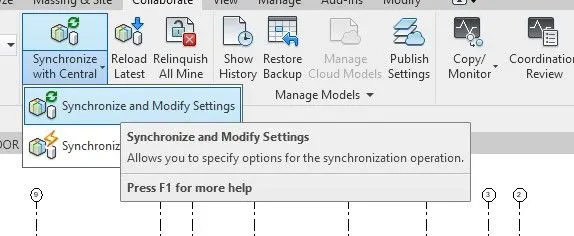
- Select > Synchronize and modify settings
- One dialogue box will open
- Click>Ok
Step 7
- Click on > New from home page
- One dialogue box will open
- In that dialogue box > Structural Drawing.
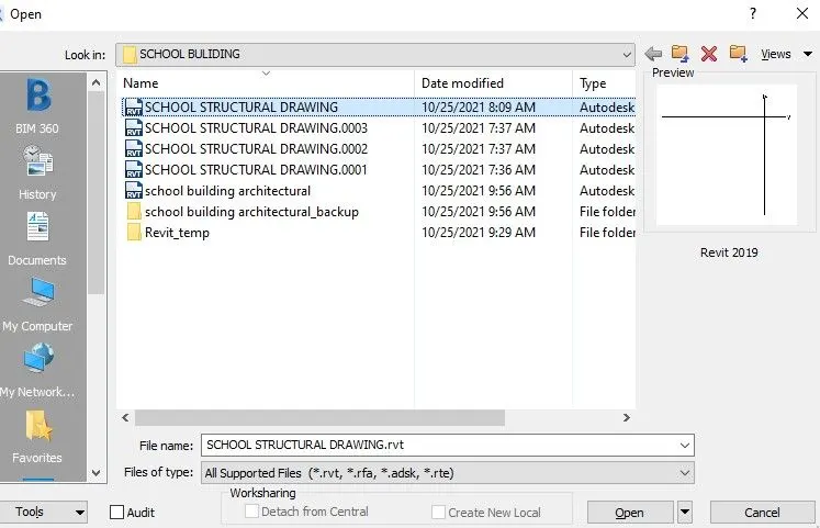
- Click > Open.
Step 8
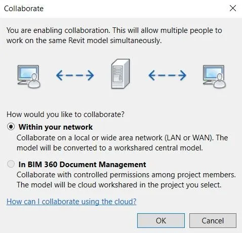
- Go to Collaborate panel
- Go to manage collaboration
- Click > Collaborate
- One dialogue box will open.
Step 9
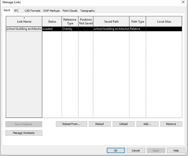
- Go to manage tab
- Click > Manage link
- One dialogue box will open
- Click > Add
- Select > Architectural drawing
- Click > Ok.
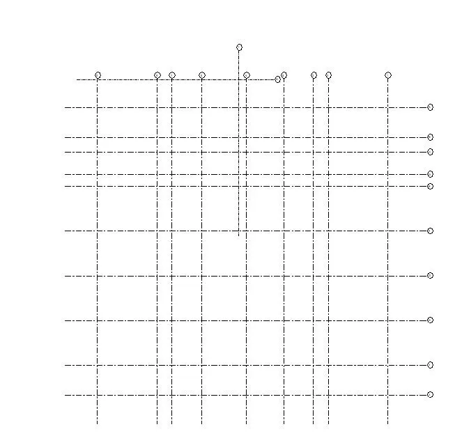
Step 10
- Go to collaborate tab
- Click > Dropdown of copy monitar.
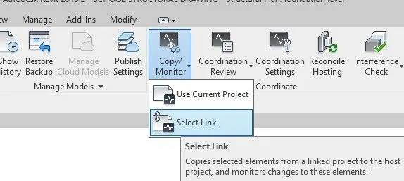
- Select > Select link
- Select the link in the drawing
- Go to modify tab
- Click > Copy
- Select all the grids to copy
- Click > Finish
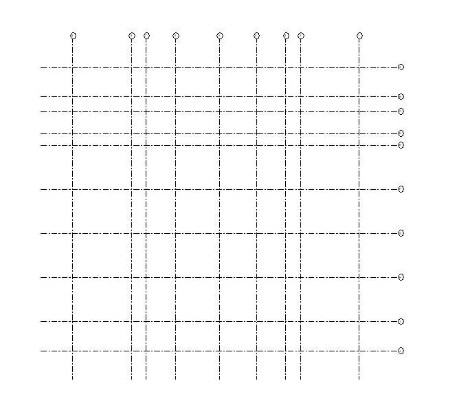
- All the grids from the architectural drawing are copied to the structural drawing
- Go to manage tab
- Click > Manage link.
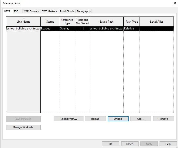
- Click > Unload
- It will shows the following copied grids.
Step 11
- To provide the footing
- Go to structure tab
- Select the Isolated footing
- Provide it as per requirements.
Step 8
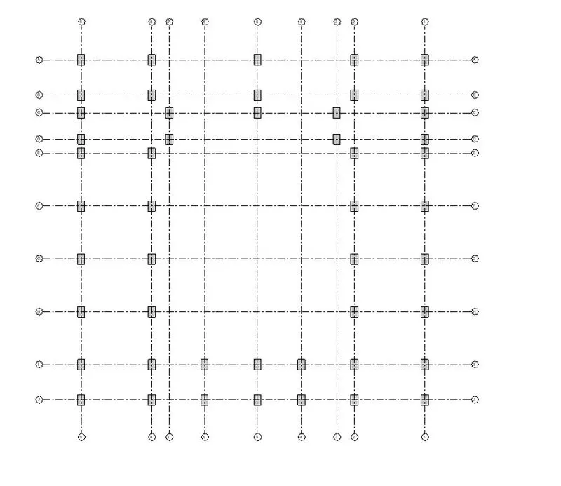
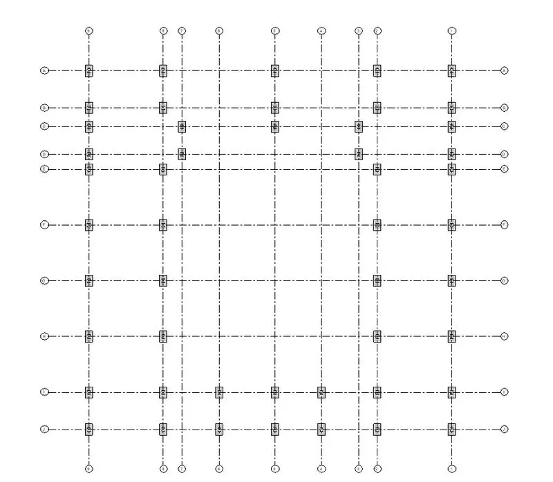
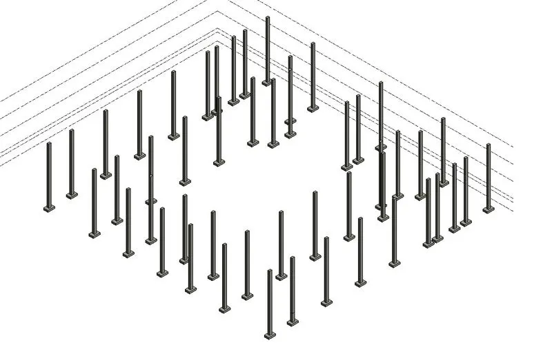
- To provide the columns
- Go to Structure tab
- Select > Column
- Select Proper size of column
- Click > At grids
- Provide the suitable size of column at suitable place.
Step 9
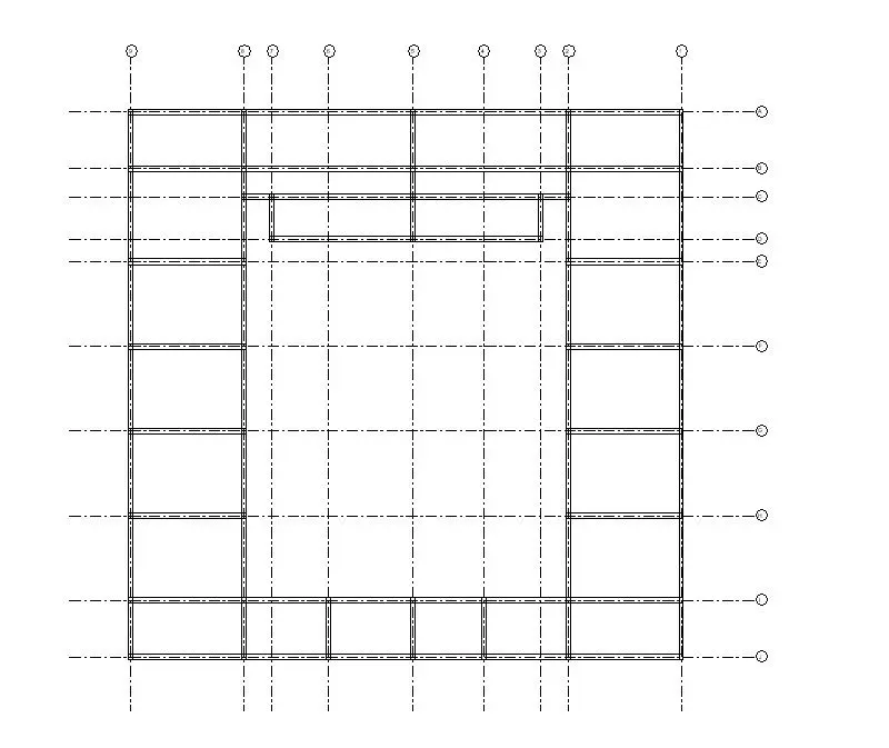
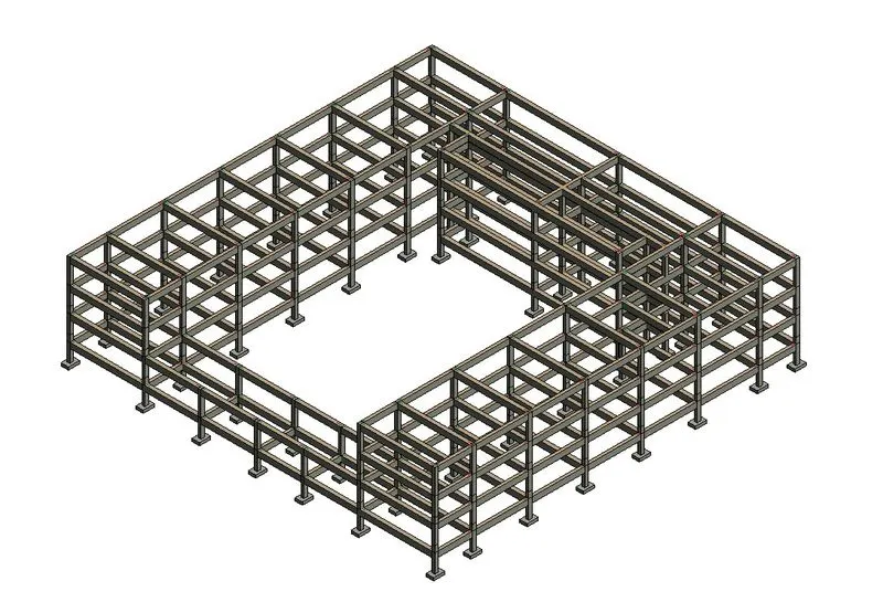
- To provide the Beams
- Go to Structure tab
- Select > Beam
- Select Proper size of Beam
- Provide the suitable size of beam at suitable place.
Step 10
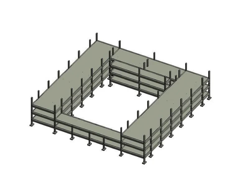
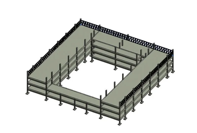
- To provide the Floor
- Go to Structure tab
- Select > Floor
- Select Proper type of Floor
- Select boundary
- Provide the floor at all levels as per shown below.
Step 12
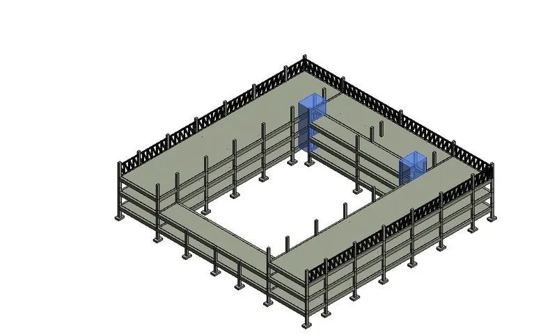
- To provide the Floor opening for stairs
- Go to Structure tab
- Select > Shaft
- Select Top constraint as > Roof level
- Select Base constraint as > Ground Floor
- Provide the floor opening for stairs.
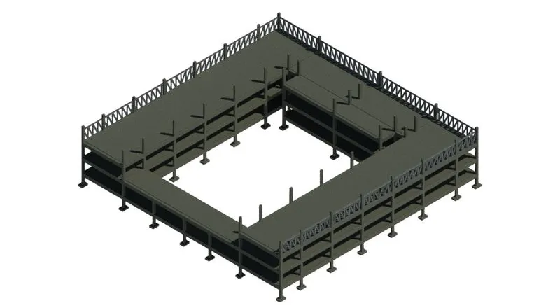
RESULTS:-
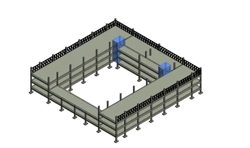
4.Using the architectural model, include the following components based on the type of structure selected.
a. Wall Laput with appropriate material and finishing
b. Exterior facade With fancy finish
c. Interior partition walls to size rooms
d. Components to add details to a room ( Desk, Chair, Lighting, Plumbing fixtures)
e. Add components such as stairs Elevators
f. Have at-least one side of the building with curtain walls and glass panels
g. Include interior and exterior lighting fixtures
h. Place proper topographic components from outside ( Trees, Parking, Plants) to add details to the model.
Aim :- To draw the architectural model of school building.
Procedure :-
Step 1:
- Click on windows start
- In Search bar type > Revit
- Click > Revit 2019
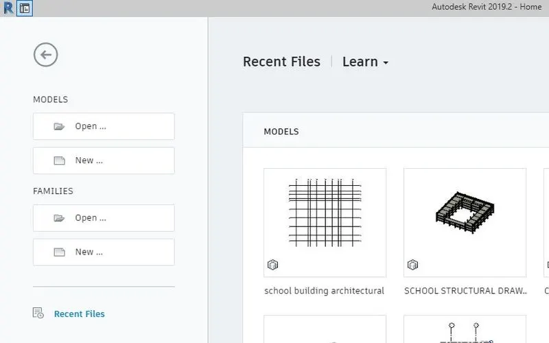
- Once the revit is open, It will shows the following page.
Step 2:
- To provide wall layout with appropriate material and fancy finish
- Go to Architect tab
- Click > Wall
- Select wall type
- Edit wall type as per requirement
- Provide wall to required levels.
Step 8
- To provide Partition
- Go to Architect tab
- Click > Wall
- Select wall type
- Edit wall type as per requirement
- Provide wall to required levels.
STEP 9
- To provide details to building
- Go to Insert tab
- Click > Load family
- Select the family which is required
- Go to properties browser
- From that select the element
- Provide the elements at required position
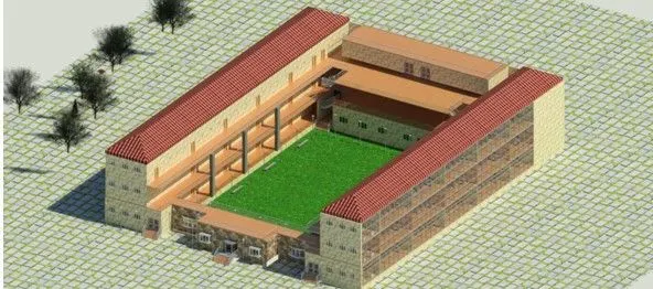
- It will shows the following result.
RESULT:-
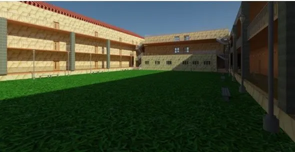
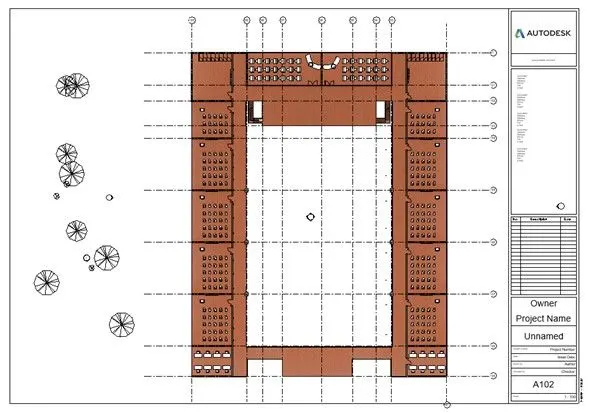
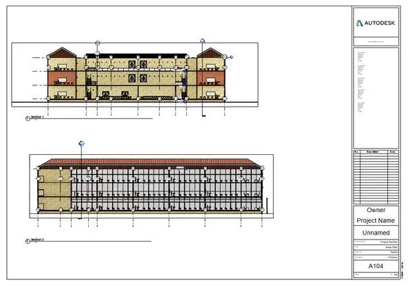
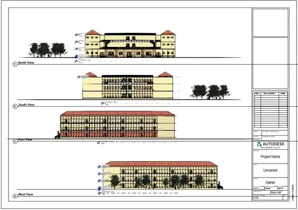
5.Provide a set of drawings in an architectural and structural model to list the following details with categories and appropriate sheet templates included,
a. Floor Plans with Annotations
b. Elevations
c. Sections
Aim :- To create the sheet template from the view tab and to add the various view in it.
Procedure :
Step 1:-
- Click on windows start
- In Search bar type > Revit
- Click > Revit 2019.
- Once the revit is open, It will shows the following page.
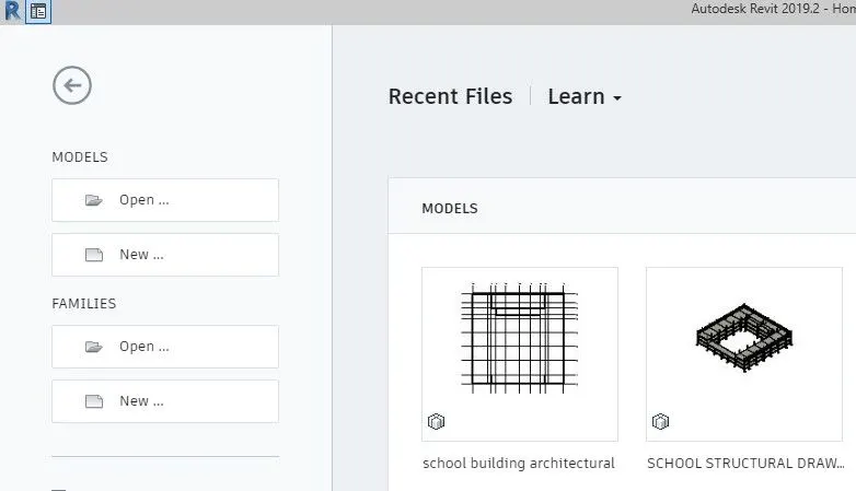
Step 2:-
- Click On > Open
- Open file > School Architectural Drawing
- Click > Open
- The file is opened.
Step 3:-
- Go to properties browser
- Click > Ground floor view
- Go to ground floor window
- Go to view tab
- Click > Section
- Provide the section 1 line as per shown below.
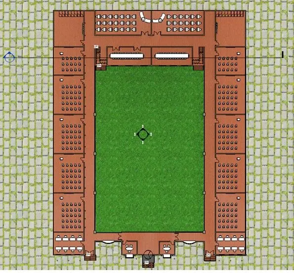
- Similarly provide another section line as per shown below.
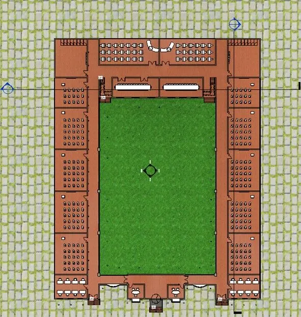
- Go to properties browser
- Click > Section
- Double click > Section 1
- Section 1 Window will open
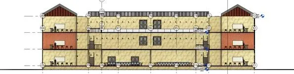
- Go to properties browser
- Click > Section
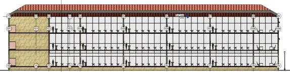
- Double click > Section 2
- Section 2 Window will open.
Step 4:-
- Go to insert tab
- Click on > Load family
- One dialogue box will open
- Select >Titleblocks
- Select > AO sheet
- Click > open
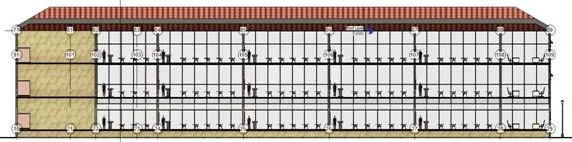
- Go to properties browser
- Click > *Sheet > enter
- The following sheet will open.
Step 5:-
- To add the view parameters on the sheet
- Got to properties browser
- Click > Sheets
- Right clisk on the respective sheet
- Click > Add views
- One dialogue box will open
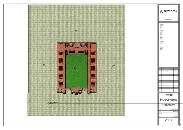
- Select > Ground Floor
- Click > Add view to sheet
- Place in a proper position.
- Similarly place all the required views.
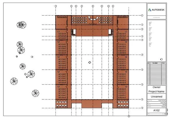
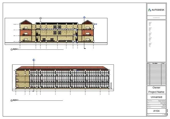
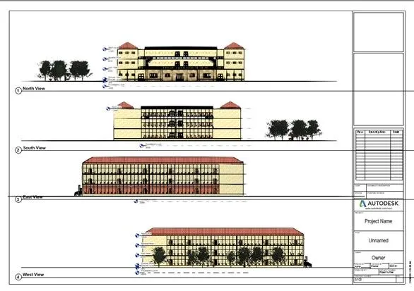
Result:
Floor Views Sheet:
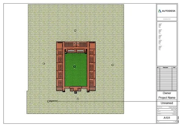
SECTION VIEWS SHEET:
ELEVATION VIEW SHEET:-
6.Using the Rendering settings, Render images of the 3D model produced and hclude the rendered images to the drawing sheets
a. Rendering from interior rooms
b. Rendering from out showing topographic features
c. Rendering through structural framing
Aim :- To render the views and to add the various view in sheets
Procedure :
Step 1
- Click on windows start
- In Search bar type > Revit
- Click > Revit 2019
- Once the revit is open, It will shows the following page.
Step 2:
- Click On > Open
- Open file > School Architectural Drawing
- Click > Open
- The file is opened.
Step 3
- To render the view
- Open the window which is to be renderd
- Go to view tab
- Click > Render
- Set the exposure condition
- Save to project by appropriate name
- The rendered image saved.
Step 4:
- Go to insert tab
- Click on > Load family
- One dialogue box will open
- Select > Titleblocks
- Select > AO sheet
- Click > open
- Go to properties browser
- Click > +Sheet > enter
- The following sheet will open.
Step 5
- To add the view parameters on the sheet
- Got to properties browser
- Click > Sheets
- Right clisk on the respective sheet
- Click > Add views
- One dialogue box will open
- Select > Rendered classroom
- Click > Add view to sheet
- Place in a proper position.
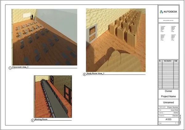
- Similarly provide all the rendering views in the sheet.
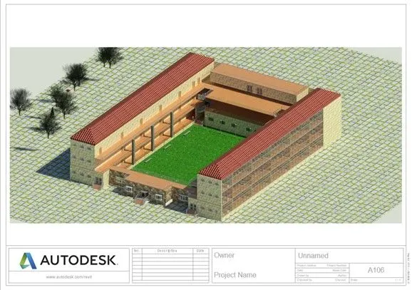
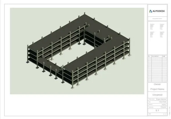
Result:
Rendering sheet of interior room:-
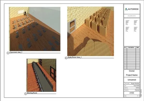
Rendering sheet of topography feature
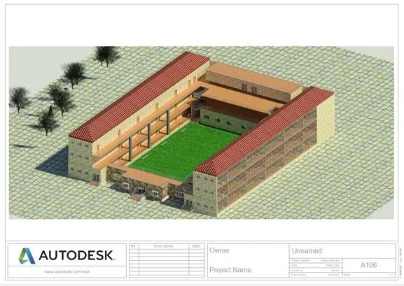
Rendering sheet of structural frame
7) Print the set of drawing sheets created and submit the drawings from the architecture and structure model
Aim: Print the set of drawing sheets created and submit the drawings.
Procedure:
- Click on CTRL+P on the screen.
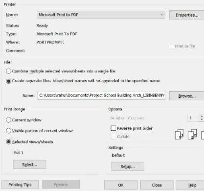
- Click on select Set.
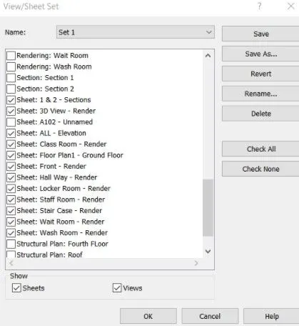
- Select all the sheets needed for print and click OK
- Set the print file name and save it as print to pdf and click SAVE
- The respective documents are submitted as per requirement.