Creating Architectural and Structural model with 3D rendering using REVIT
1) Select the type of structure you want to build from one of the three below:
a. Multi-Unit Residential Apartment
b. Office Buildings
c. School
Aim:
To create a Multi-Unit Residential Apartment using Revit.
Introduction:
To create a Multi-Unit Residential Apartment using Architectural and Structural Elements Using Revit. Also used Special Equipments, Shaft opening, Lift, Architectural Elements and Structural Elements like Column, Beam, Foundation and Floors.
Procedure:
- Create a New Structural Model.
- Select Grid Option.
- Draw grid Lines as you want.
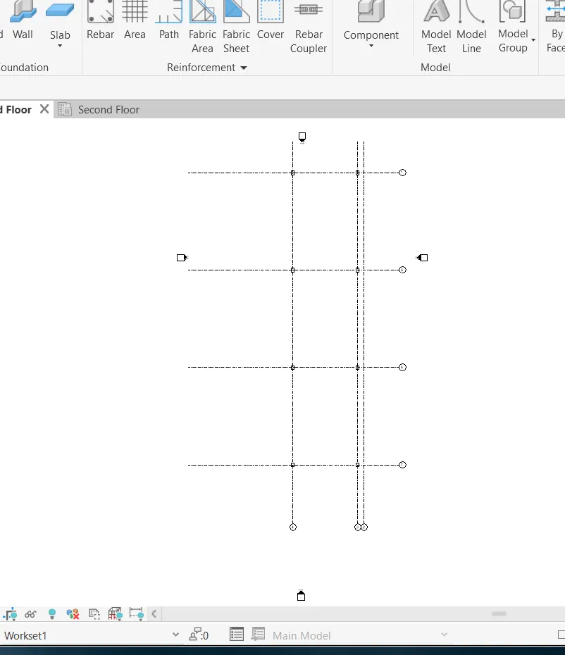
- Select Column in the Structural Toolbar.
- Insert it at the grids.
- Then Select Isolated Footings.
- Place it at the columns.
- Then Select Beams.
- Then connect it to the columns.
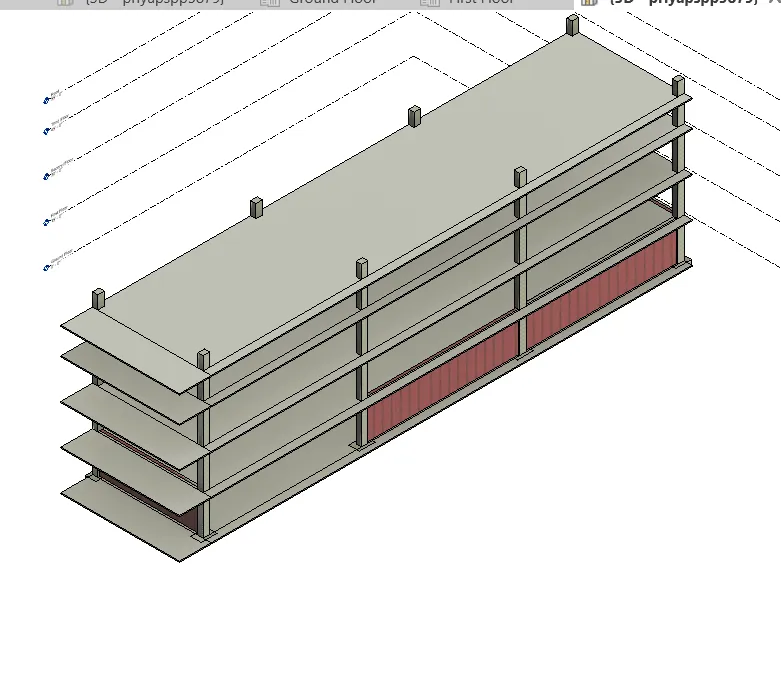
- Then create a structural Floor.
- Then create a structural wall for the ground floor paking area.
- Create a New Architectural Model.
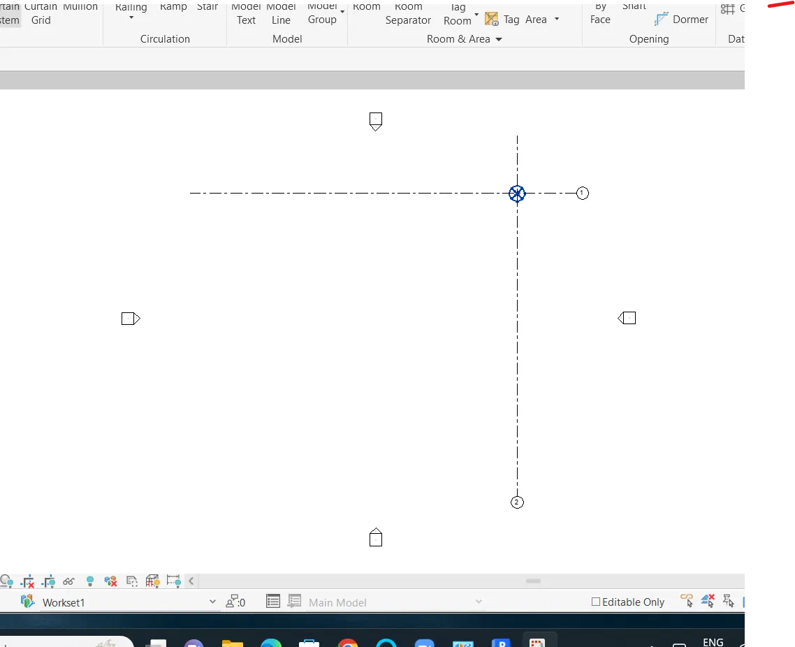
- Select the grids.
- Draw the grid lines.
- And go to Insert tab.
- Link the Structural Revit model which is already created.
- Then use copy monitor and copy the structural model to the architectural model.
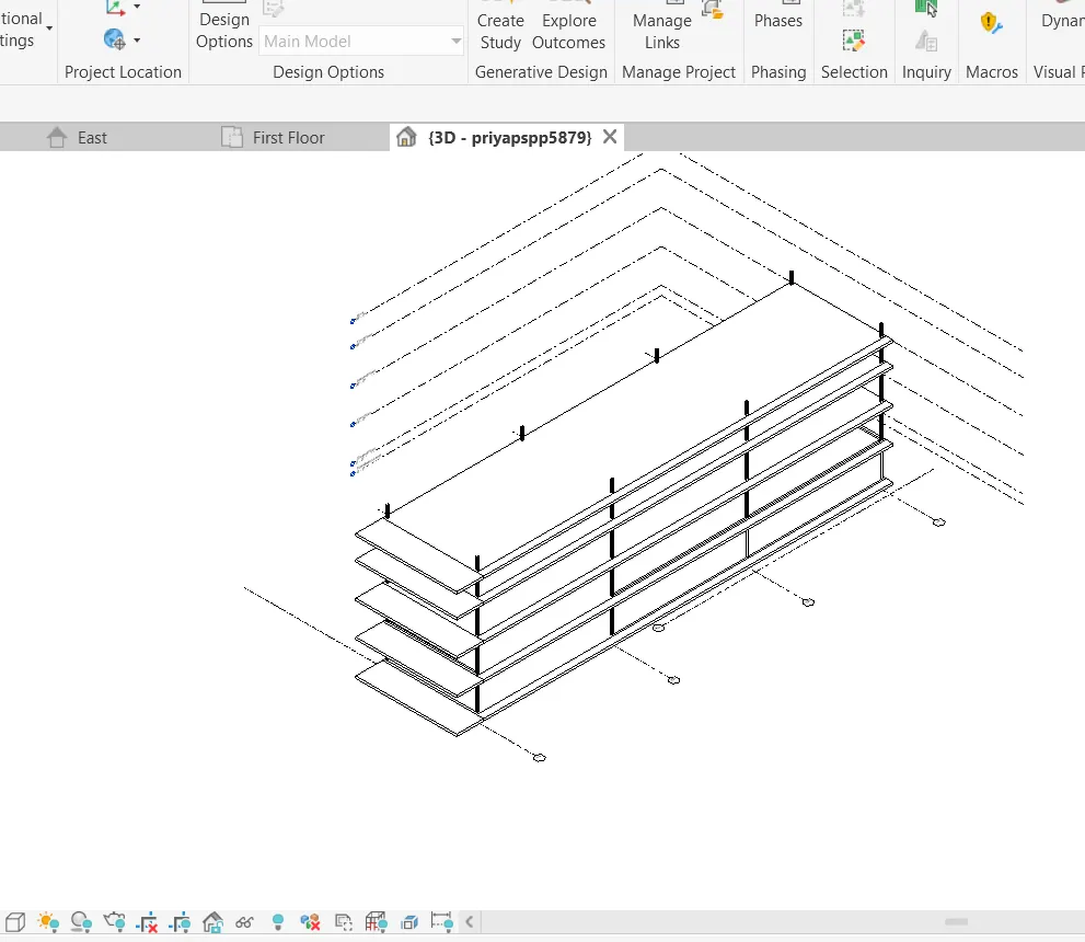
- Then go to the architectural toolbar.
- Select shaft openings.
- Draw the space for the shaft opening in the ground floor.
- Then copy it to the roof floor.
- Then Use Exterial glass for walls.
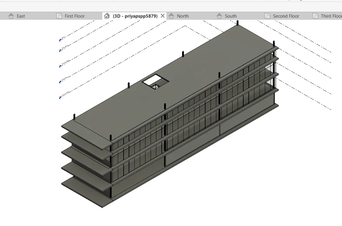
- Then go to Architectural tab and select place a component.
- Then Load family.
- Then select the components like sofa, chair, Dining table, Kithen, Bath tub, Desk, Bed, etc.
- Then select the stair and place it to the ground floor to the roof.
- Then Use Glass panel for the Railings.
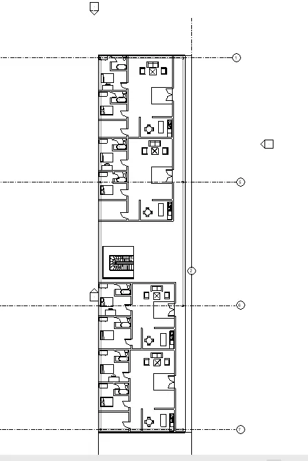
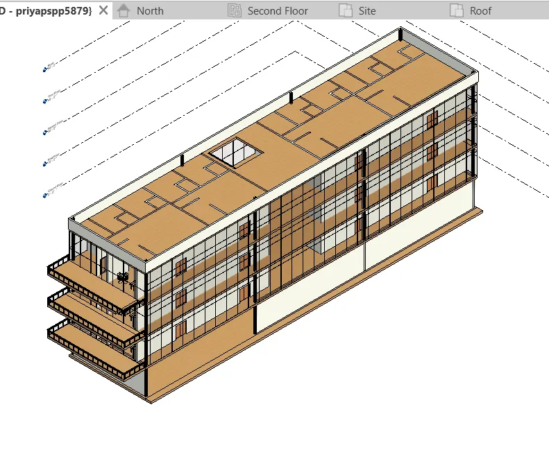
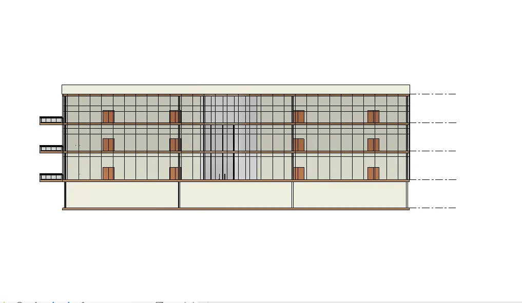
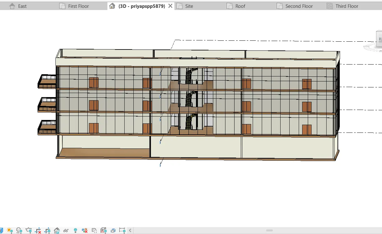
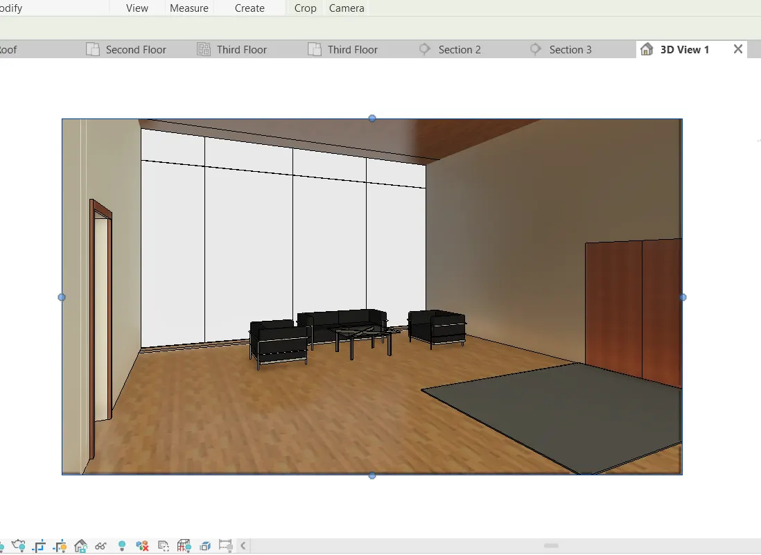
- Living Room
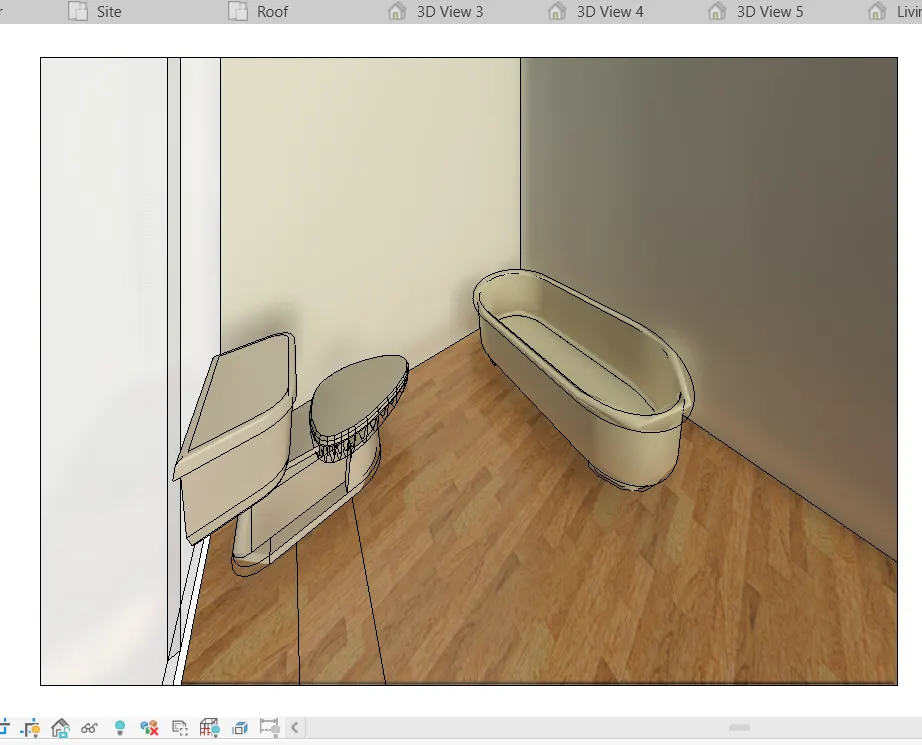
- Rest Room
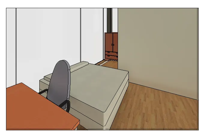
- Bed Room
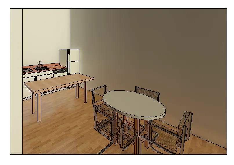
- Kitchen and Dining Room
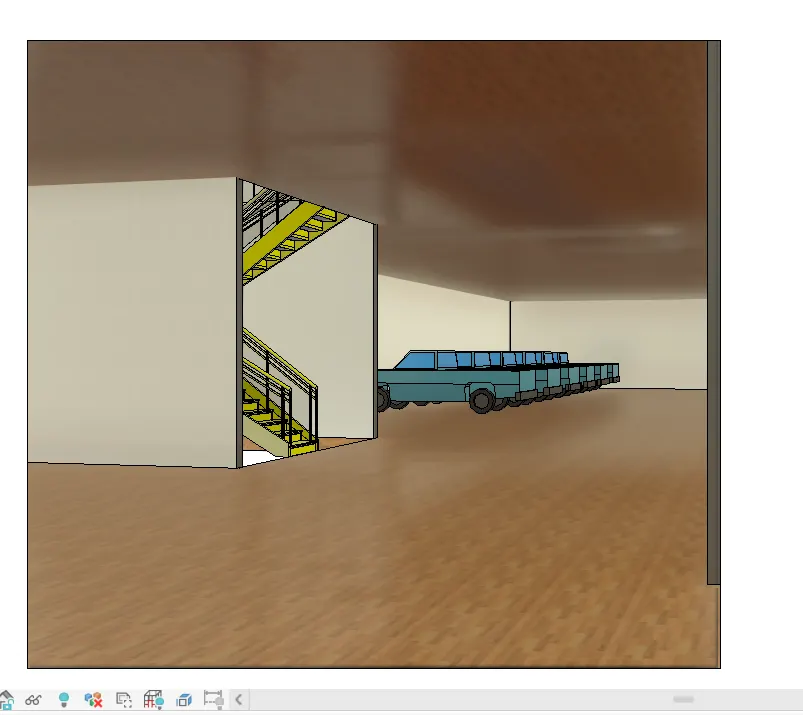
- Ground floor for the parking
- Use the Topography option and draw the topography.
- Then use place a component and place the plantings, Trash can, Street lights.
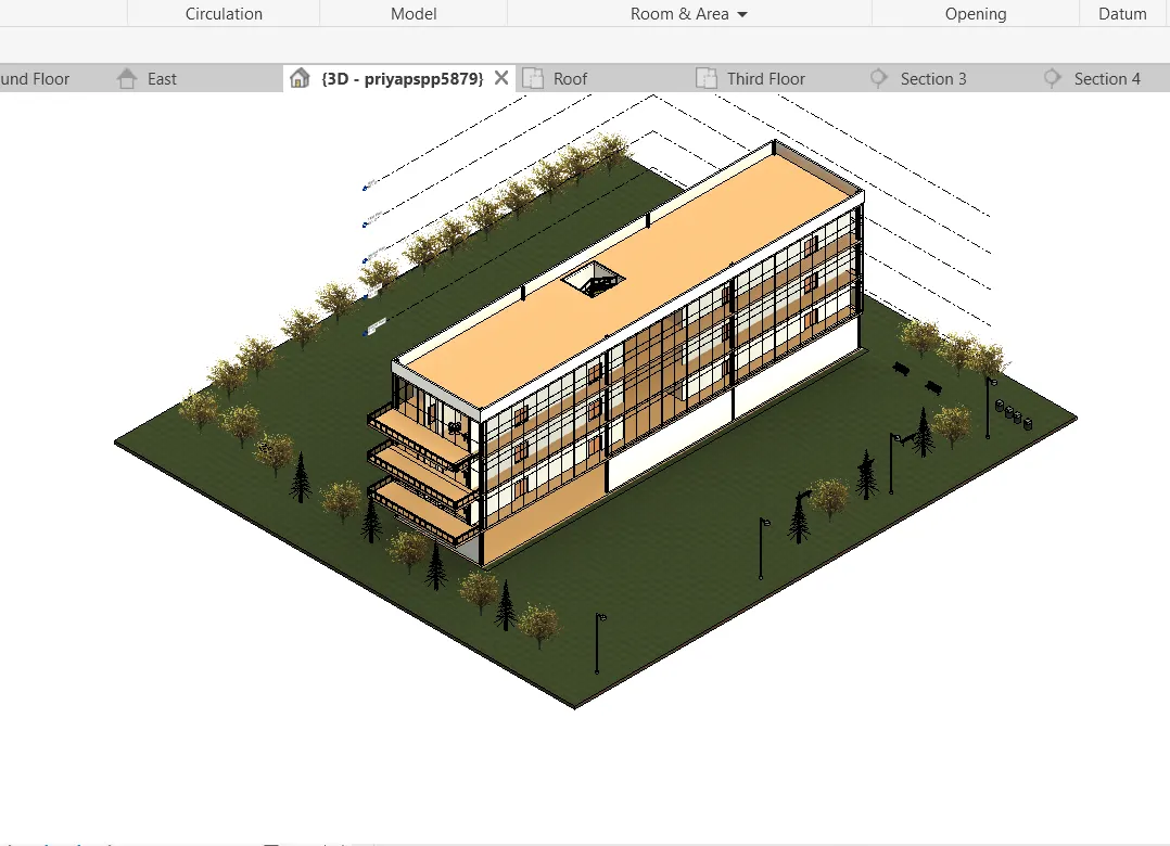
- Then use parking bench for people sitting.
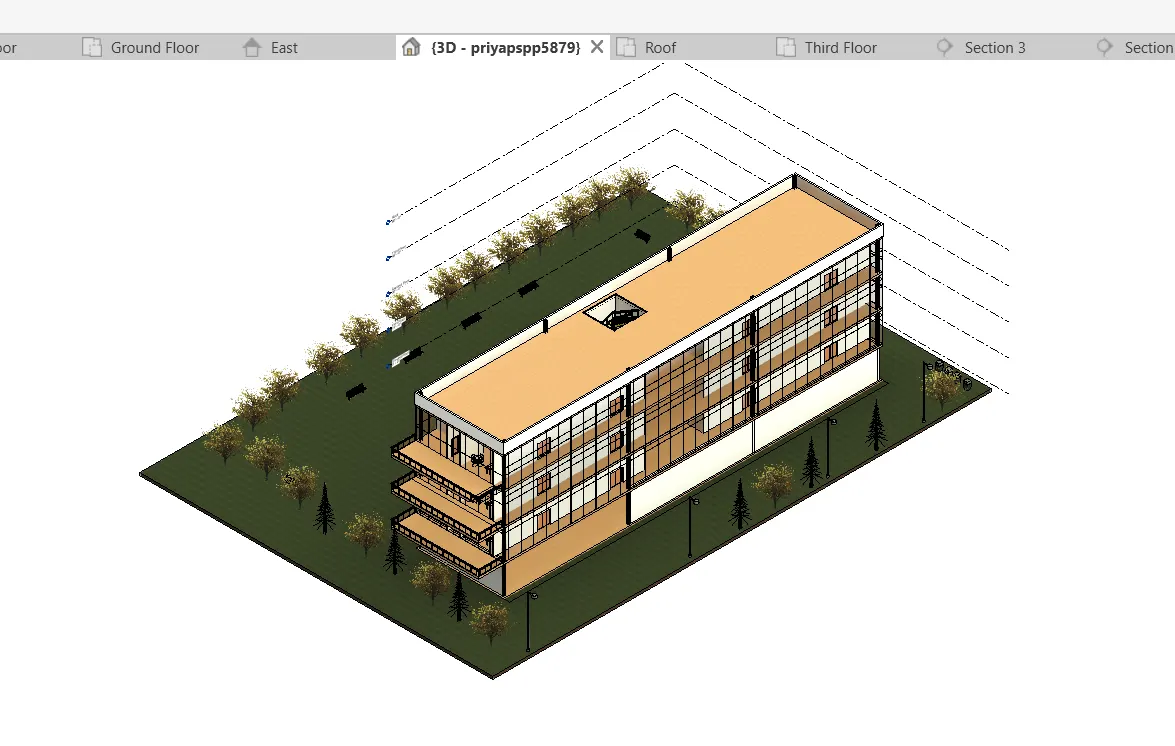
Result:
2) Assume reasonable assumptions for geographic and location details for your project modeling. Based on assumptions and type of structure selected identify the modeling requirements from NBC
Aim:
To create a project information and modeling requirements as per NBC guidelines with assumed geographic and location details.
Introduction:
Assume the Geographic and location details for the Project Information. Then Use NBC guidelines as per the code book 2016 for the modeling requirements for the created Multi-Unit residential Apartment.
Procedure:
- Go to Manage toolbar.
- Select the Project location.
- Set the location for the project (assume).
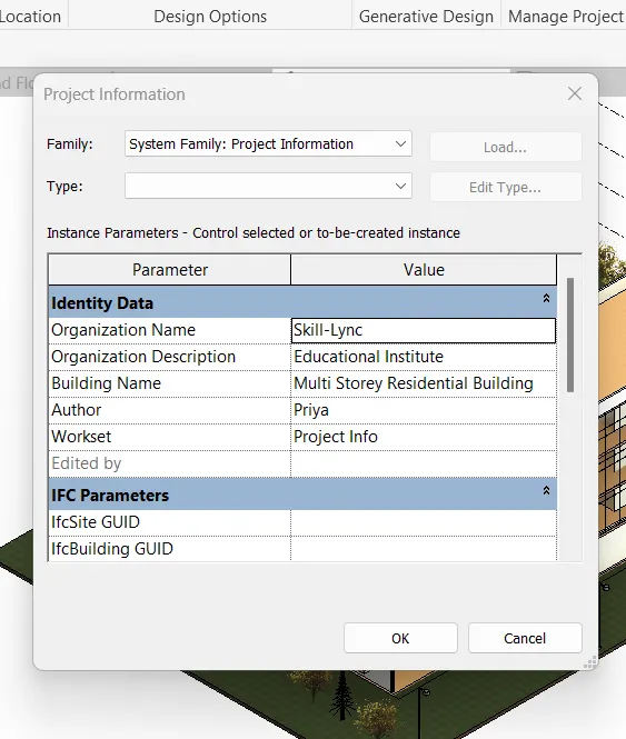
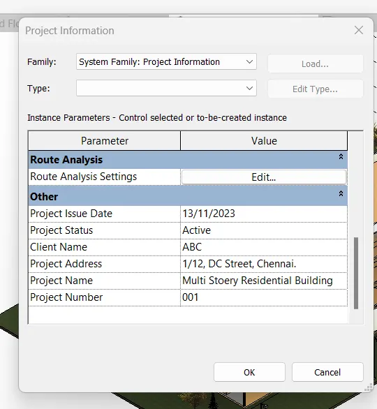
- Then select the project Information.
- Then fill the information for the project as below.
- The building is located at Chennai.
- As per NBC the open space around the building is not less than 3m.
- And the Floor Area Ratio of the building is 3.4ft which is satisfied with the NBC Guidelines.
- The total plot area is 8190sq.ft and the single floor area is 2400sq.ft. Therefore the Floor Ratio area of the building is 3.4ft.
- Then the Height of the floor is 4.5m from the ground level.
3) Using the structural model, include the following components based on the type of structure selected
a. Foundation – Isolated / Wall/Matt Foundation
b. Columns
c. Beams Connected to Columns
d. Roof Framing/ Truss
e. Floor / Decks
f. Floor Openings for Elevators and Stairs
Aim:
To create a structural elements like Foundation, Column, Beam, Floor and wall for the Structural Model.
Introduction:
Go to the structural model and create the structural elements using the structural toolbar.
Procedure:
- Open a structural model.
- Go to structural toolbar.
- Select Grids.
- Draw the grid lines.
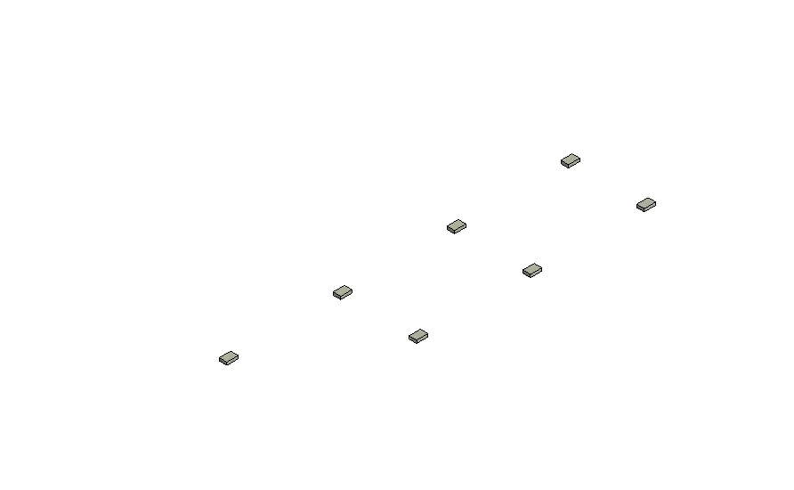
- Then select the Foundation.
- Draw the Foundation at the grids.
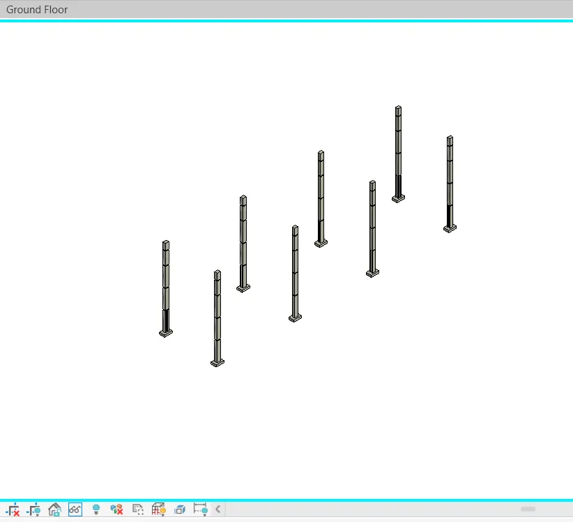
- Then select the Columns.
- And draw the columns at the foundation.
- Then select the columns at the ground level and make the top constraint as Roof.
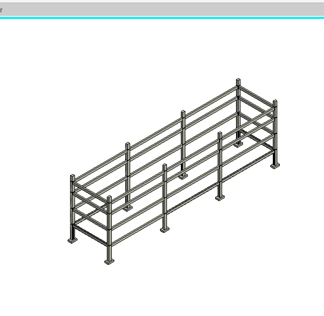
- Then Selec the Beams.
- Then draw the beams connecting the columns.
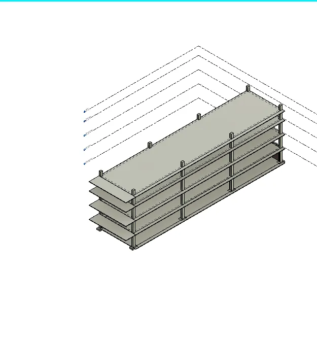
- Then select the structural floor.
- Draw the structural floor.
- In the Architectural tab select the shaft.
- And create the shaft opening for the lift or stair.
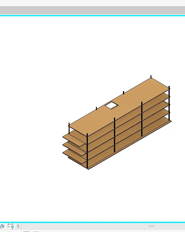
4) Using the architectural model, include the following components based on the type of structure selected
a. Wall Layout with appropriate material and finishing
b. Exterior façade with fancy finish
c. Interior partition walls to size rooms
d. Components to add details to a room ( Desk, Chair, Lighting, Plumbing fixtures)
e. Add components such as stairs Elevators
f. Have at-least one side of the building with curtain walls and glass panels
g. Include interior and exterior lighting fixtures
h. Place proper topographic components from outside ( Trees, Parking, Plants) to add details to the model
Aim:
To create a architectural elements in the architectural model.
Introduction:
Create the Architectural elements like Exterior and Interior walls, Desk, chair, Lighting, Plumbing fixtures, stairs, Glass panels, Topographic components,etc. using Architectural Toolbar for the Architectural Model.
Procedure:
- Create a New Architectural Model.
- Go to Architectural wall.
- Use exterior glassing for the Exterior walls.
- And use Basic wall generic 8" for the Interior walls.
- Then create the doors for the Rooms.
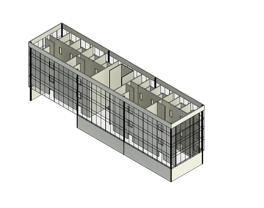
- This is the floor plan for the first floor of the Architectural model.
- Go to Arhcitectrural tab.
- Select place a component and load the family
- Then select and place the Sofa, Chair, Floor lamps and Carpet in the living room.
- Dining table, Kitchen set and Normal Rectangular table for the Kitchen in the Kitchen
- Toilet dommestic, Floor lamp and Bath tub in the Rest room.
- Bed, Wardrobe, Desk and Chair in the Bed room.
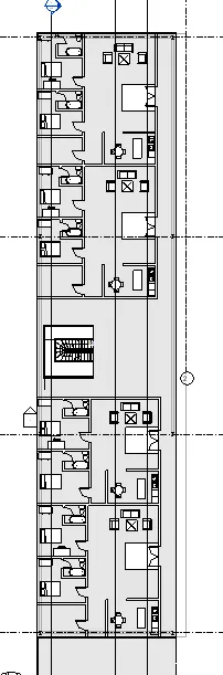
- 3D Model of Bed room.
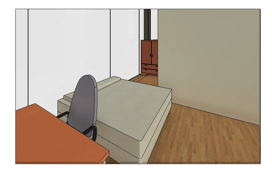
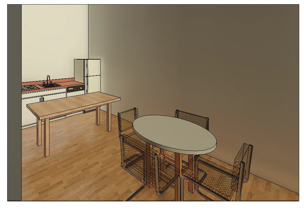
- 3D Model of Kitchen and Dining.
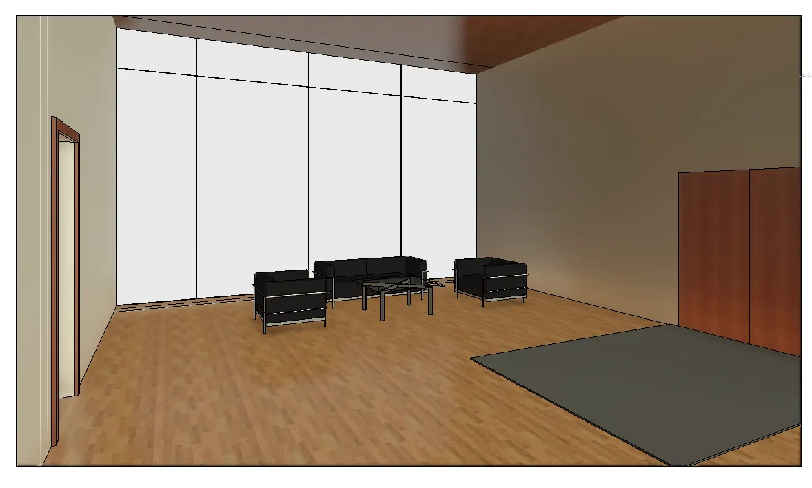
- 3D Model of Living Room.
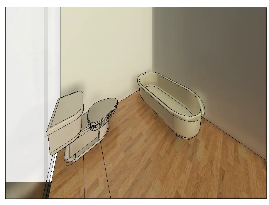
- 3D Model of Rest Room.
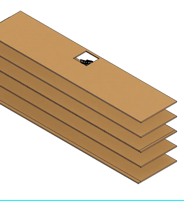
- 3D Model of the Shaft openings.
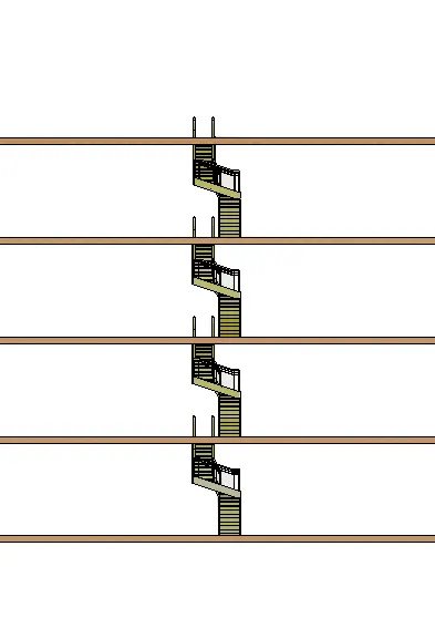
- 3D Model of the Stairs.
- Go to the Manage and Site tab
- Selec the toposolid.
- And draw the topographic View.
- Then place a component Plantings, Street Lights, Parking Bench.
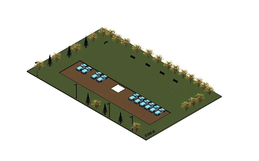
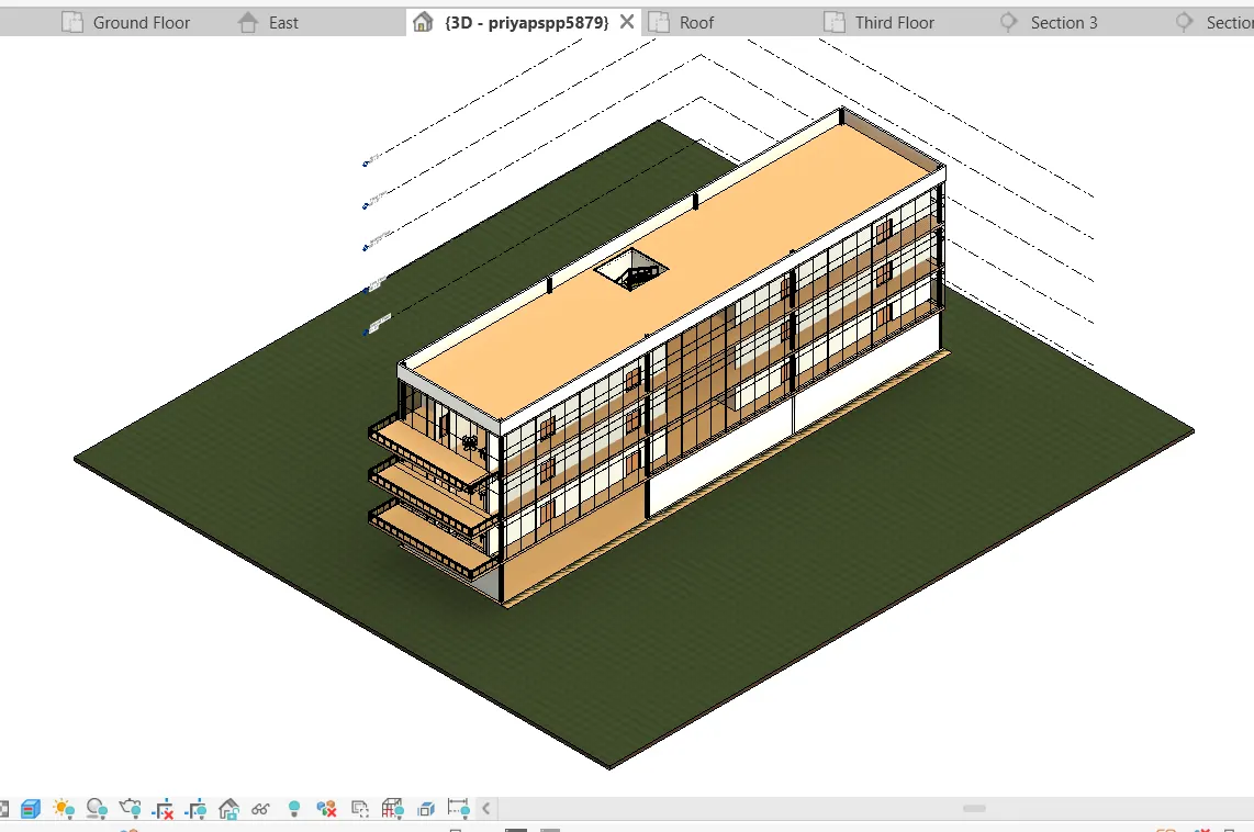
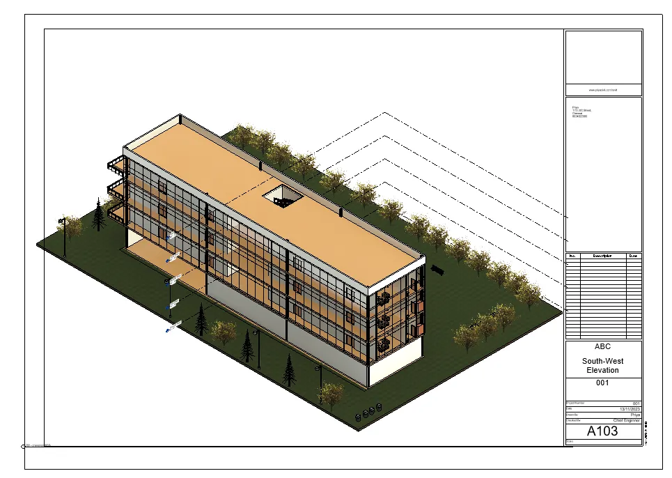
- 3D Model of the Architectural building with the topographic components.
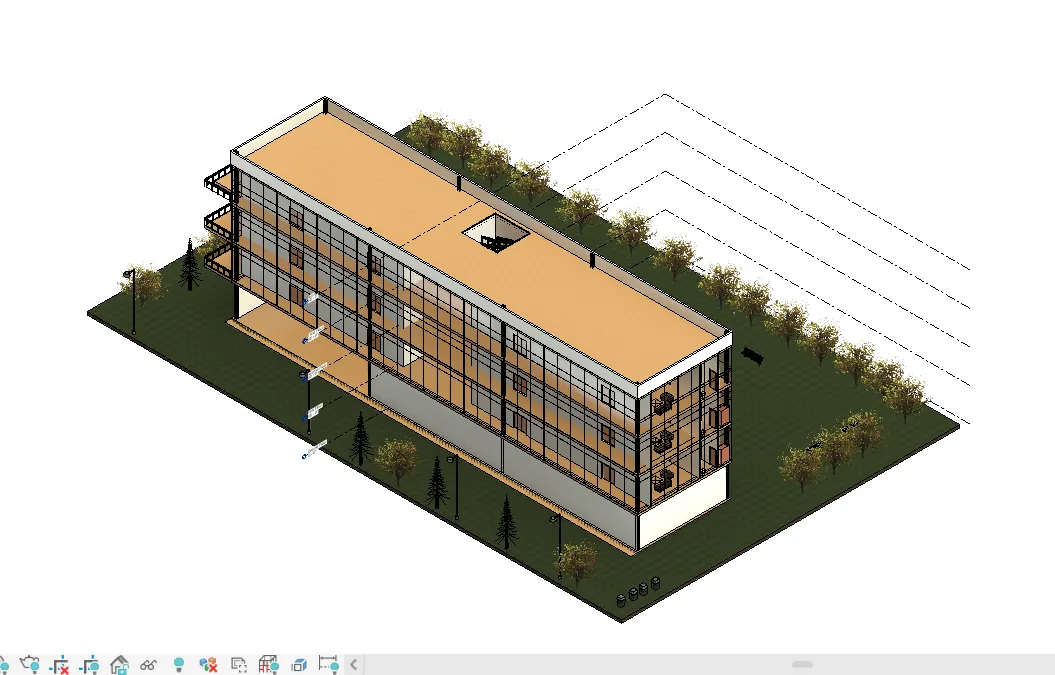
- Front view of the building
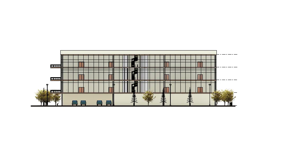
- Back view of the building.
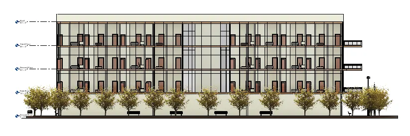
Result:
5) Provide a set of drawings in an architectural and structural model to list the following details with categories and appropriate sheet templates included
a. Floor Plans with Annotations
b. Elevations
c. Sections
Aim:
To create the Floor plans, Elevation and Section of the Architectural and Structural Model.
Introduction:
Create a Floor plans, Elevation and Section of the Architectural and Structural model using the View Tool bar with the Details.
Procedure:
- Go to the View Toolbar.
- Select the Floor plans.
- Select the Ground Floor, First floor, Second floor,Third floor and Roof in the Architectural Model.
- Select the Floor plan for the Structural Model.
- Ground Floor plan for the Architectrual Model.
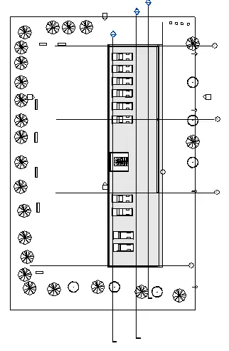
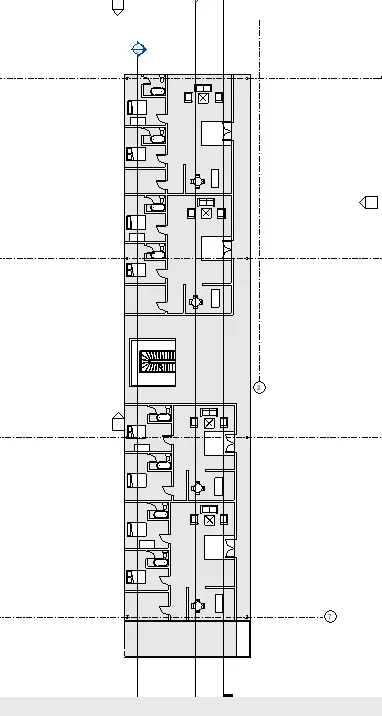
- First Floor plan for the Architectural Model.
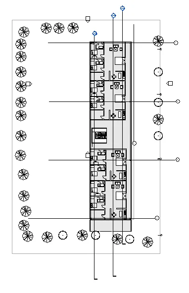
- Second Floor plan for the Architectural Model.
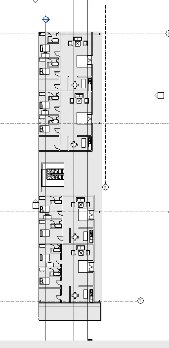
- Third Floor plan for the Architectural Model.
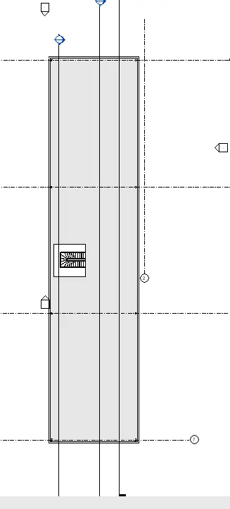
- Roof plan for the Architectural Model.
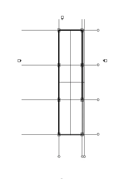
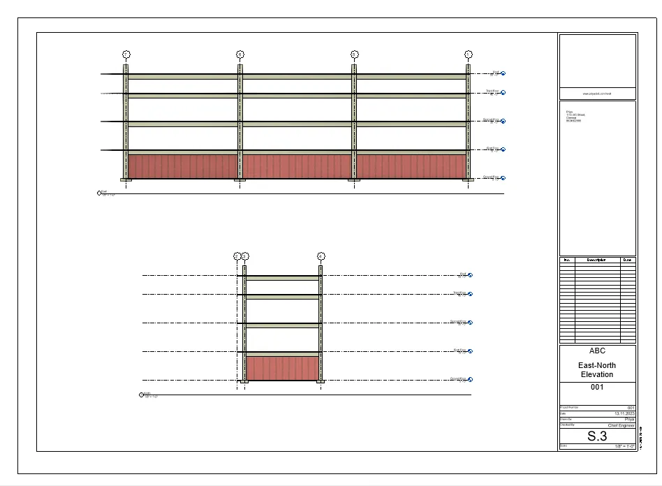
- Floor Plan for the Structural Model.
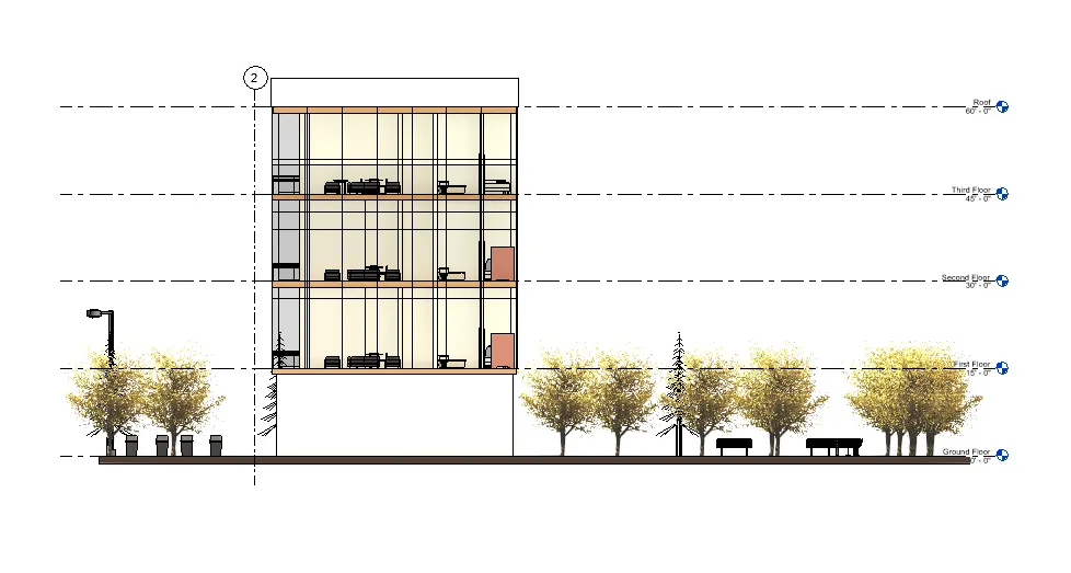
- Go to the View tool bar or the property browser the select the East, North, South and West Elevation.
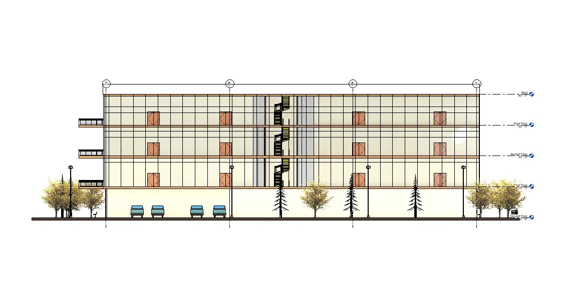
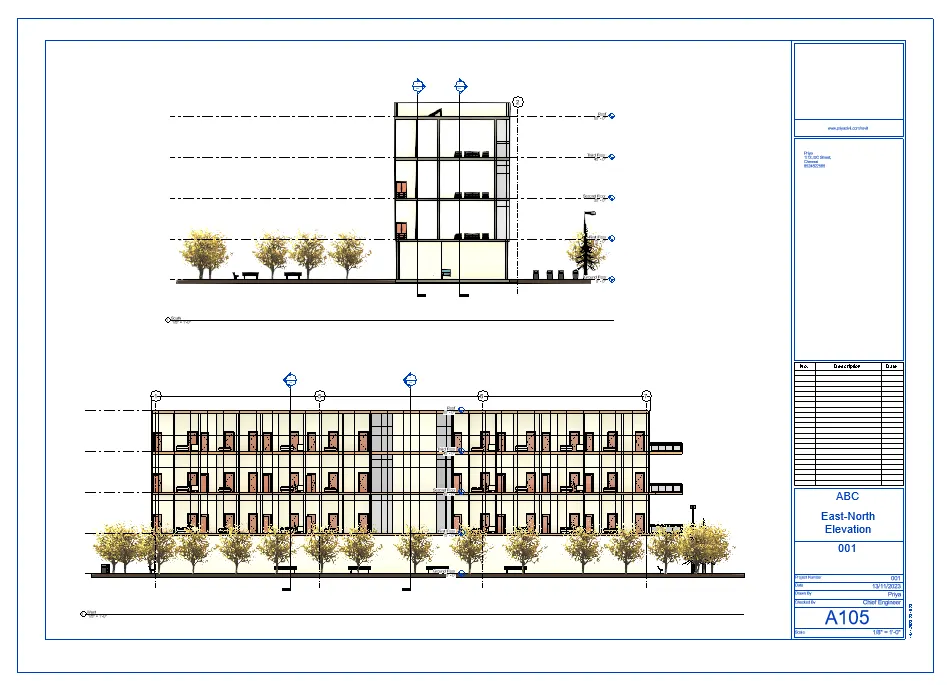
- East Elevation of the Architectural Model.
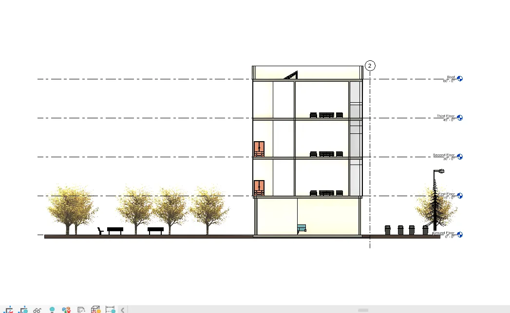
- North Elevation of the Architectural Model.
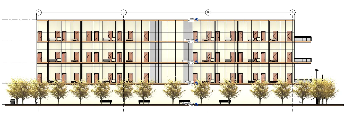
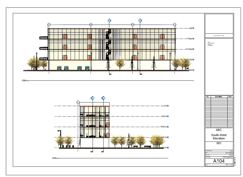
- South Elevation of the Architectural Model.
- West Elevation of the Architectural Model.
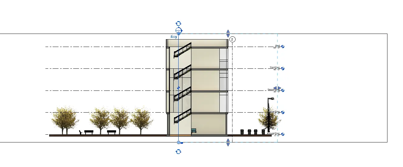
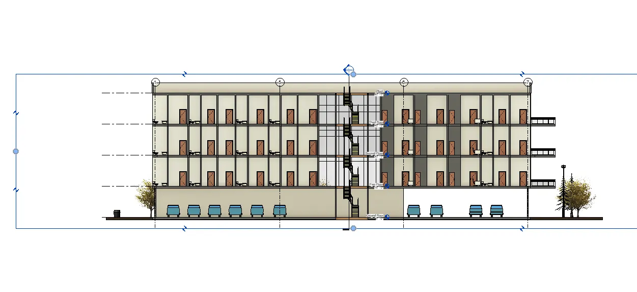
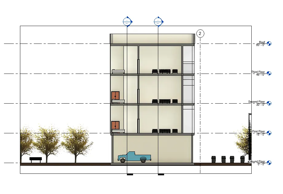
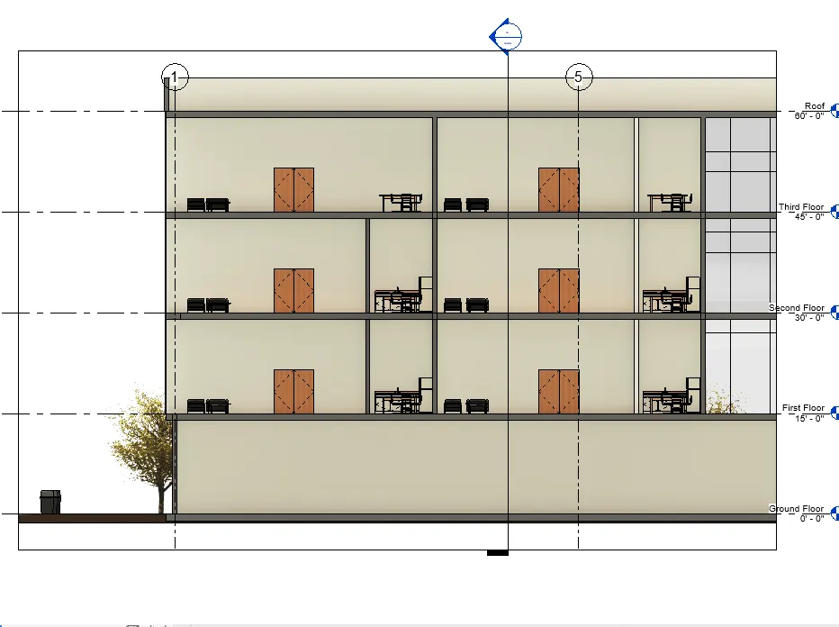
- Go to the View toolbar.
- Select the section.
- Then cut the Section through the floors.
6) Using the Rendering settings, Render images of the 3D model produced and include the rendered images to the drawing sheets
a. Rendering from interior rooms
b. Rendering from out showing topographic features
c. Rendering through structural framing
Aim:
To Render the Architectural and Structural Model.
Introduction:
Render the Architectural and Structural Model and also the Images of the Individual 3D Image of Interior rooms.
Procedure:
- Go to the Image of the 3D Bed room.
- Then Go to the View toolbar.
- Select the Render.
- Change the properties of the render.
- Then click render.
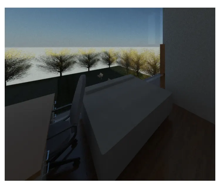
- Render image of the Bed room.
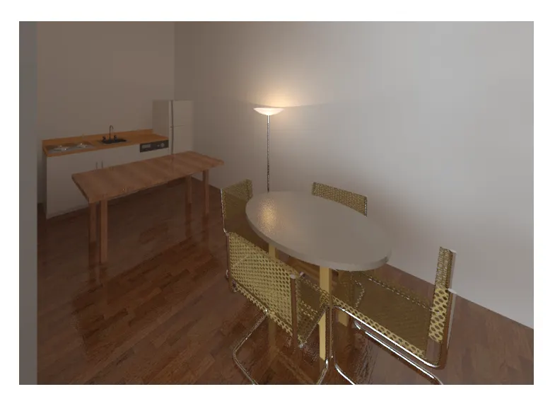
- Go to the Image of the 3D Kitchen.
- Then Go to the View toolbar.
- Select the Render.
- Change the properties of the render.
- Then click render.
- Render image of the Kitchen and Dining.
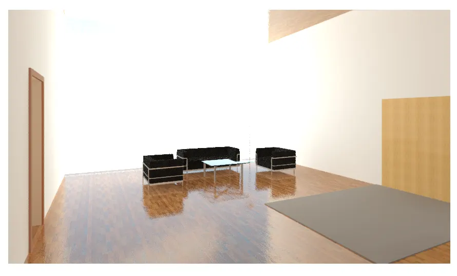
- Go to the Image of the 3D Living room.
- Then Go to the View toolbar.
- Select the Render.
- Change the properties of the render.
- Then click render.
- Render image of the Living room.
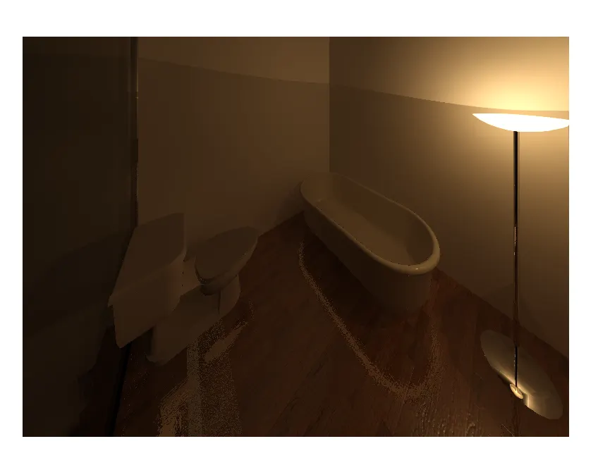
- Go to the Image of the 3D Rest room.
- Then Go to the View toolbar.
- Select the Render.
- Change the properties of the render.
- Then click render.
- Render image of the Rest room.
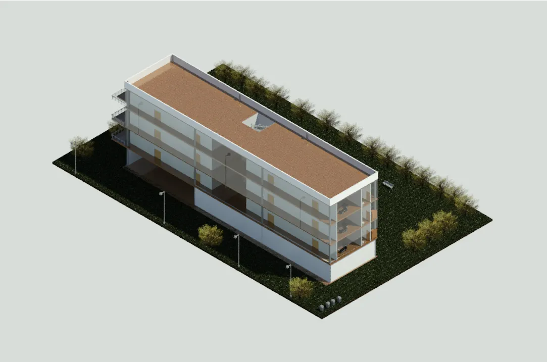
- Go to the Image of the 3D Architectural Model.
- Then Go to the View toolbar.
- Select the Render.
- Change the properties of the render.
- Then click render.
- Render image of the Architectural Model.
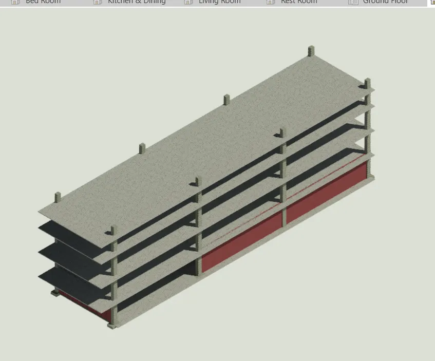
- Go to the Image of the 3D Structural Model.
- Then Go to the View toolbar.
- Select the Render.
- Change the properties of the render.
- Then click render.
- Render image of the Structural Model.
7) Print the set of drawing sheets created and submit the drawings from the architecture and structure model
Aim:
To Create the Sheets and submit the drawing from the architectural and structural model.
Introduction:
Create the sheets and submit the Architectural Interior rooms and Structural model to the sheets and edit the information of the sheets.
Procedure:
- Go to the View toolbar.
- Select the sheets.
- Edit the Information of the Sheets.
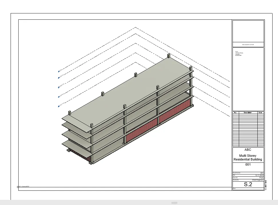
- Then Select the 3D Structural model and drag it to the sheet.
- Go to the View toolbar.
- Select the sheets.
- Edit the Information of the Sheets.
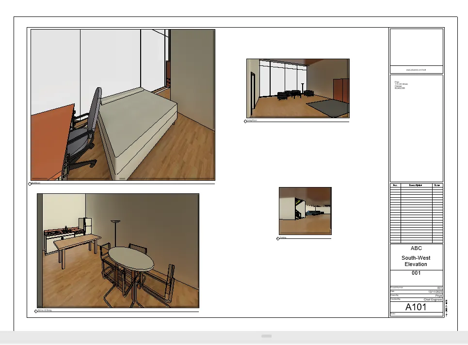
- Then Select the 3D Architectural Interior rooms like Bed room, Living Room, Kitchen and Dining, Ground Floor and drag it to the sheet.
- Go to the View toolbar.
- Select the sheets.
- Edit the Information of the Sheets.
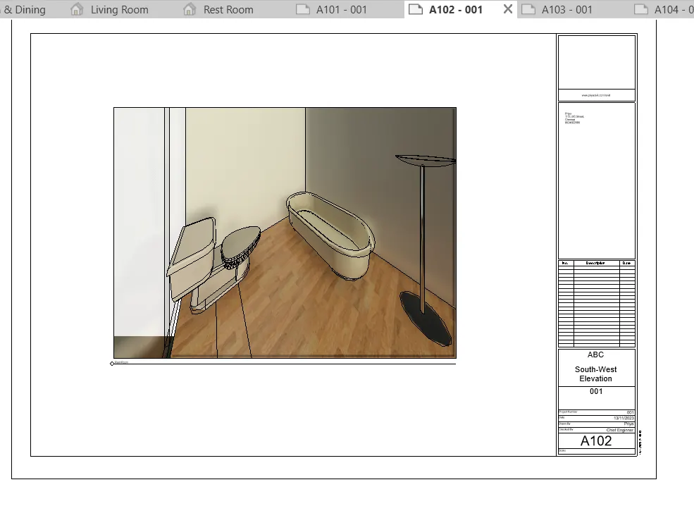
- Then Select the 3D Rest Room and drag it to the sheet.
- Go to the View toolbar.
- Select the sheets.
- Edit the Information of the Sheets.
- Then Select the 3D Architectural model and drag it to the sheet.
- Go to the View toolbar.
- Select the sheets.
- Edit the Information of the Sheets.
- Then Select the South and West Elevation and drag it to the sheet.
- Go to the View toolbar.
- Select the sheets.
- Edit the Information of the Sheets.
- Then Select the East and North Elevation and drag it to the sheet.
- Go to the View toolbar.
- Select the sheets.
- Edit the Information of the Sheets.
- Then Select the East and North Elevation of the structural model and drag it to the sheet.
- Go to the View toolbar.
- Select the sheets.
- Edit the Information of the Sheets.
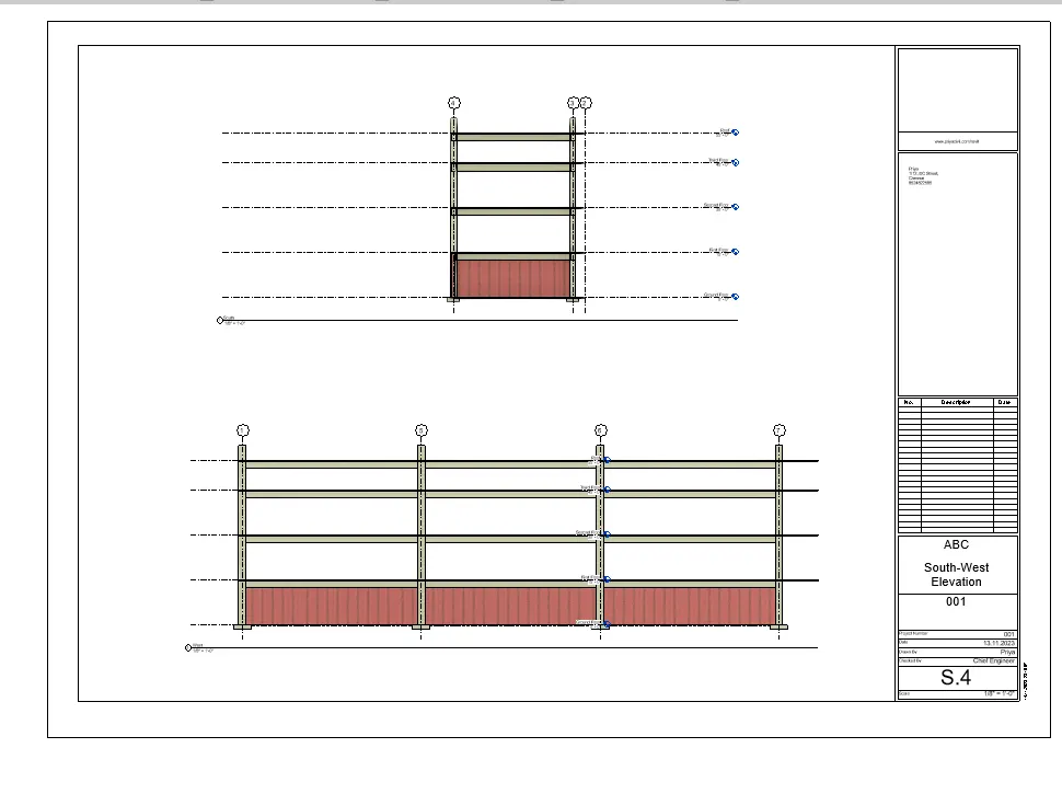
- Then Select the South and West Elevation of the structural model and drag it to the sheet.