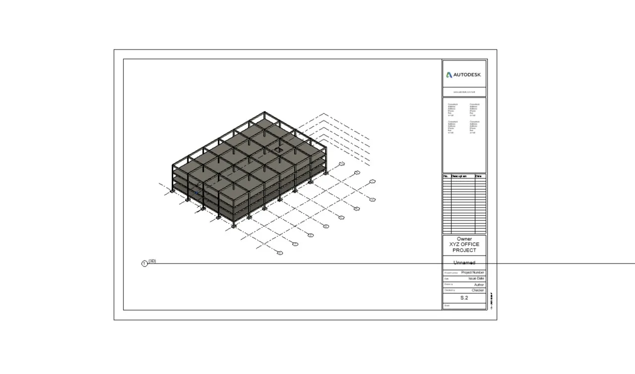
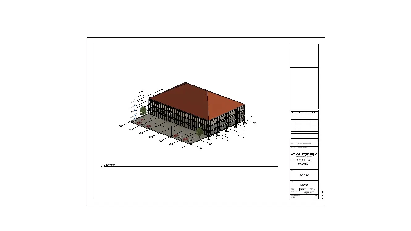
Creating Architectural and Structural model with 3D rendering using REVIT
1. From the options i will select OFFICE BUILDING
2. AIM :
Assume the reasonable assumptions for geographical location details for your project modelling.
Based on the assumptions and the type of structure selected identify the modelling requirements from NBC.
PROCEDURE :
I will assume the that the project is in plain area and it is a commercial area.
Road width in front of the building structure is 70feet.
MODELLING REQUIREMENTS AS PER NBC ARE :
The minimum height of the basement should be 2.5m and maximum height should be 4.5m
As per NBC exit should be provided in each floor for easy escape of employees from building if in case of earthquakes or fire hazards.
3. AIM :
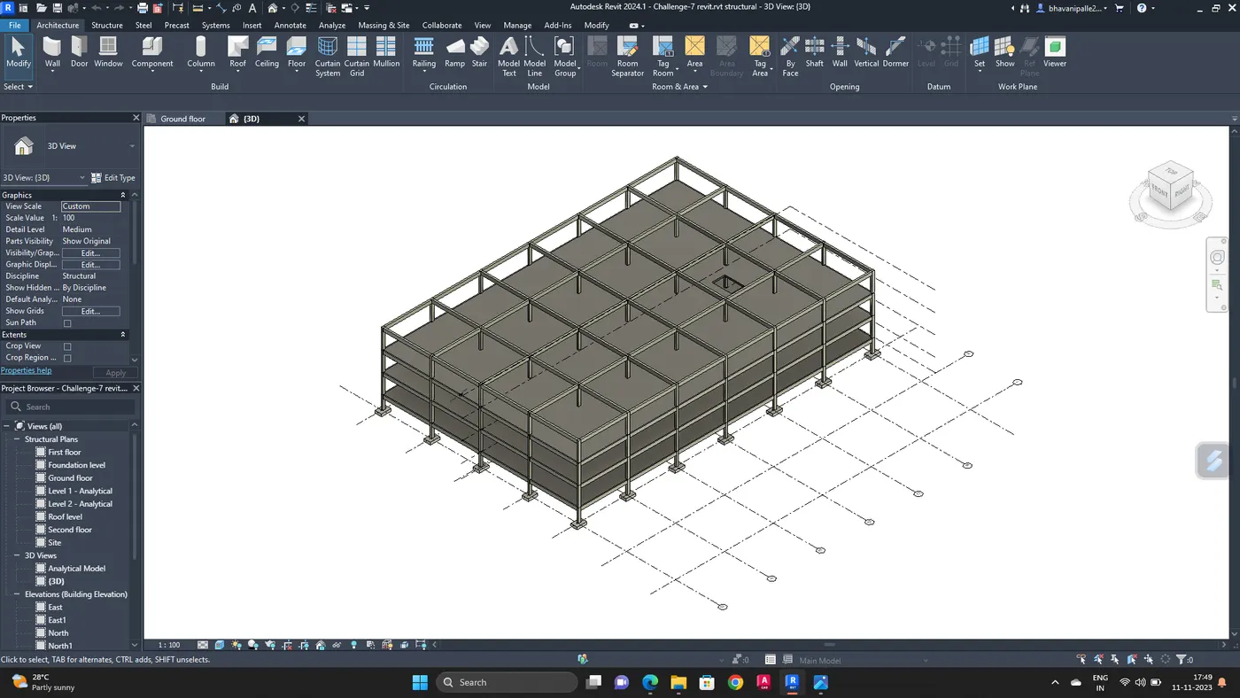
Using the structural model, include the following components based on the type of structure selected
1. Foundation
2. Columns
3. Beams connected to columns
4. Roof framing
5. Floor
6. Floor openings for elevators
PROCEDURE :
Open revit software
Go to new and select structural template
Save the file by giving appropriate name of the file
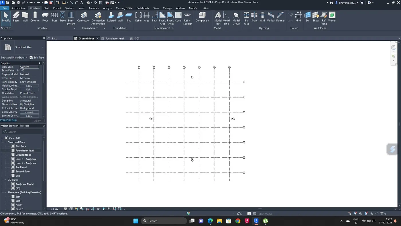
Go to structural tab, select the grid line
Draw transverse and longitudinal grid lines with 30' distance
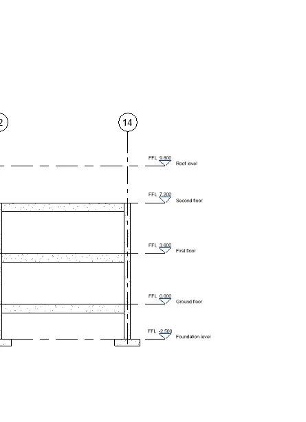
Go to elevation view and create the levels till roof level and change their names respectively
Go to structure tab select isolated footing and add footing at every grid joints in foundation level that we created.
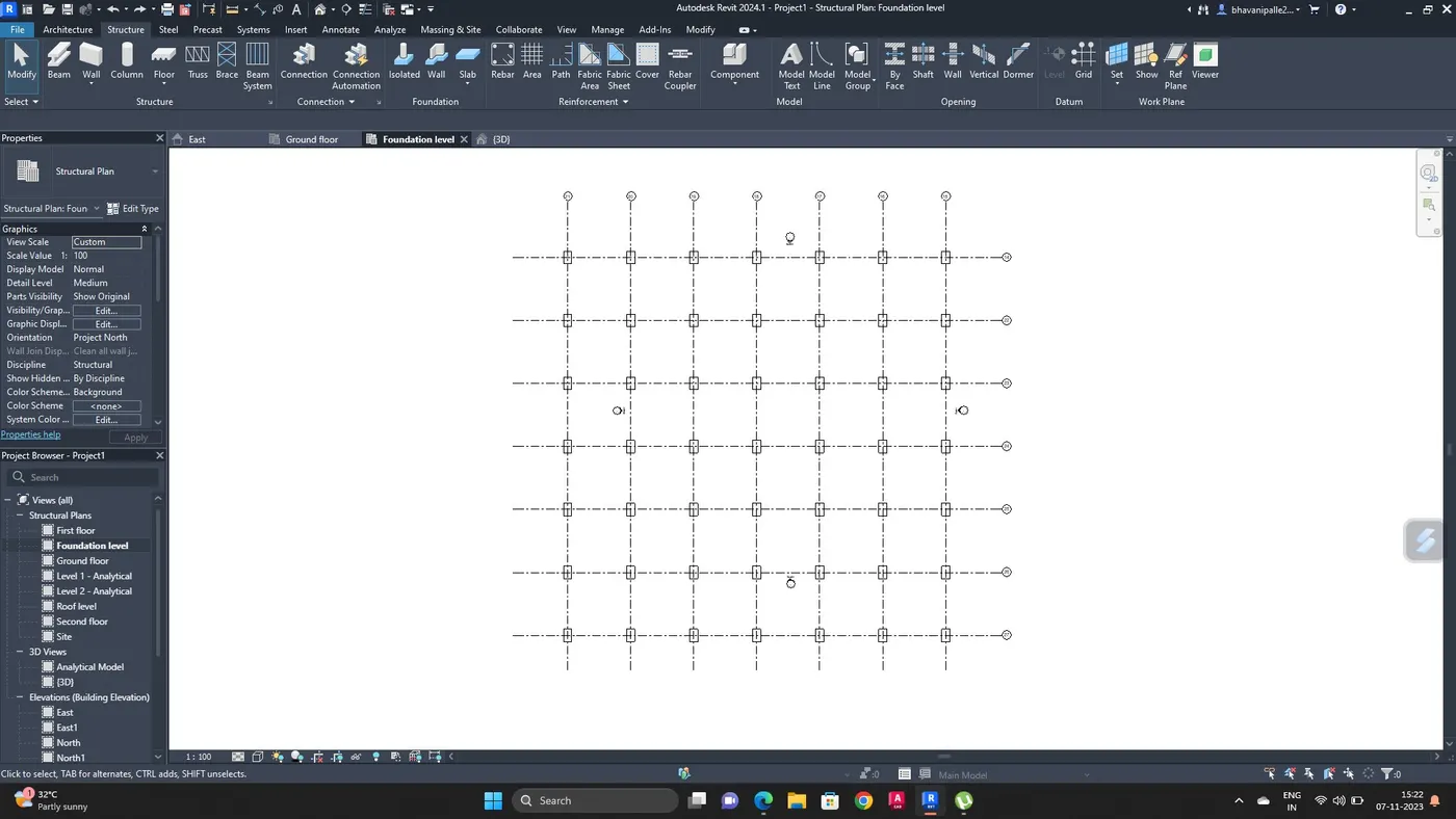
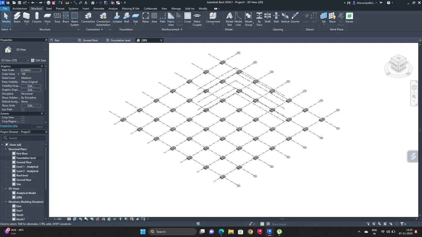
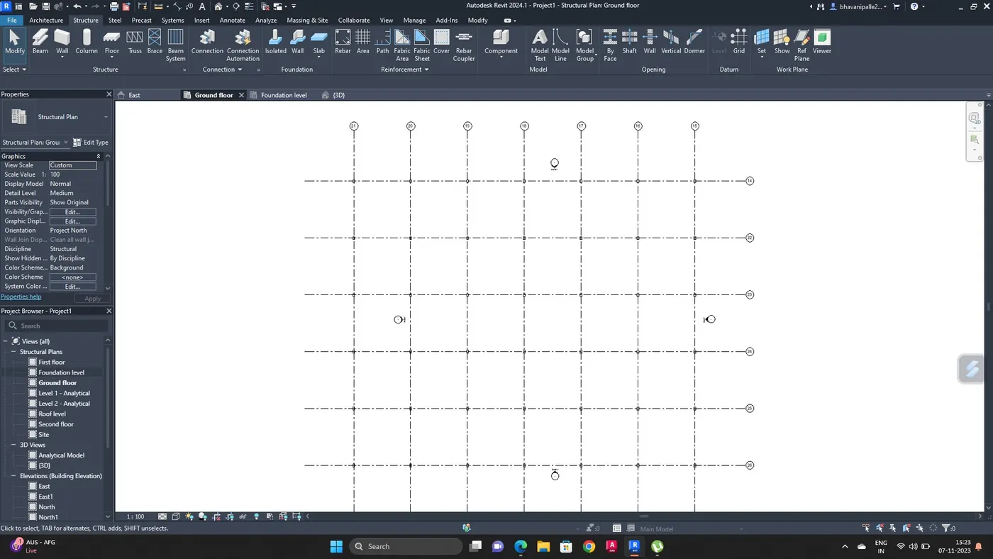
Go to structural tab select column and add columns at every grid joints in ground level
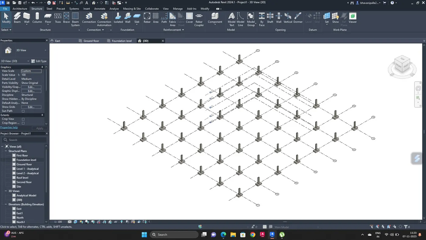
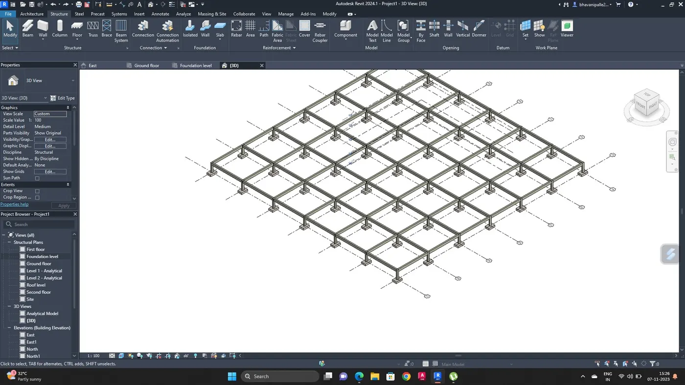
Go to 3D view to see the realistic view
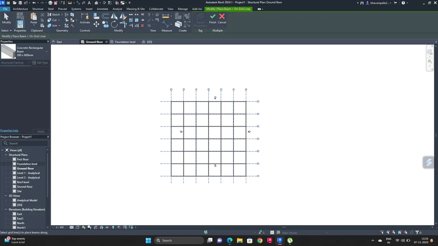
Select beam and add beam at between each columns in ground level
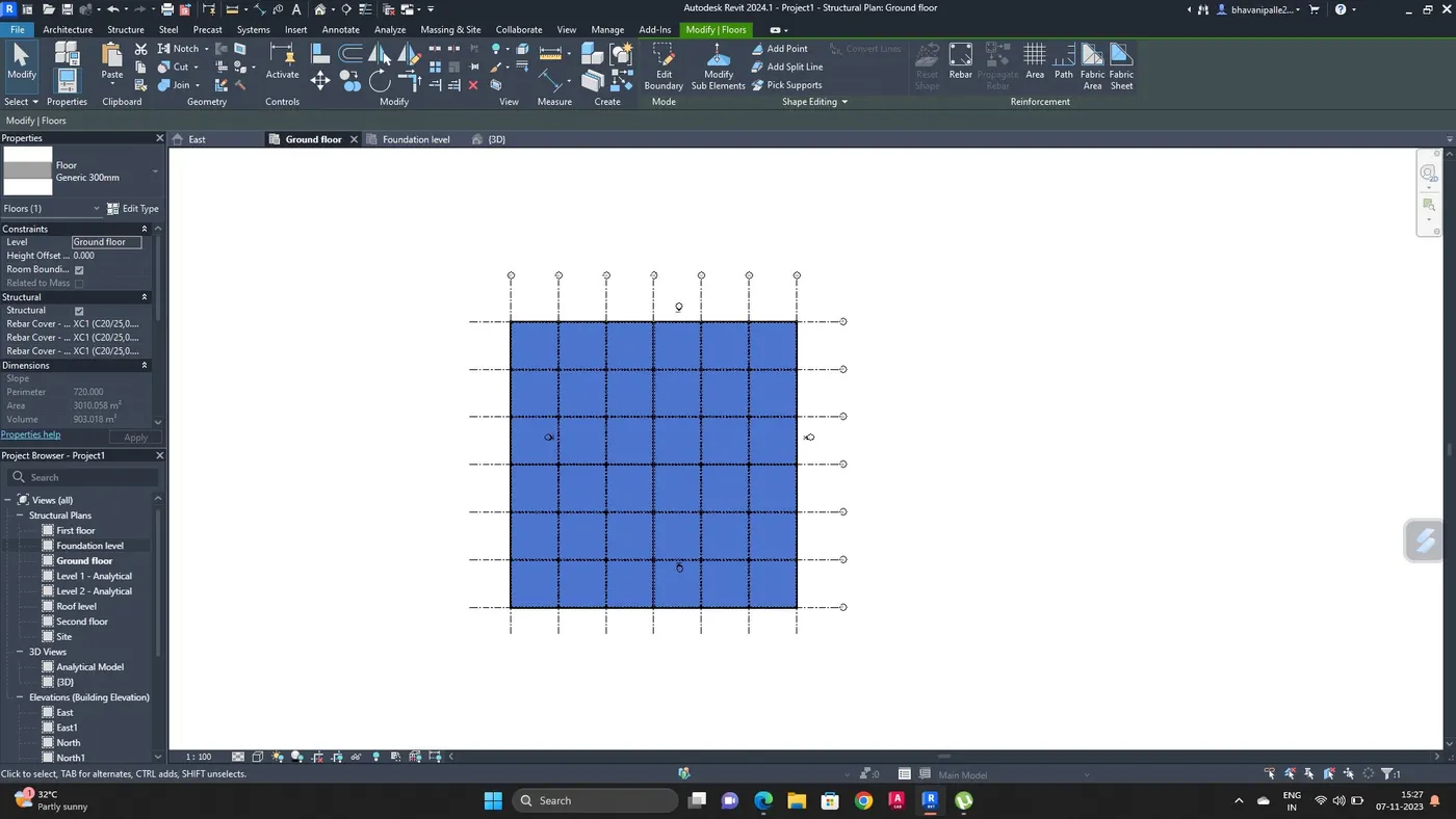
Go to structure tab select floor and add floor to the project
Copy the elements which are in ground floor like, columns, beams and floor and paste it to the selected levels i.e upto roof level.
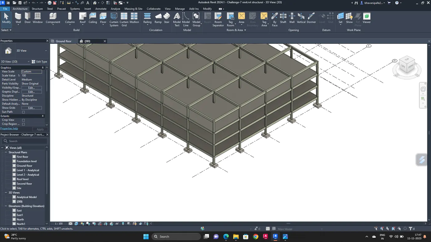
By using shaft create openings
4. AIM :
Using architectural model inculde the following components based on the type of structure selected
a. wall layout with appropriate material and finishing
b. exterior facade with fancy finish
c. interior partition walls to size rooms
d. components to add details to a room (Desk, chair, lighting, plumbing fixtures)
e. add components such as stairs elevators
f. have at least one side building with curtain walls and glass panels
g. inculde interior and exterior lighting fixtures
h. place proper topographic components from outside to add details to the model.
PROCEDURE :
Open new revit file with architectural template and link the structural file to the architectural file
Go to collabrate tab, select copy and monitor
Copy the elements
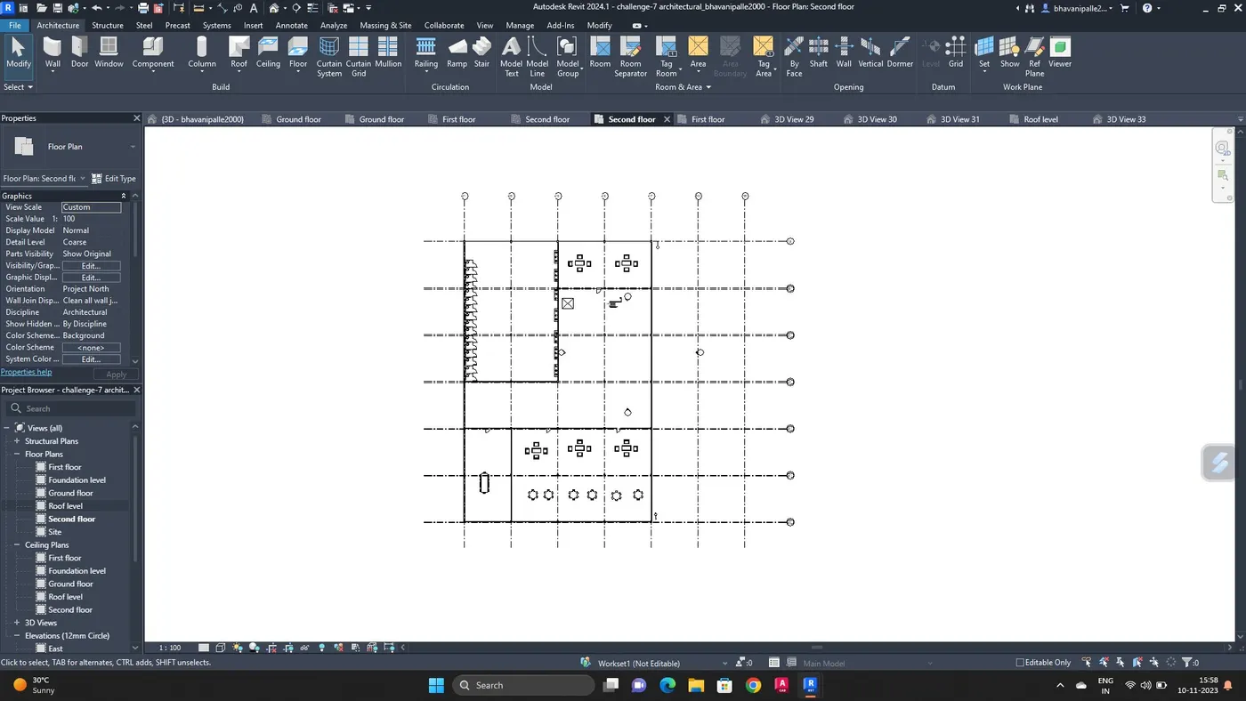
Draw external walls and interanl walls according to grid lines
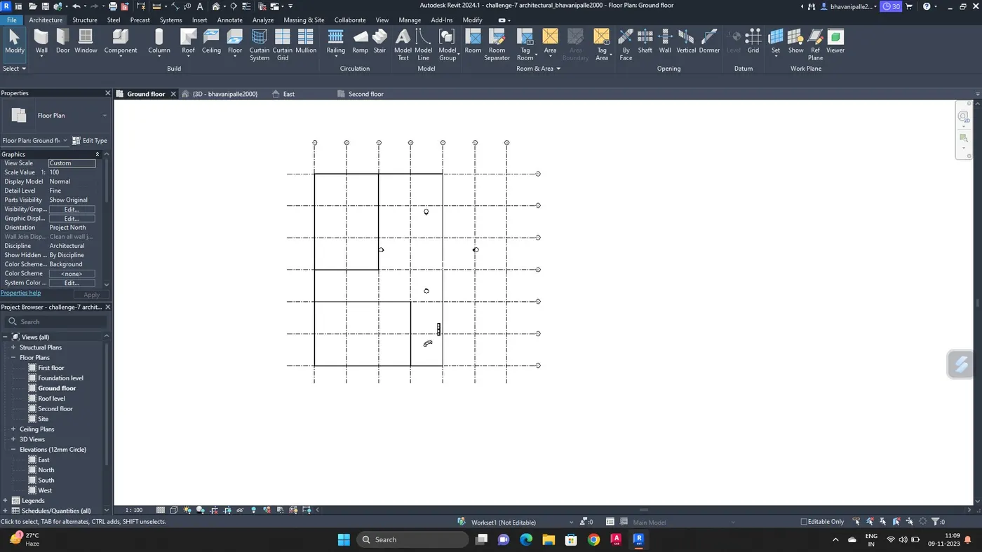
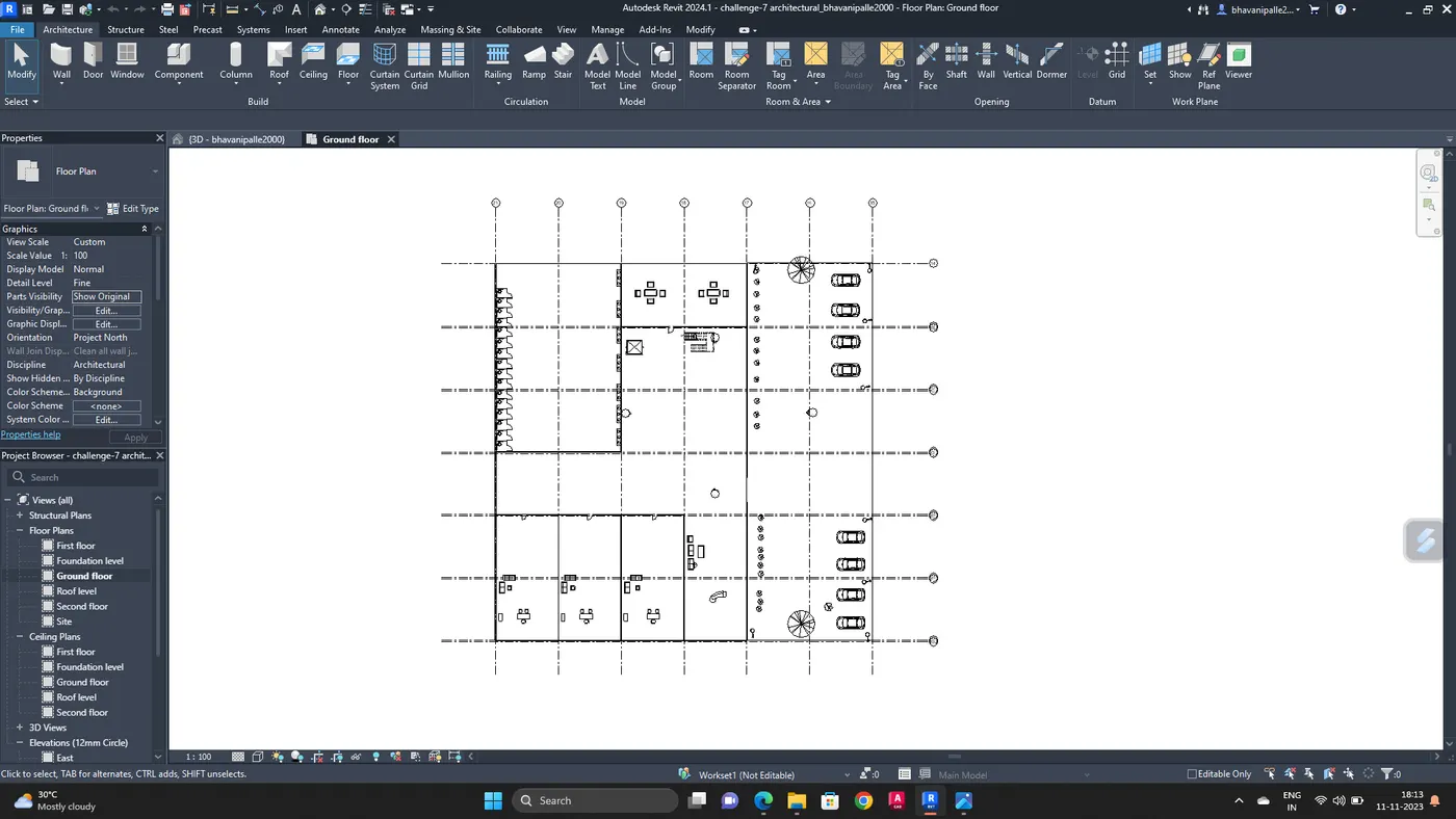
Add components like doors and furniture components according to the requirements
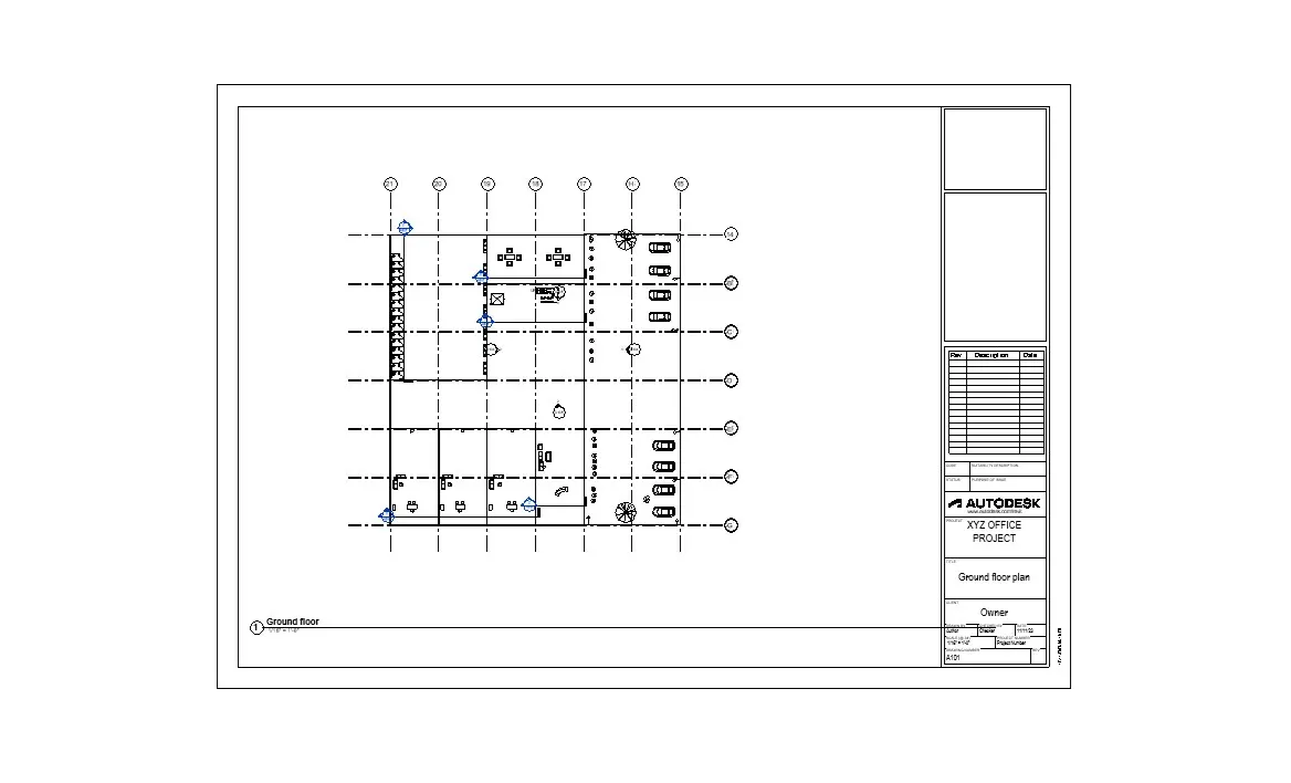
Ground floor
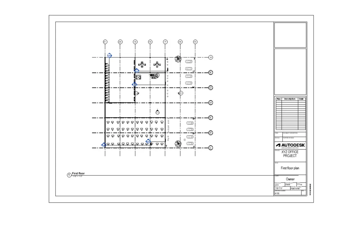
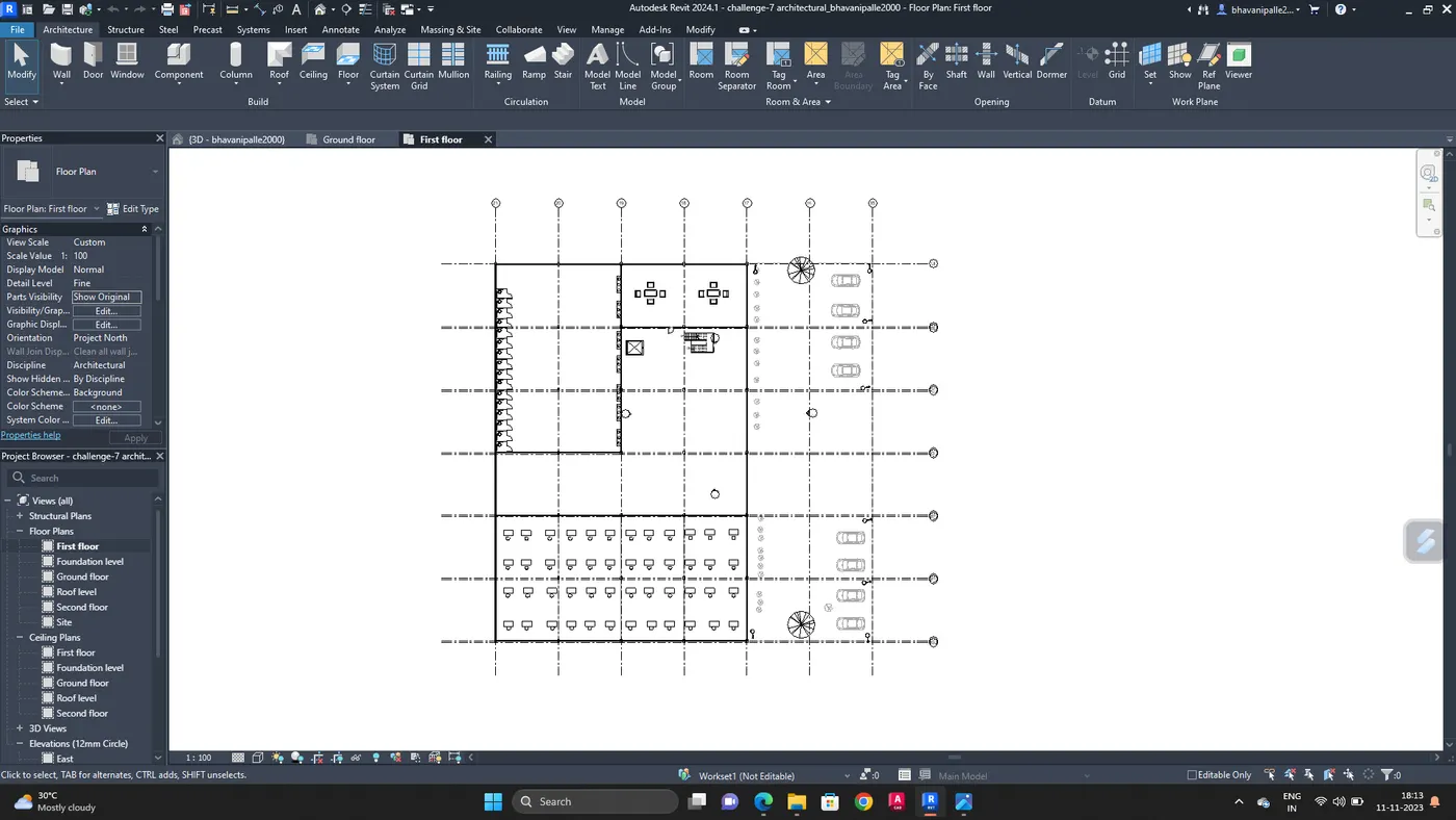
First fllor
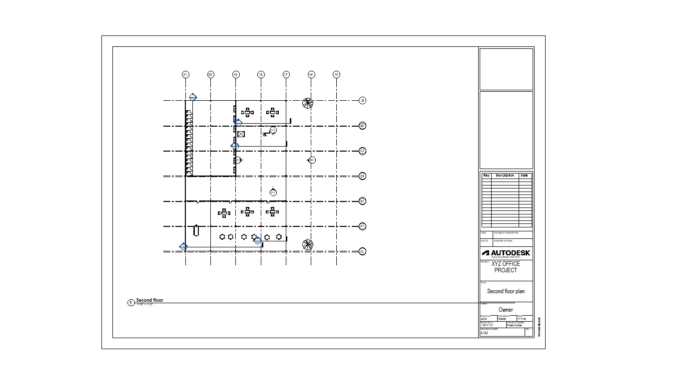
Second floor
3D view
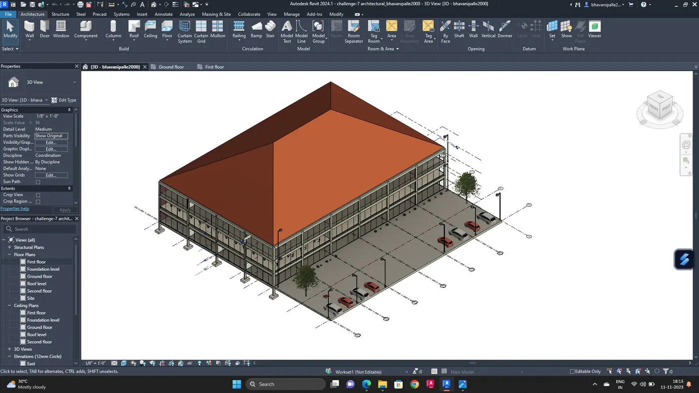
Add ceiling lights and exterior lights
Go to ceilings which is present in the project browser
Go to architecture tab, select ceiling
Add ceiling
Select components, load family, lighting, add lights to the ceiling
Add topographical components to the model wherever required
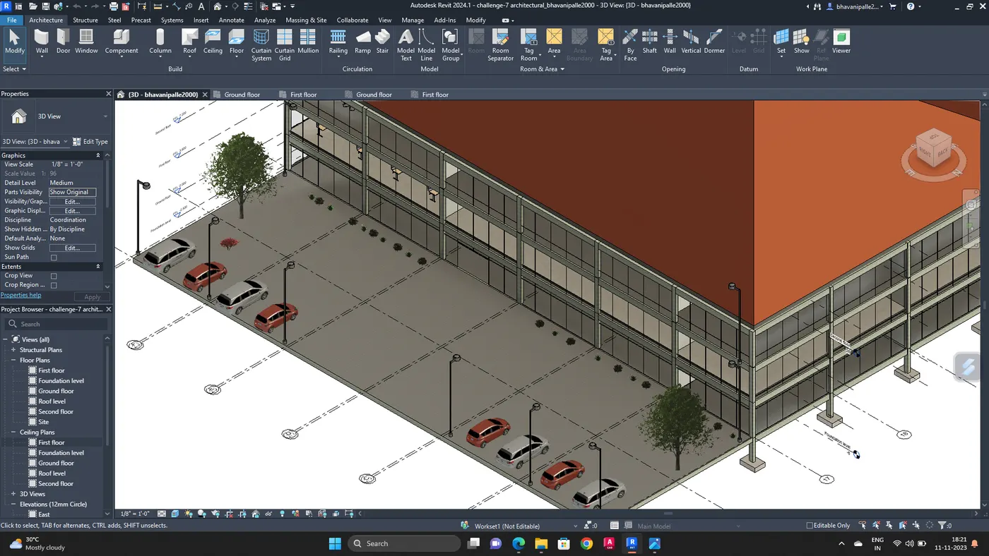
RESULT :
Given challenge is complted by using necessary tools in revit software
5. AIM :
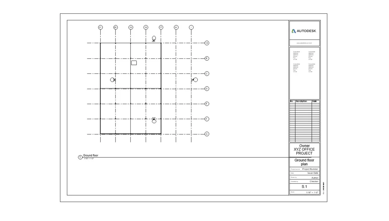
To provide a set of drawings in an architectural and structural model to list the following details with categories and appropriate sheet templates included
a. Floor plans with annotations
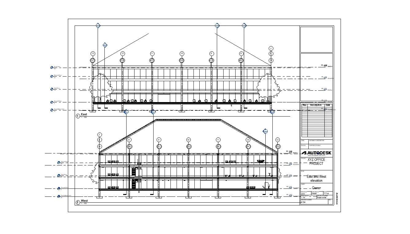
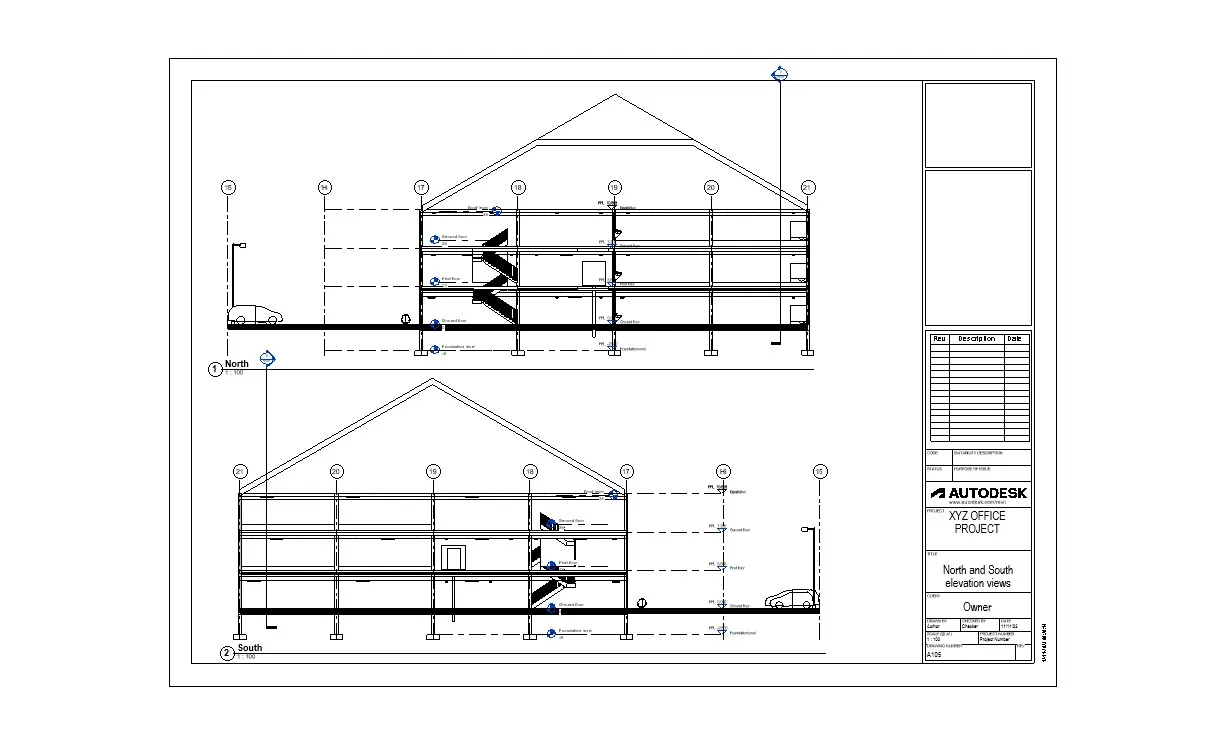
b. Elevations drawing
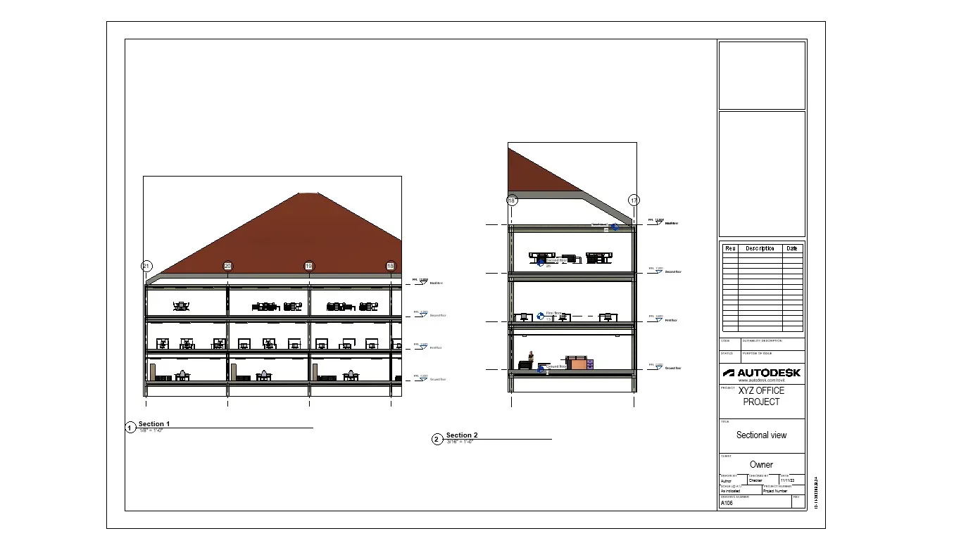
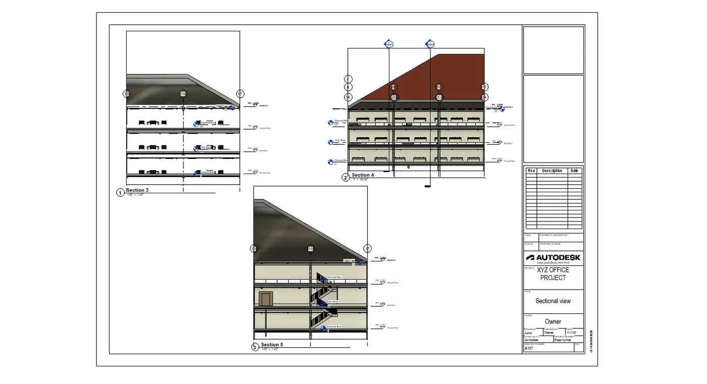
c. Sections
PROCEDURE :
Go to view tab and select sheet
Template sheet is displayed
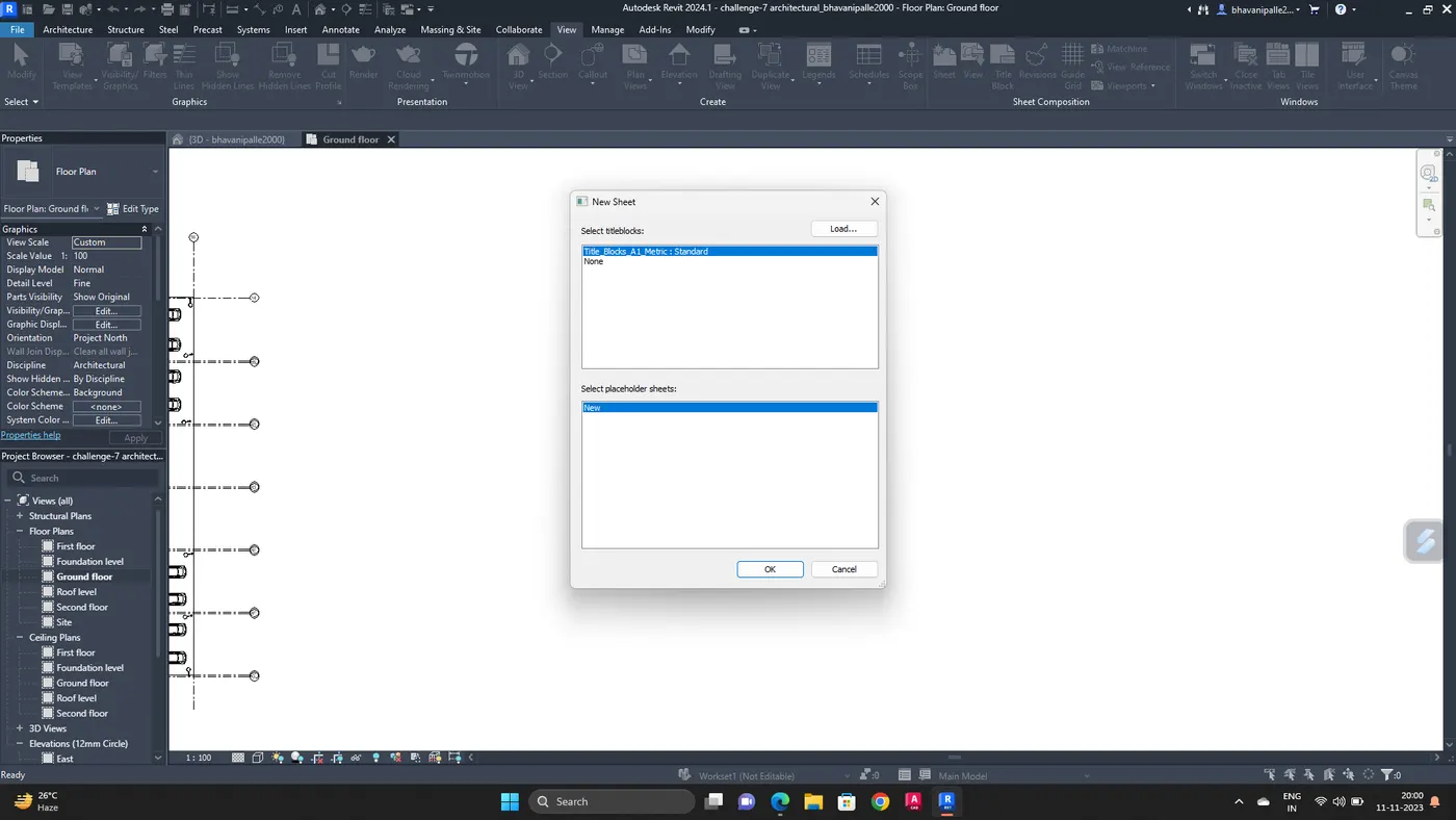
Edit the sheet according to the requirements and add the views
Adjust the scale and insert the ground floor plan into the sheet
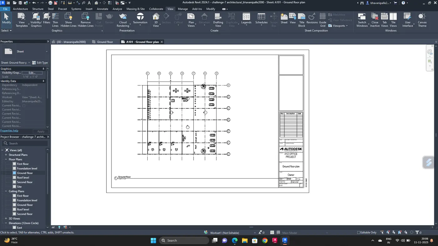
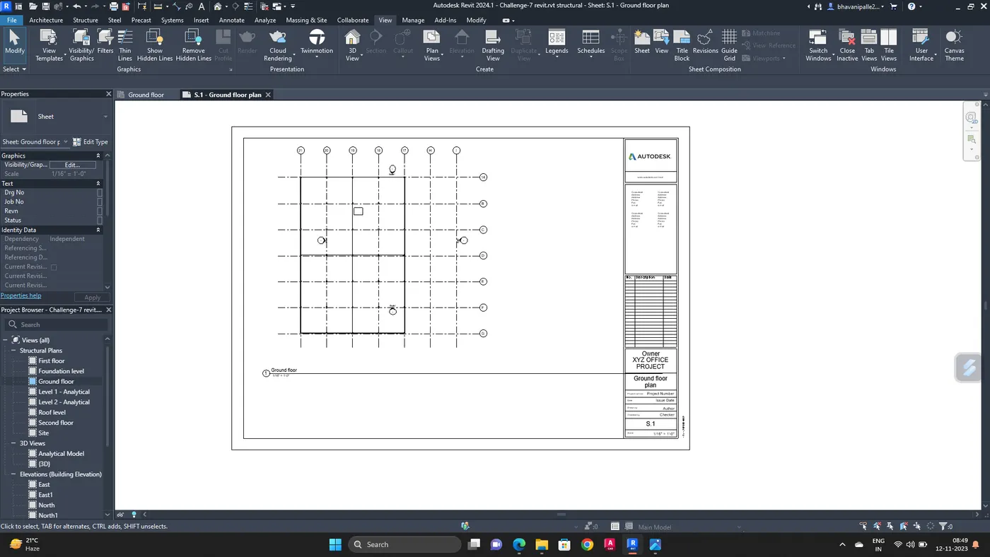
Take another sheet, rename it and,
Add first floor plan
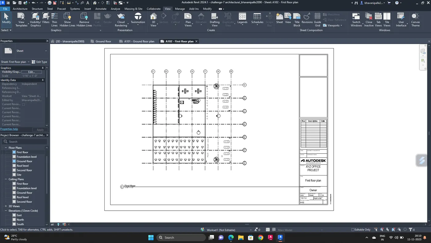
Second floor plan
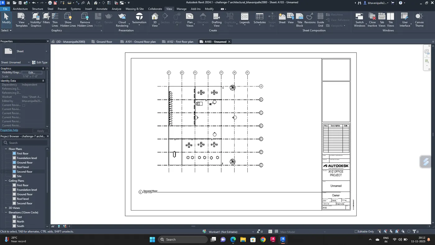
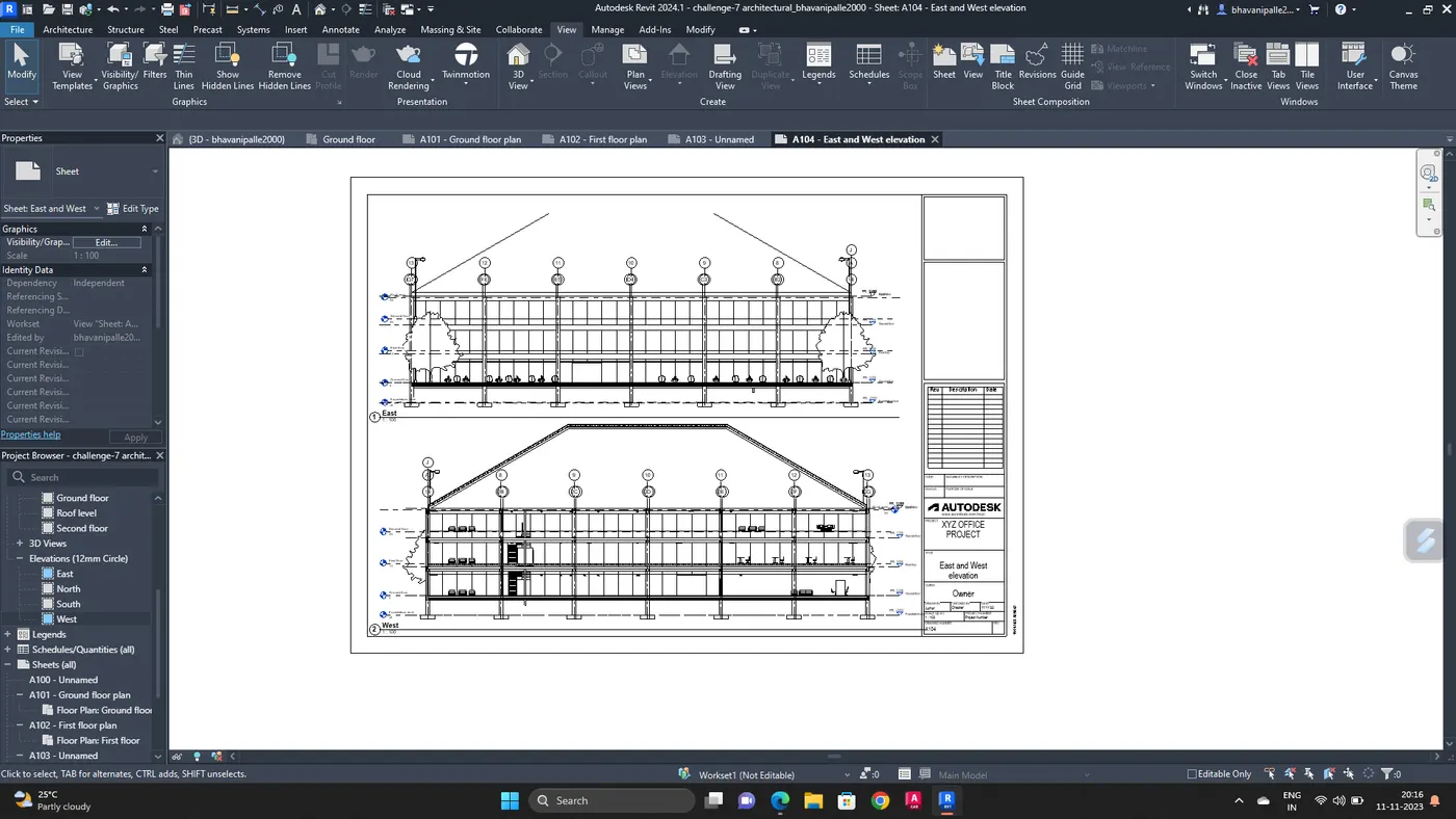
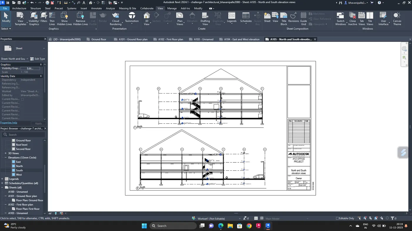
Add Elevation views into the sheets
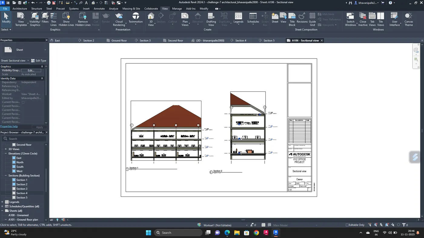
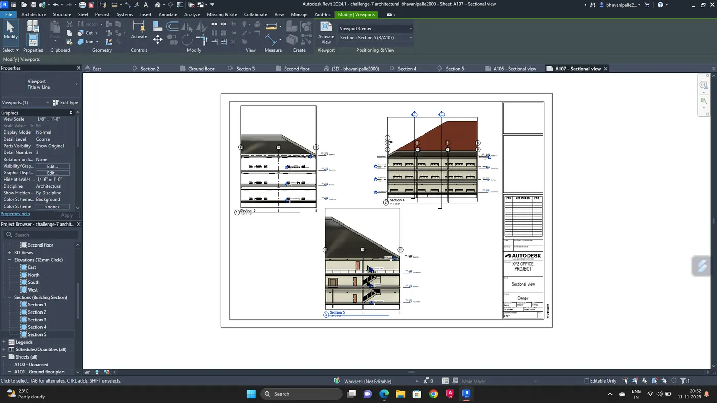
Add sectional views into the sheets
Add 3D view
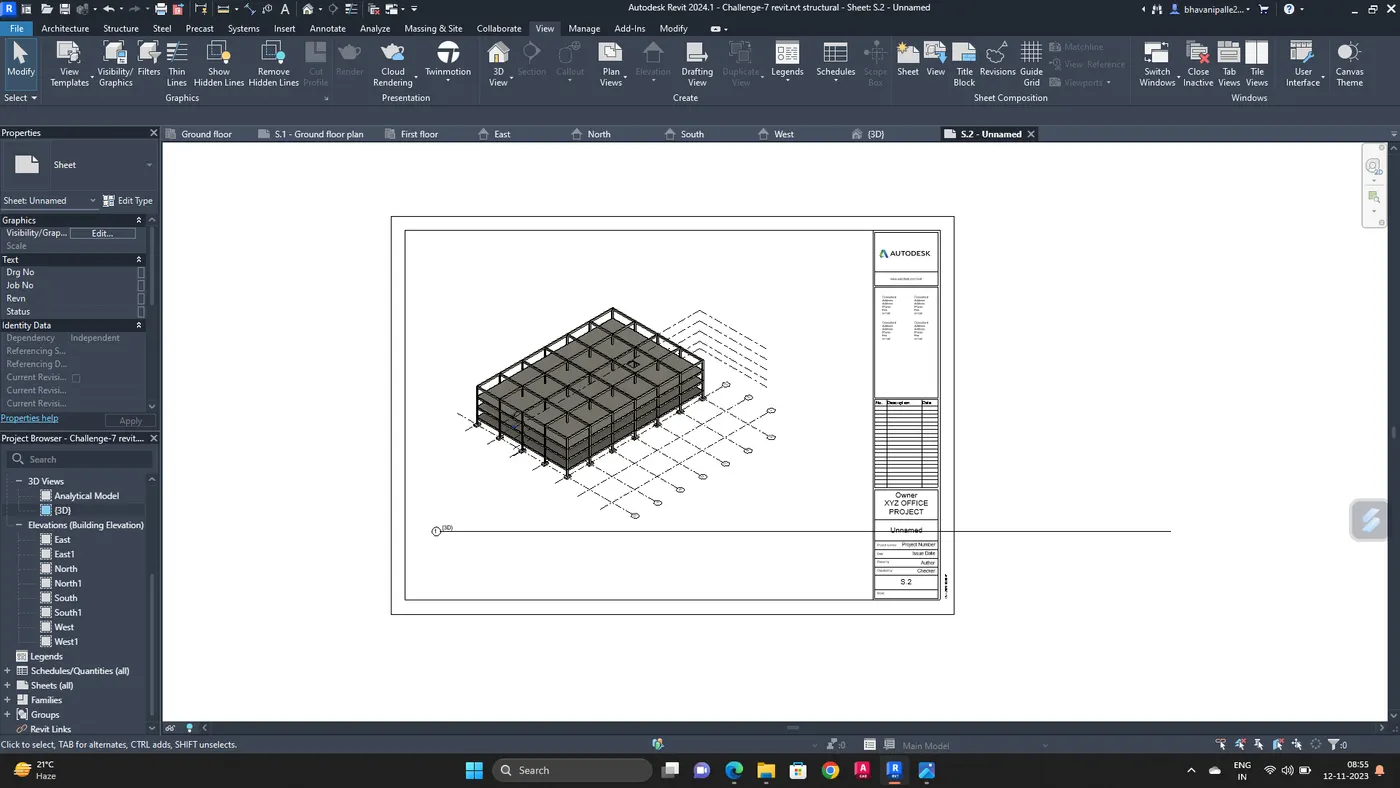
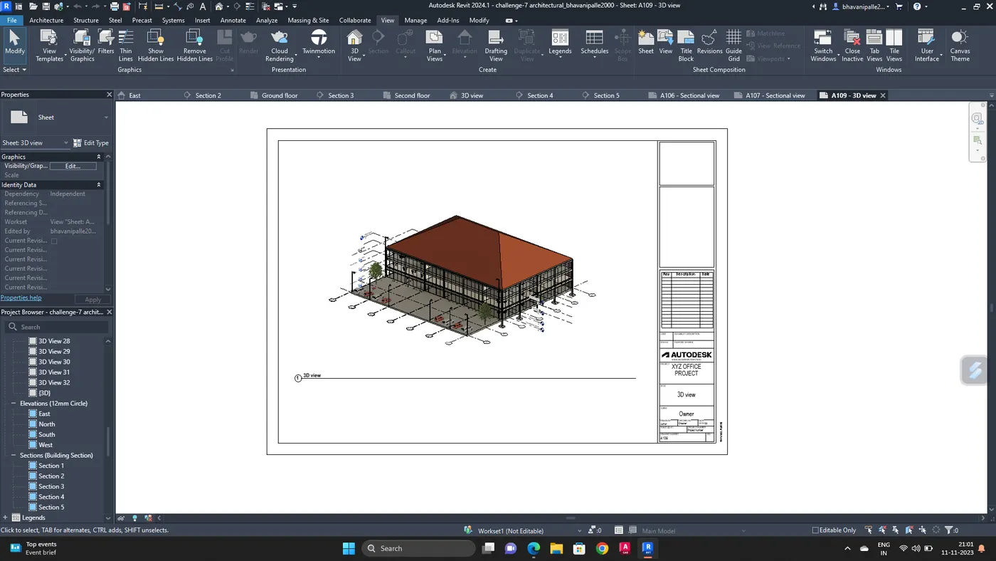
RESULT :
Sheet templates are created and the drawings are added to the sheet.
6. AIM :
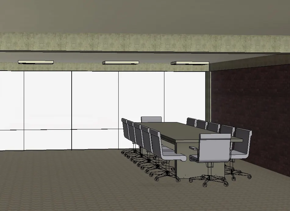
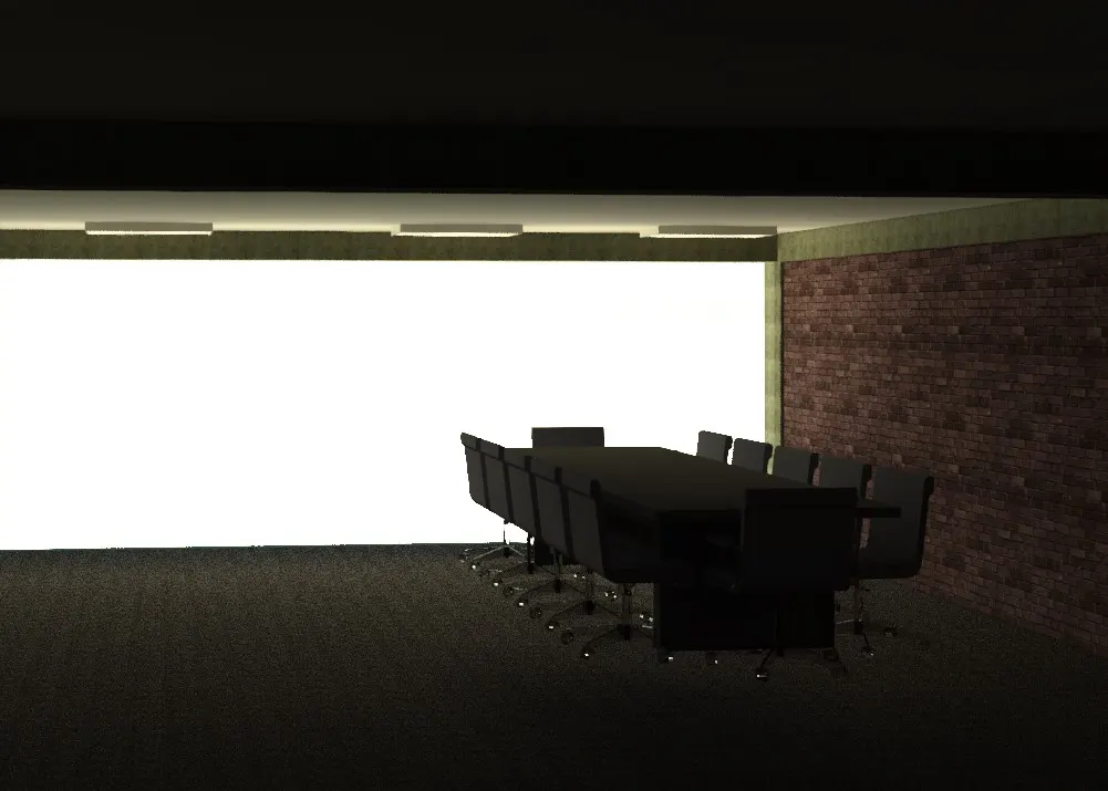
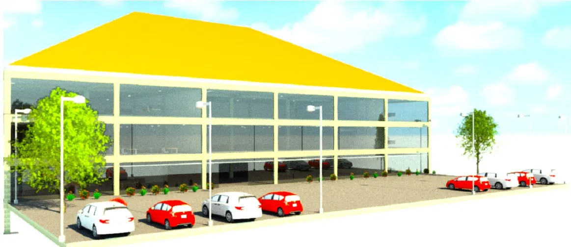
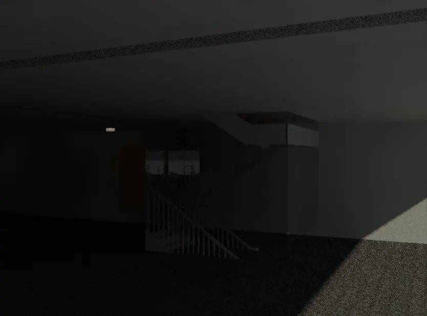
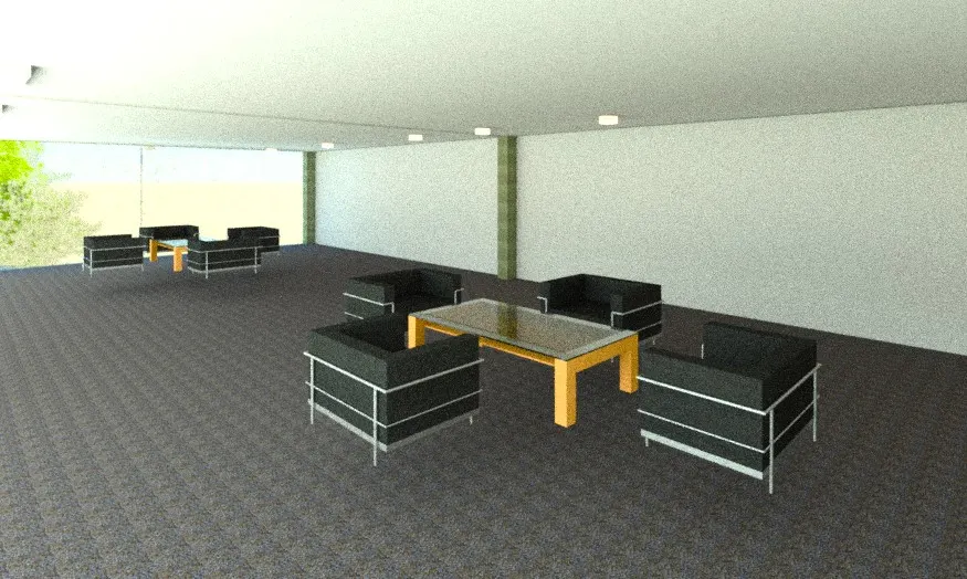
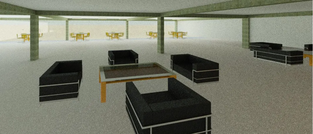
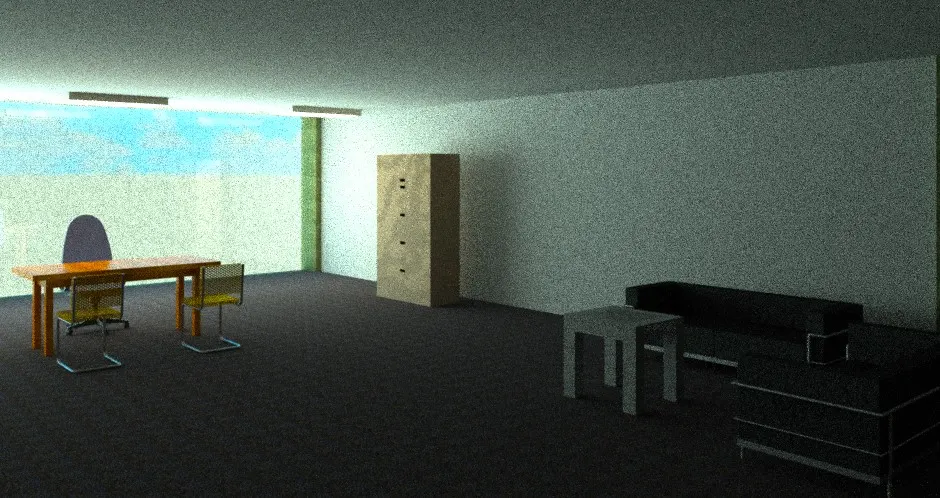
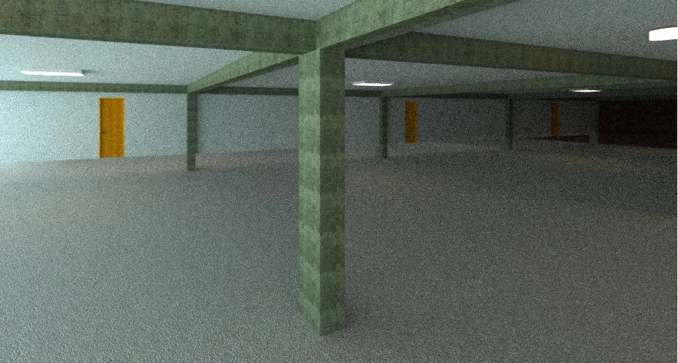
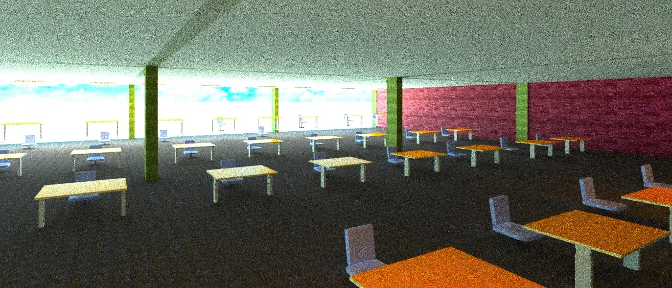
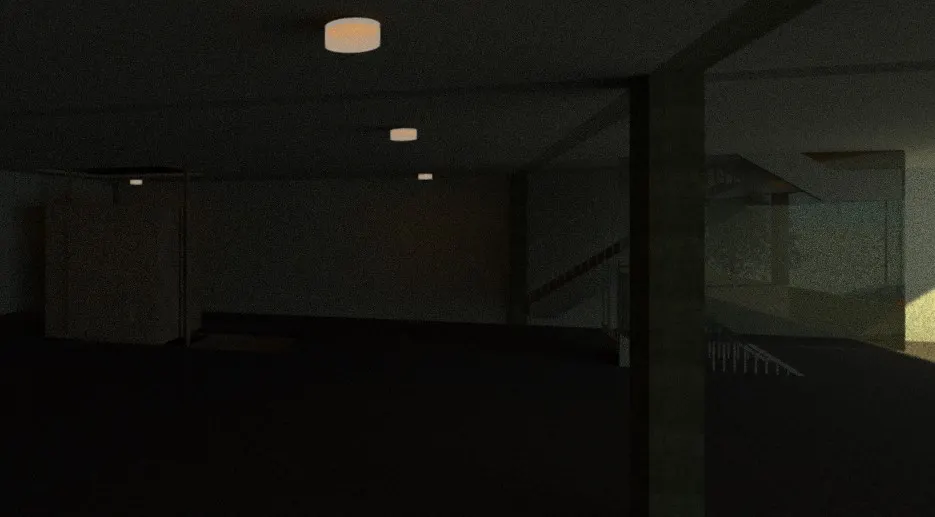
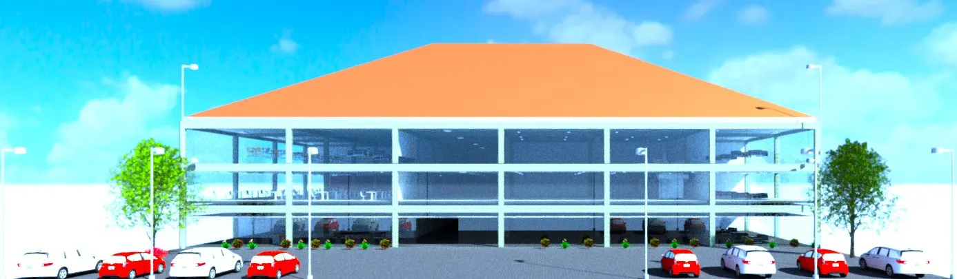
Using rendering settings, render images of the 3D model produced and include the rendered images to the drawing sheets
a. Rendering from interior rooms
b. Rendering from out showing topographic features
c. Rendering through structural framing
PROCEDURE :
Go to view tab, select camera and set camera views
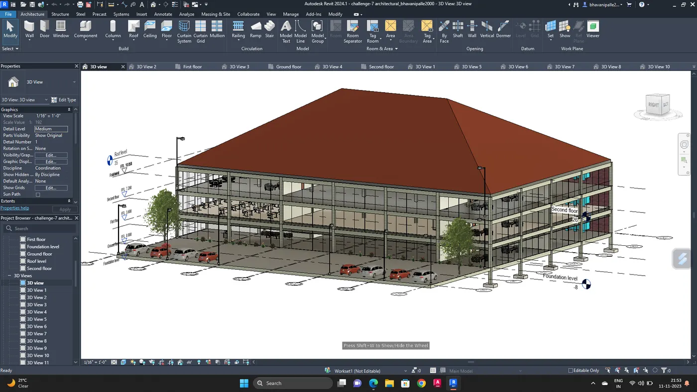
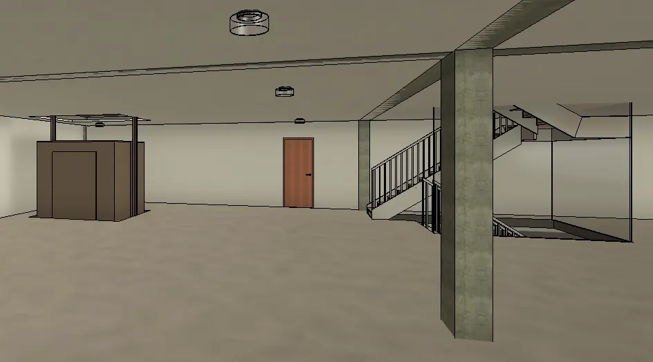
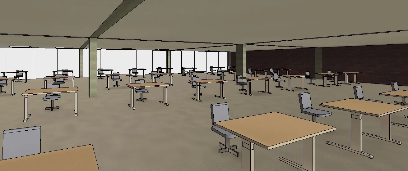
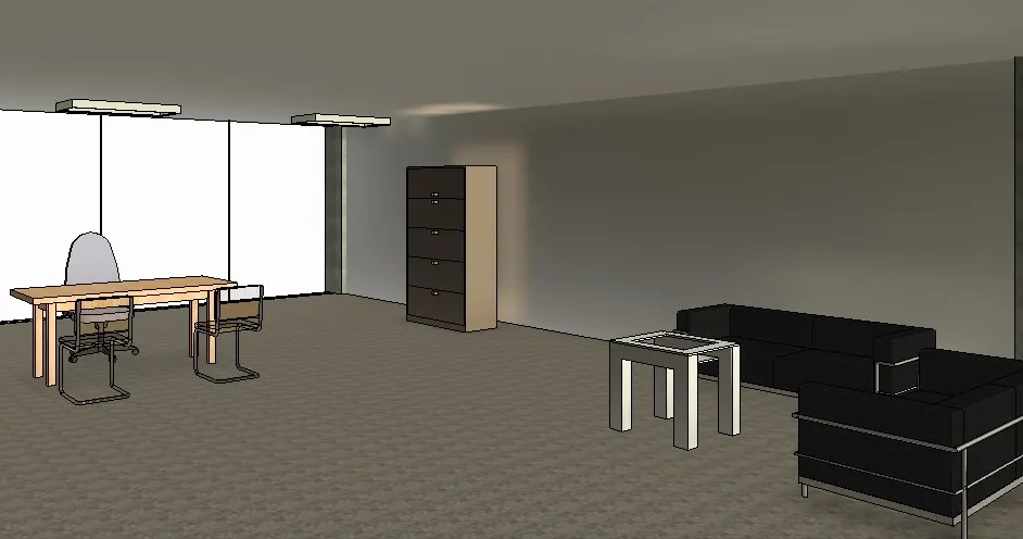
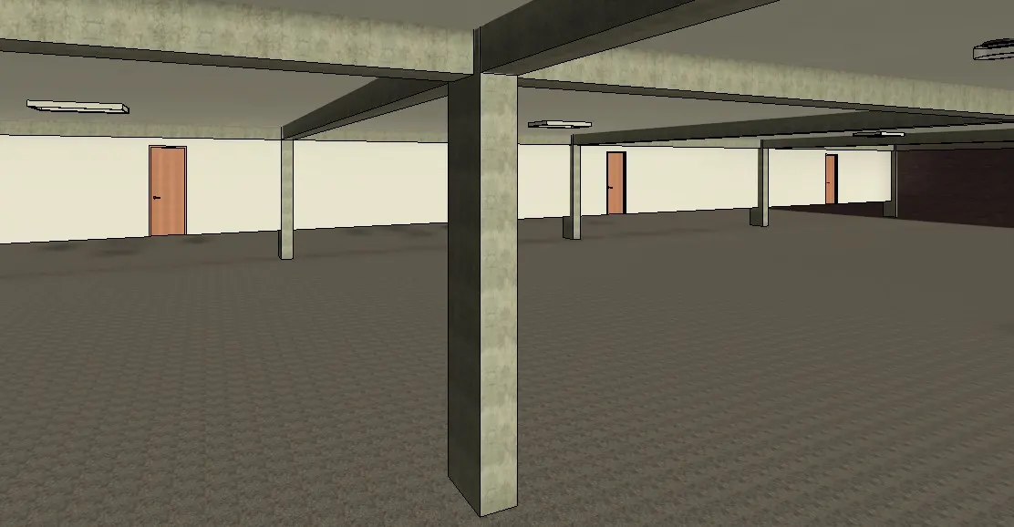
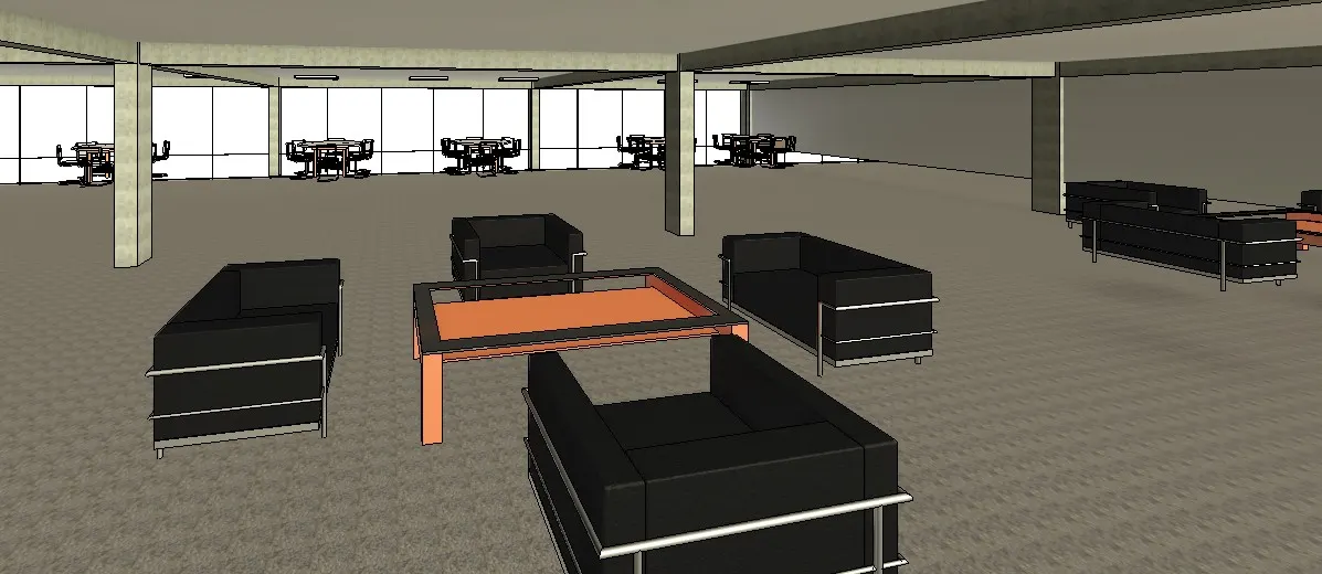
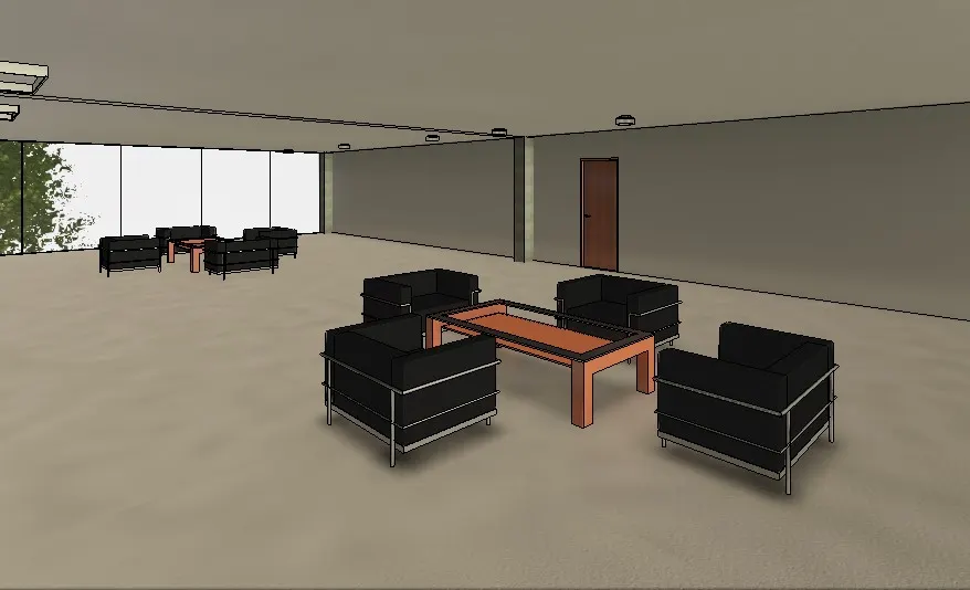
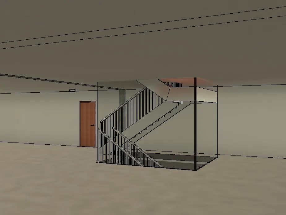
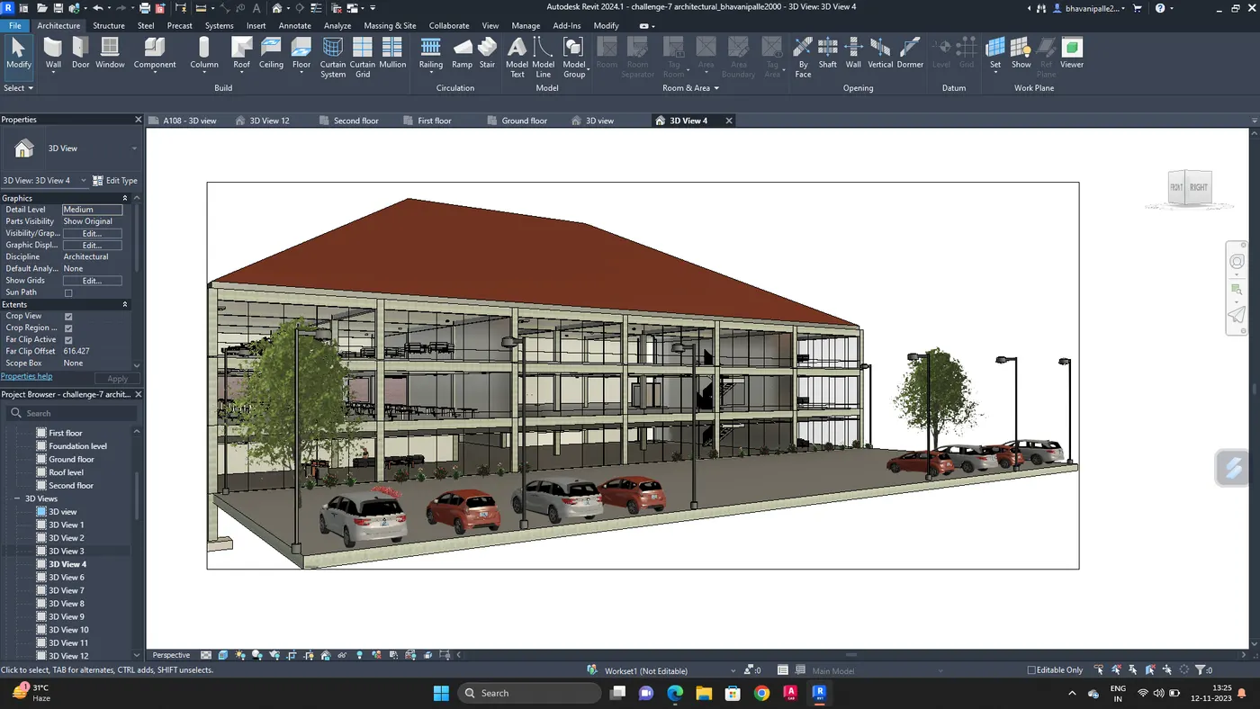
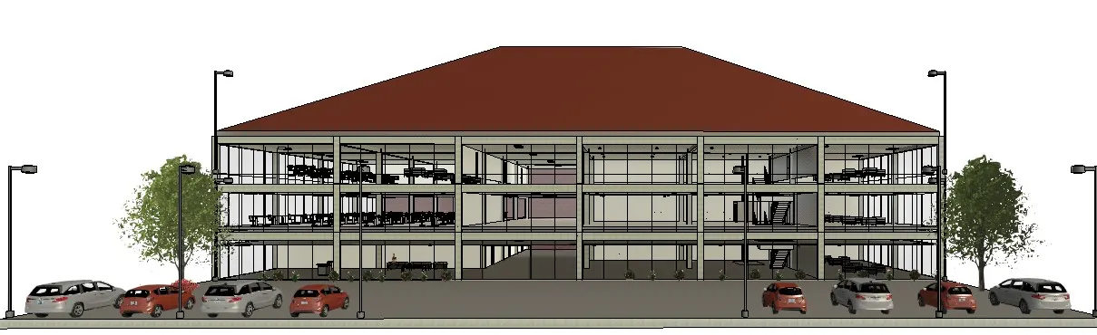
RESULT :
The views are rendered
7. AIM :
Print the set of drawing sheets created and submit the drawings from the architectural and structure model.
PROCEDURE :
Press Ctrl+p or
Go to application menu and select print

Select the appropriate settings,
Select the sheet or view and press ok.
RESULT :
The sheets are printed