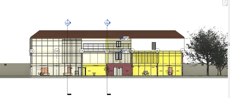
Creating Architectural and Structural model with 3D rendering using REVIT
1) Select the type of structure you want to build from one of the three below:
a. Multi-Unit Residential Apartment
b. Office Buildings
c. School
Aim:
- To Select the type of structure, want to Modelling using Revit.
Procedure:
- Schools' buildings have particular design requirements in terms of spatial planning and flexible use of space, control of vibrations and acoustics, and robustness.
- Class room sizes are specified in the department for education building bulletins, along with requirement for other large spaces such as specialist room and sport facilities.
- Steel construction has achieved a strong market share in all types of educational buildings for the above reasons.
- Modular construction has become the dominant form of construction for larger student residences.
Result:
- Therefore, type of structure is selected as school building for modelling in Revit software.
2) Assume reasonable assumptions for geographic and location details for your project modeling. Based on assumptions and type of structure selected identify the modeling requirements from NBC
Aim:
- School Building is constructed in the environmental and safety measures.
- In front of the construction there is a road of 30ft width.
- National building code provides the standards which should be followed while designing any type of model.
- For school building NBC provides the minimum standards for height, area, thickness of wall etc.,
- Assumed for geographic and location detailed constructed in the open area.
Result:
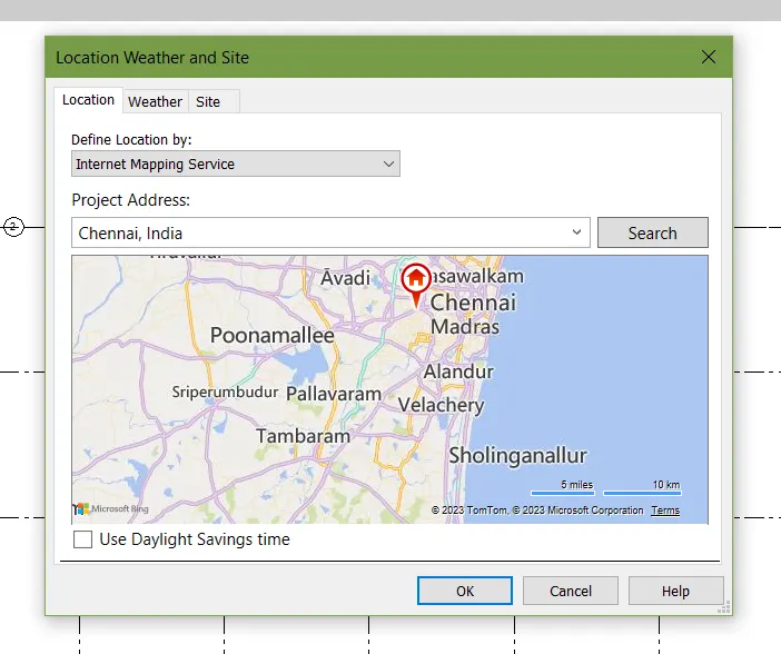
- Hence, location of building is assumed in Chennai India, and also based on assumption and type of structure selected modeling NBC guidelines Followed.
3) Using the structural model, include the following components based on the type of structure selected
a. Foundation – Isolated / Wall/Matt Foundation
b. Columns
c. Beams Connected to Columns
d. Roof Framing/ Truss
e. Floor / Decks
f. Floor Openings for Elevators and Stairs
Aim:
-
Using the structure model, based on the type of structure using structure model.
Introduction:
- A foundation is the lowest part of the building structure.
- Beams and columns are the main components to build the structure elements that play a key role in creating a safe load path to transfer the weight and for force a structure to the foundation and into the ground area.
- It is periphery of civil, structural and Geotechnical engineering disciplines and had distinct focus on soil structure interaction.
Procedure:
Step I:
- Open Revit software, select the structral template with the architectural created last week and open it from homepage of Revit software.
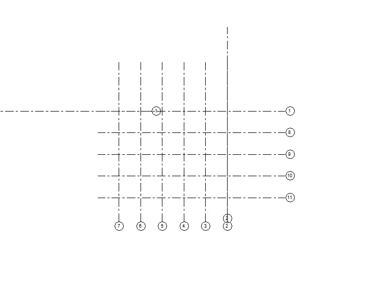
Step 2:
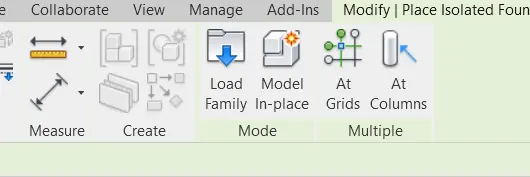
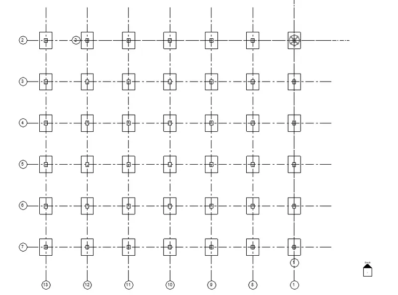
- Go to site plan view, select isolated footing from foundation panel of structure tab, select at grids option from place isolated foundation tab and select the grids by dragging the mouse and select finish from multiple and copy finish.
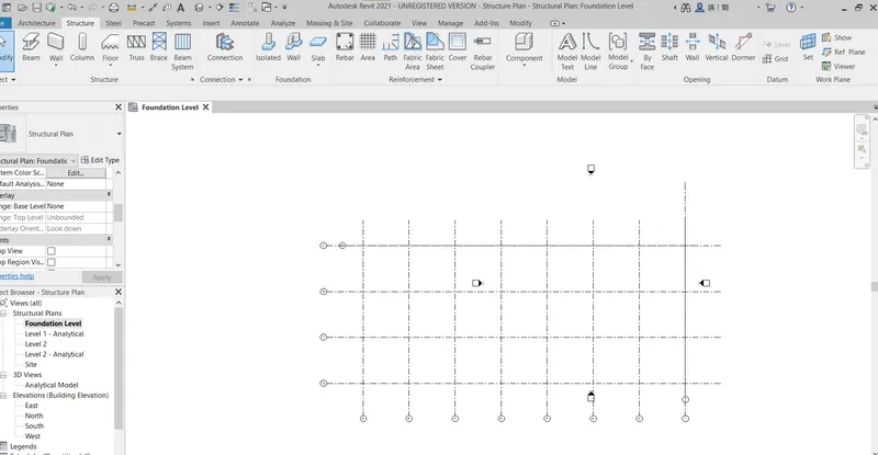
Step 3:
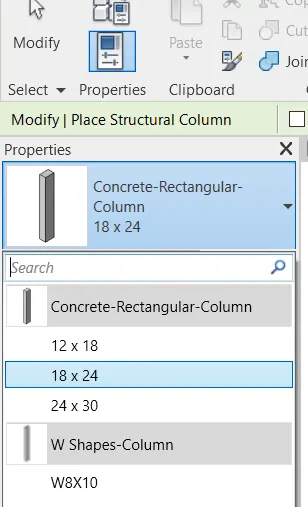
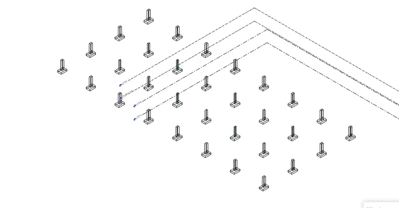
- For creating the columns go to column tool from structure tab, select the column type as concrete rectangular column of size 18 x 24 and change the depth of column as -5'0" from the properties tab.
Step 4:
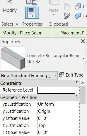
- Go to structure tab, select beam tool, select concrete beam from property window, select on grids option from place beam tab, select the grids by dragging with mouse and select finish from multiple panel.
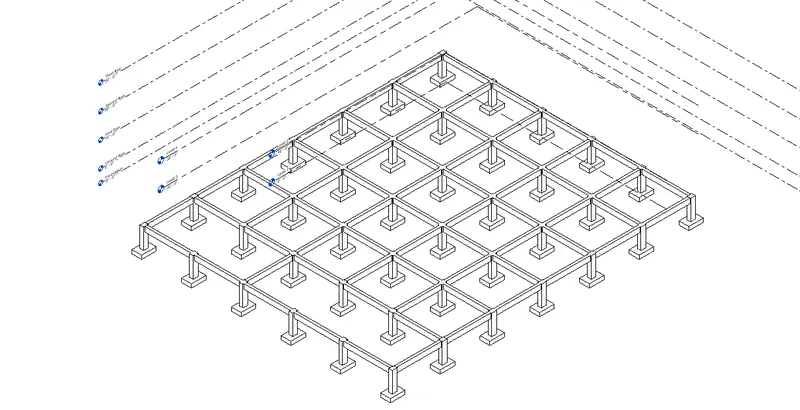
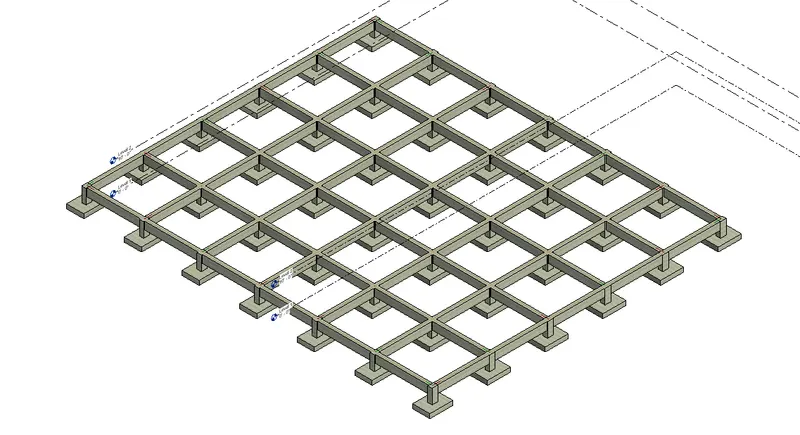
- 3D realistic view as shown below:
Step 5:
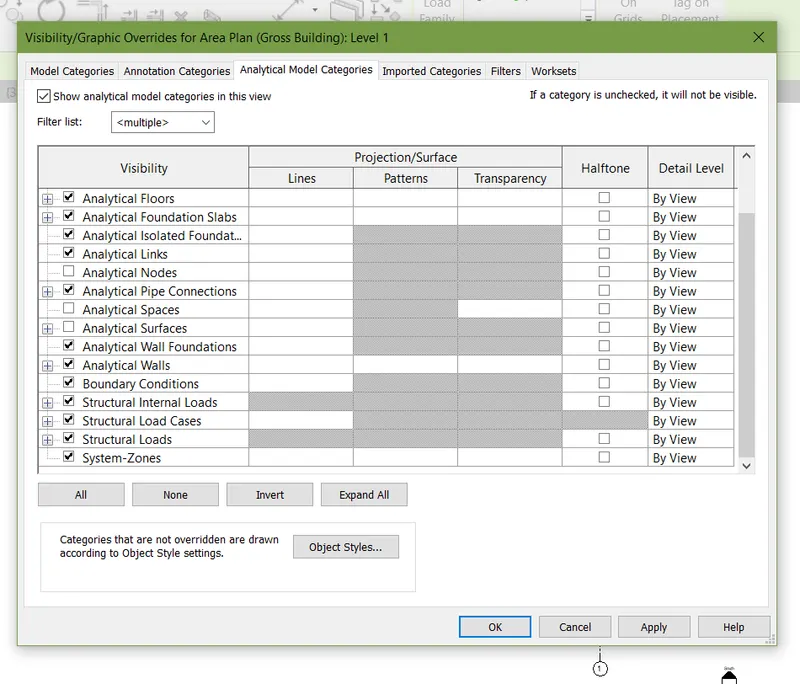
- Type VG command, uncheck all analytical model category visibilities from dialog box to hide analytical lines, select apply and ok.
Step 6:
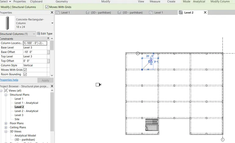
- Now Select all and using filter and create column at ground floor by selecting height option from modify toolbar of column and height up to first floor as figure shown below.
Step 7:
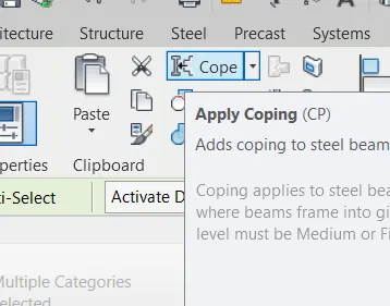
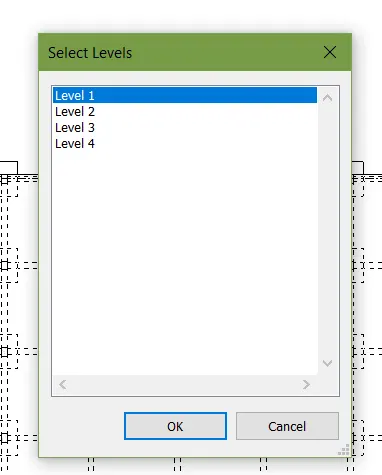
- To create the beams and column at the first floor to top floor select all components by selecting with the mouse, click filter tool, and select the structural column and framing from ribbon tab.
Step 8:
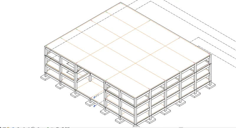
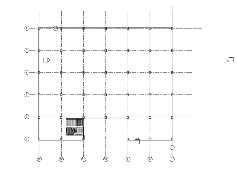
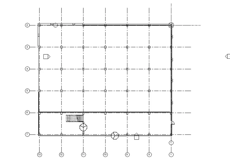
- Draw the floors, go to site floor plan view select the floor tool from structure tab, select rectangular tool from draw panel and create the roof as shown below the thickness of concrete as 3".
Step 9:
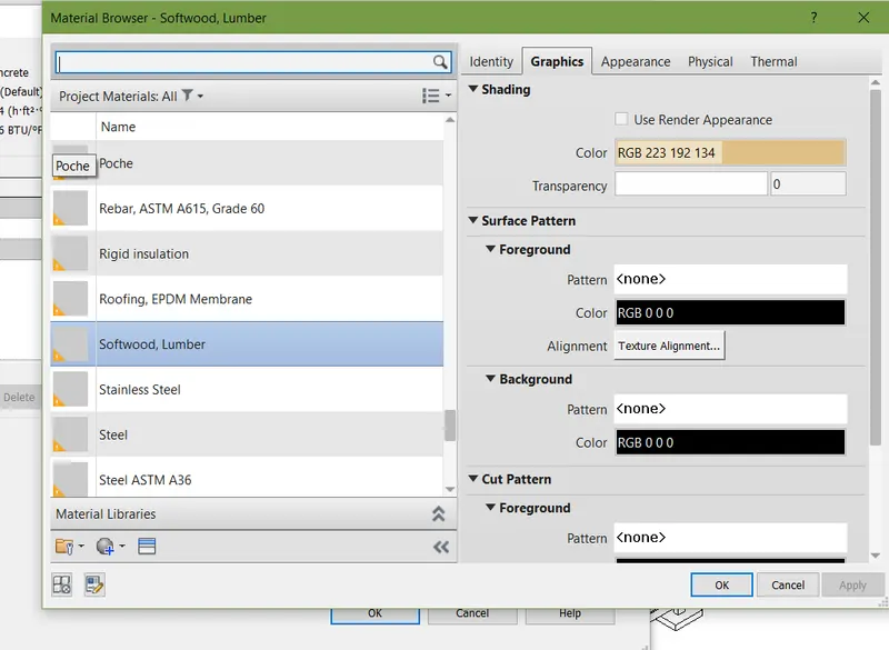
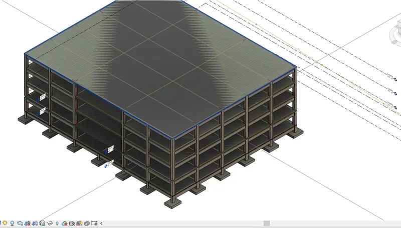
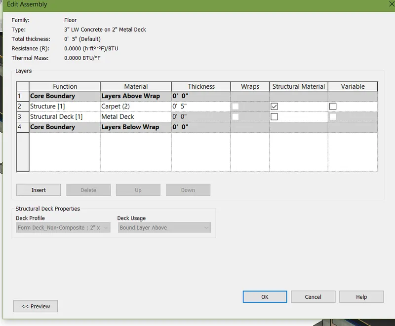
- Select the floor and select edit type from material property and change the floor carpet shown below.
Step 10:
- Select synchronize with central option from the toolbar and select ok.
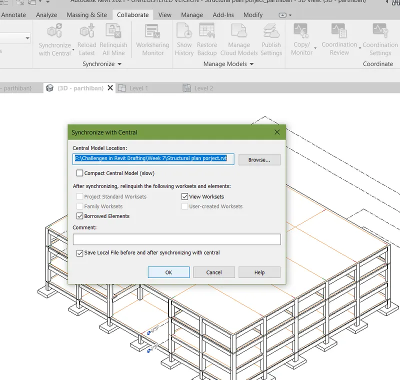
Result:
- The given components are successfully included based on the type of structure using the structural model.
4) Using the architectural model, include the following components based on the type of structure selected
a. Wall Layout with appropriate material and finishing
b. Exterior façade with fancy finish
c. Interior partition walls to size rooms
d. Components to add details to a room (Desk, Chair, Lighting, Plumbing fixtures)
e. Add components such as stairs Elevators
f. Have at-least one side of the building with curtain walls and glass panels
g. Include interior and exterior lighting fixtures
h. Place proper topographic components from outside (Trees, Parking, Plants) to add details to the model
Aim:
- To include the given components based on the type of structre selected using architectural model.
Introduction:
- Partition walls are a significant component of a building design.
- Without partition walls, a building plan cannot be decorated or structured.
- The most important function is as a holder for the light source, to provide directed light and to avoid visual glare.
- Revit is a BIM software where we can add minor details to make it more realstic to utilize or make more efficient space management without making any compromises in the future.
- Such as detailed may include Chairs, lighting and special equipment's etc.,
Procedure:
- Open the architectural file from the home tab.
- Select the walls tools from architecture tab, select wall type generic 12" from the property and create the walls at required position as shown below:
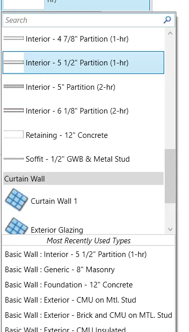
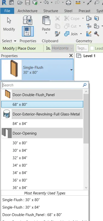
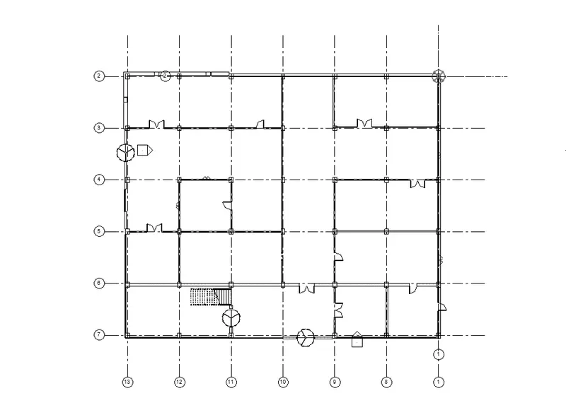
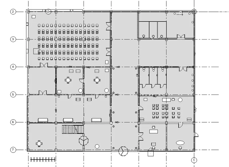
- For adding the components such as desk and required components go to architecture select the elements from build panel select load family option and load the materials and add it in the required model position as shown below.
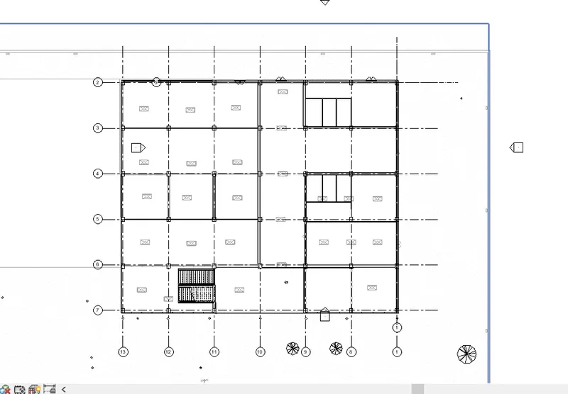
- Similarly add the First-floor plan up to third floor as figure shown below:
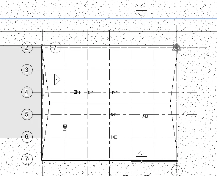
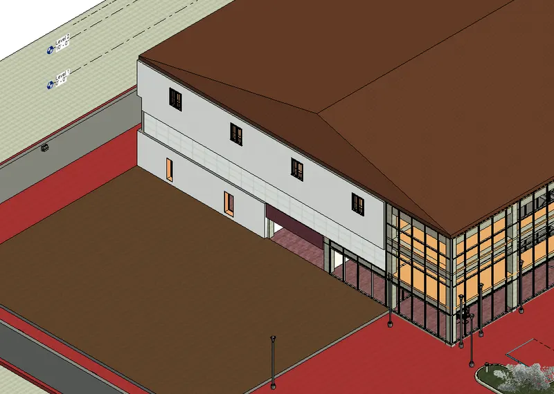
- For adding the roof, go to architecture tab, select the roof tool from panel, select roof by footprint select pick line or rectangle and draw the roof on the level four plan by specifying offset distance as shown below.
- Go to architecture tab, select the component option and load the site components such as tress and place at the required position.
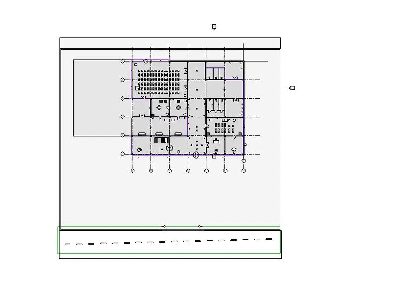
- Again, go to wall tool from architecture tab, select the wall type and draw the wall as a Shear wall, compound wall and insert gate opening and celling for all floors as shown below.
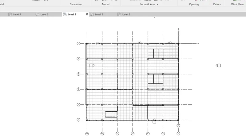
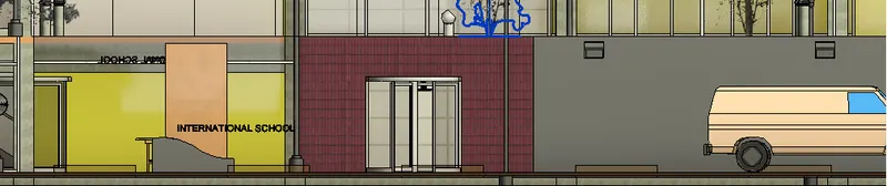
- Site level plan view.
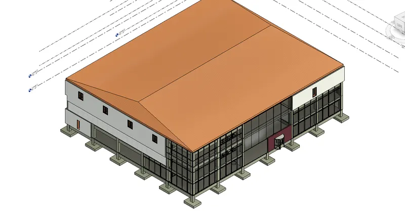
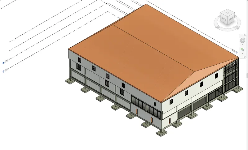
3D plan realstic views.

5) Provide a set of drawings in an architectural and structural model to list the following details with categories and appropriate sheet templates included
a. Floor Plans with Annotations
b. Elevations
c. Sections
Aim:
- To provide a set of drawings in an architectural and structrual model to list the given details with categories and appropirate sheet templates included.
Introduction:
- Floor plans are the most critical element of your house plans.
- Drawn to scale and shown from above, floor plans illustrate how rooms, spaces and physical features work in relation to each other within the home.
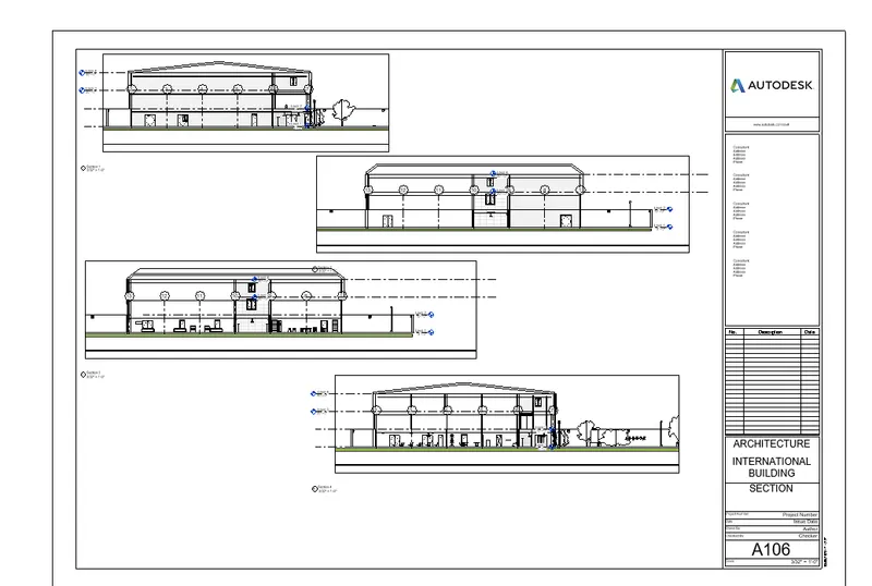
- Section views reveal hidden details in a mechanical drawing.
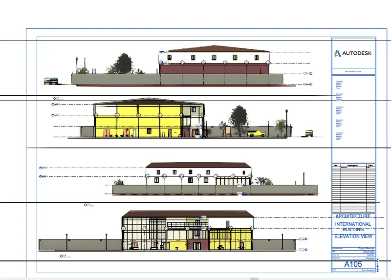
- Each elevation is labelled in relation to the compass direction it faces, e.g., looking towards the north you would be seeing the south elevation of the building.
- In Revit dimensions of lines are measured with help of the aligned or horizontal tool of the annotate tab.
Procedure:
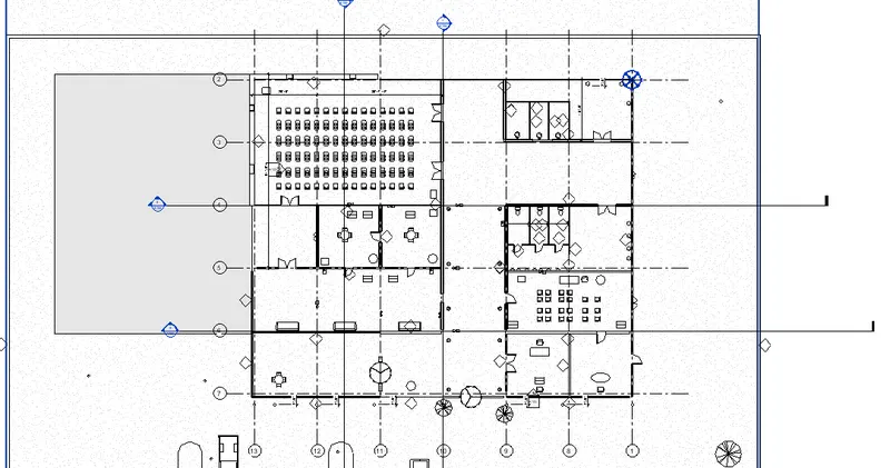
- First, we add the ground floor plan to the sheet, as shown below.
- Open architecture template file to give annotation
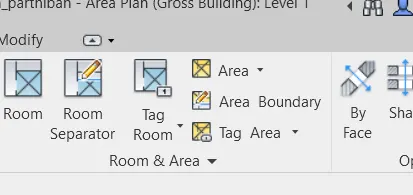
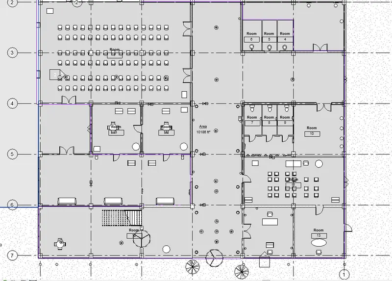
- Similarly go to room tool from room area panel in architecture tab, and give room tags to each room as shown below.
- For creating the section view go to view tab selection tool of section and create the section at the required position as shown below.
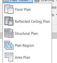
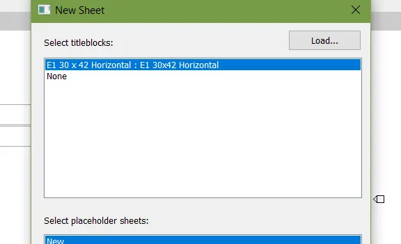
- Select the sheet paper size as E1 30x 42 horizontal and select of from dialog box, it will open the created sheet template.

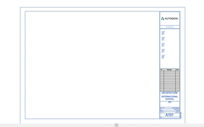
- For adding the floor plans in the view, select the view from project browser and drag the view into sheet as shown below
- Adjust the scale of view as per requirement scales.
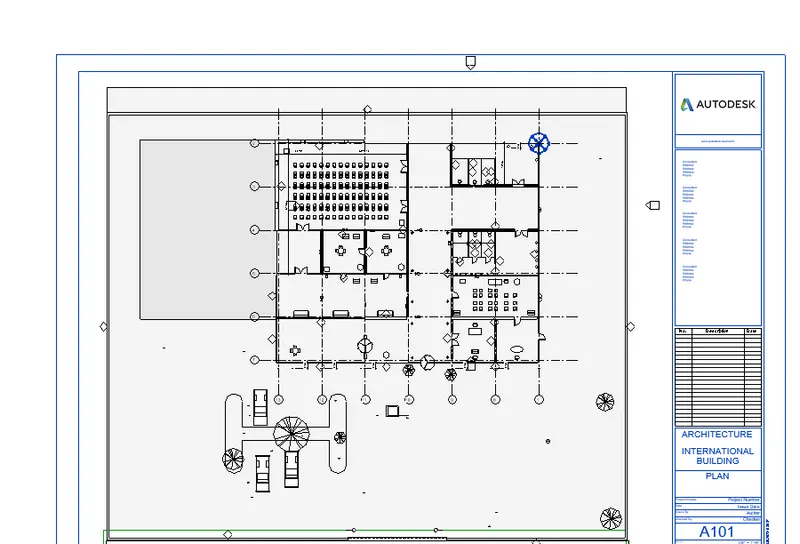
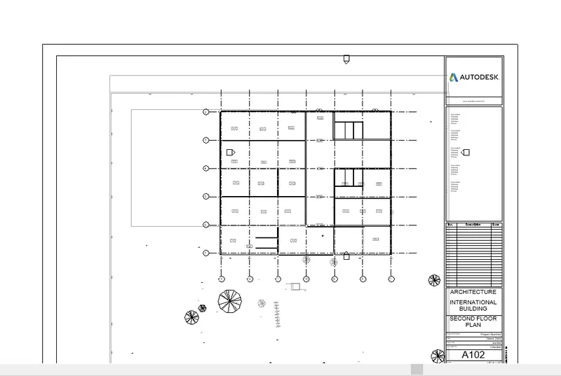
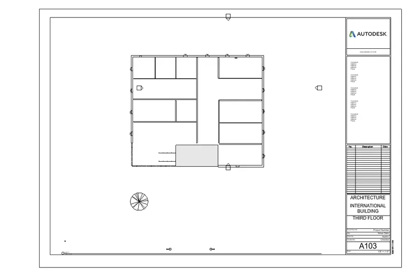
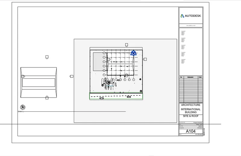
- For adding elevation views in the sheet select elevation view from project browser and drag the view into the sheet after creating new sheet using tool of view tab.
- Similarly insert the section view into new sheet by dragging the views from the project browser as shown below
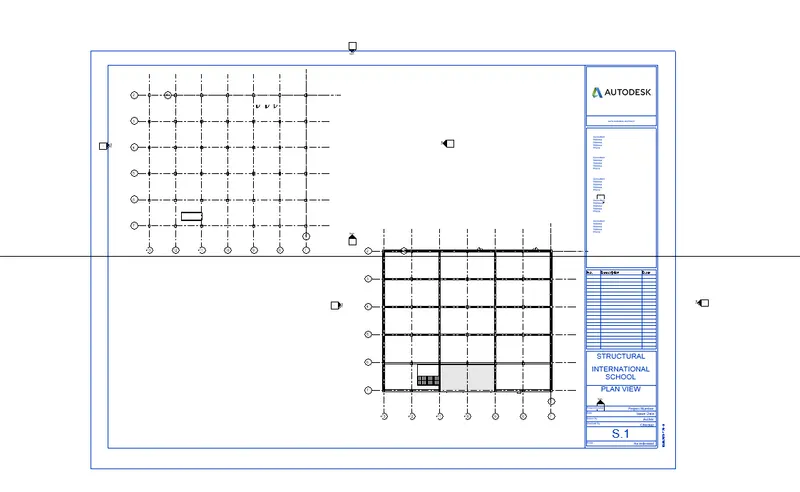
- Now go to structure template.
- open the file for created structural plan
- Next select the first floor and select ok from the new structural plan then plan view as created as shown below.
Result;
- Provided a set of drawings in a architectural and structural model and listed the given details with categories and appropriate sheet templates included.
6) Using the Rendering settings, Render images of the 3D model produced and include the rendered images to the drawing sheets
a. Rendering from interior rooms
b. Rendering from out showing topographic features
c. Rendering through structural framing
- Rendering through structural framing
Aim:
- To use the rendering settings to render a 3D model produced and include the rendered images to drawing sheets.
Procedure:
- Open Revit software go to architectural file.
- Go to the view tab and select the camera option. And drag the camera view to set room view.
- After placing the camera in the room, then use rendered images.
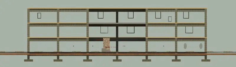
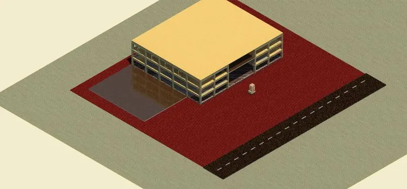
- And also create a rendering image in structural framing from the structure model.
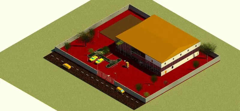
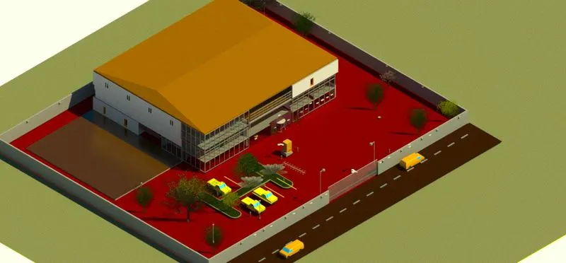
Rendering view from out showing topographic features:

Rendering through structural framing:
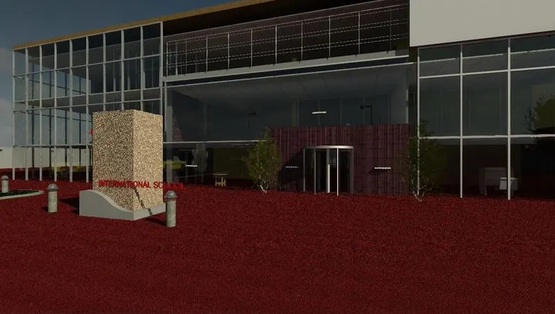
Placing the cameras and rendering the views of rooms:
1. Entrance of the school:
2. Auditorium
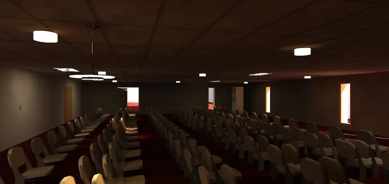
3.Class Rooms
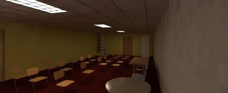
4. Front office
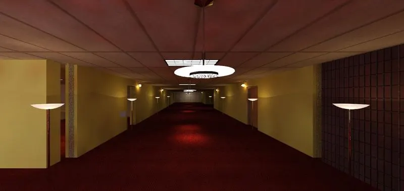
6. Reception Area
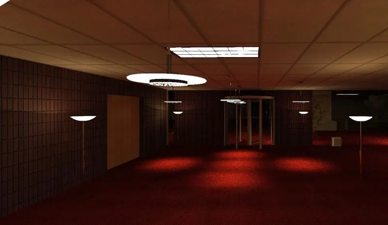
7. Library
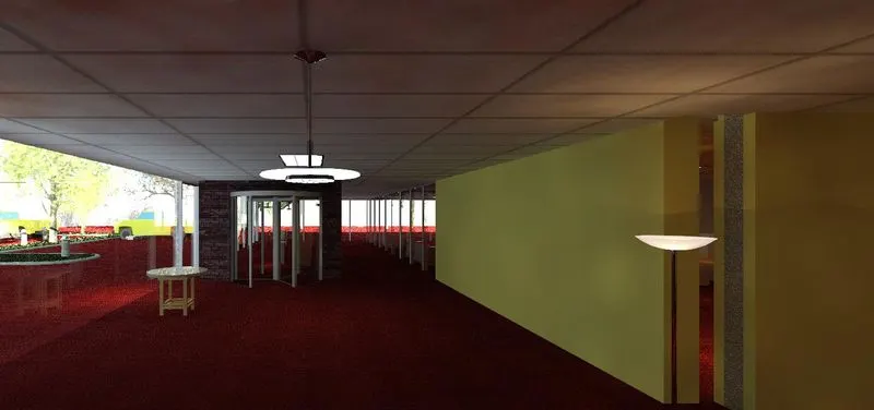
8. Parking Lot
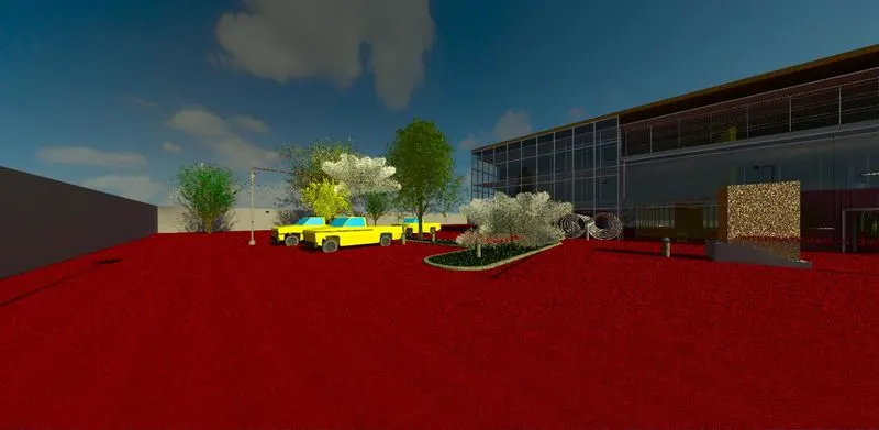
9. Play Area
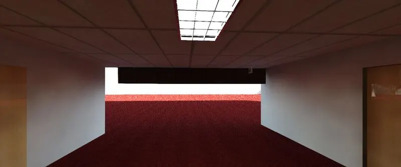
10. Staff rooms
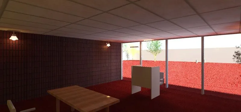
11. Toilet
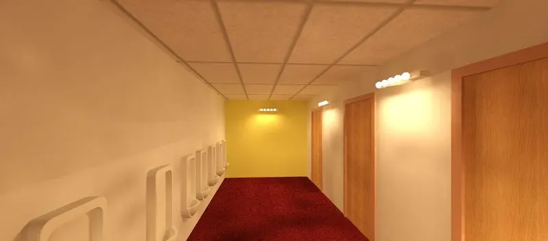
12. Waiting hall
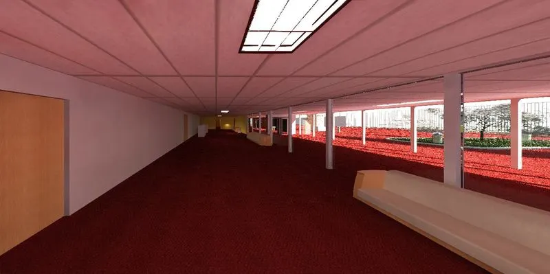
7) Print the set of drawing sheets created and submit the drawings from the architecture and structure model
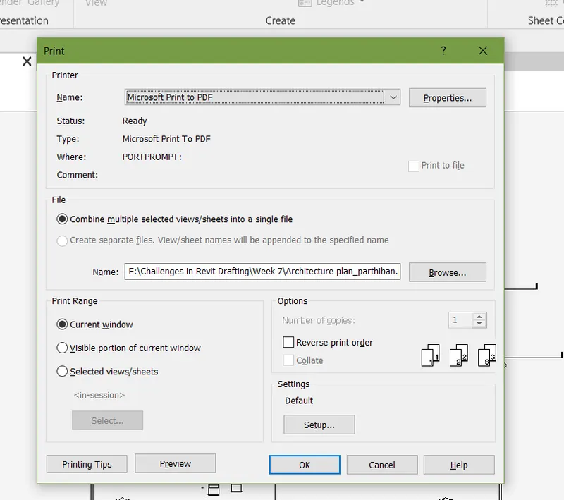
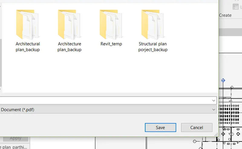
- To print or save model in the pdf format of the drawing for the paper sizes.
- Use the key CTRL+P shortcut.
- Select the view and set it to be as print or save format.
- Choose the number of copies in Revit software.
- Finally press ok, as following figure shown below as;
Result: