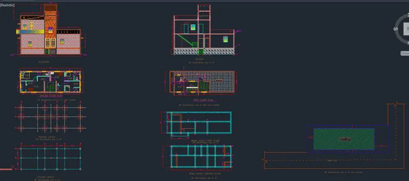
Project 1 _Creating an Architectural plan for the provided plot size and develop relevant basic structural drawings
Aim:
To design and draft the layout of a residential building of plot size 60' x 20' (18.3m x 6m) facing east.
Develop architectural drawings such as floor plan, elevations, sections and develop structural drawings such as column, beam, footing.
Introduction:
A residential building of G+1 is sketched in the given plot size 60' x 20' east facing.
The built-up area of the plot is 1200 sq ft.
The ground floor consists of a 2-living room, 3 bedrooms, 2 kitchens, a pooja room, 2 main doors entrance and parking.
The first floor consists of utility area, 1 bedroom, balcony, overhead tank and open terrace floor.
Objectives:
1. The objective of this project is to sketch floor plans such as Ground Floor, First Floor and Open terrace.
2. To sketch the structural drawing such as column layout, footing layout and beam layout.
Ground Floor Plan Details:
Section 1: -
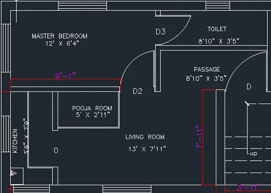
- Master bedroom - 12' x 6'4"
- Living Room - 13' x 7'11"
- Toilet - 8'10" x 3'5"
- Kitchen - 3'6" x 7'9"
- Pooja Room - 5' x 2'11"
- Passage area -8'10" x 3'5"
Section 2: -
- Living Room - 9'10" x 9'9"
- Kitchen - 5'7" x 4'4"
- Guest Room - 11' x 7'9"
- Bed Room - 6'7" x 6'4"
- Toilet - 4' x 6'4"
- Bath - 4' x 3'5"
First Floor Plan Details: -
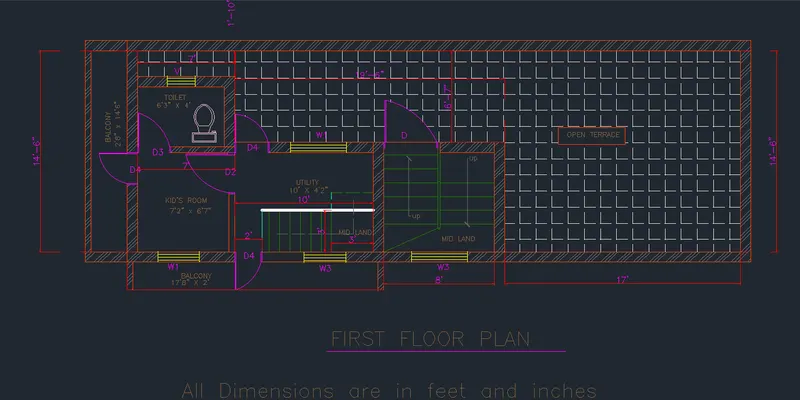
- Utility Area - 10' x 4'2"
- Bed Room - 7'2" x 6'7"
- Toilet - 6'3" x 4'
- Balcony South side - 2'8" x 14'6"
- Balcony East side - 71'8" x 2'
- Open Terrace.
Wall Details:
- Exterior Wall - 9"
- Interior Wall - 4.5"
Door and Window Details:
- D1 - 3'6" X 7'
- D2 - 3' X 7'
- D3 - 2'6" X 7'
- D4 - 2' X 7'
- W1 - 4' X 4'
- W2 - 3' X 4'
- W3 - 4' X 5'
- V - 2' X 2'
Staircase Details:
- Raise - 6"
- Thread - 9"
Structural Element Details:
- Footing - 3' x 3'
- Column - 9" x 9" and 1' x 9"
- Plinth Beam - 1' x 9"
- First Floor Beam - 1' x 9"
- Slab Thickness - 6"
Procedure: -
. Open the Auto-cad select a new file to start the project.
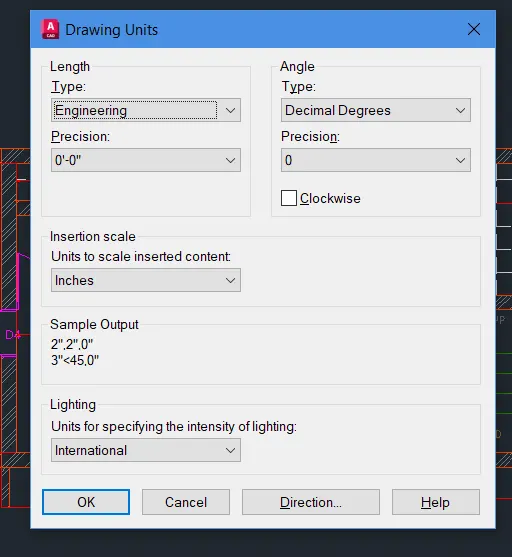
. Set the units as inches, type has Engineering and as precision as 0.
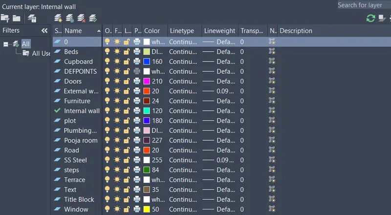
Create the New layer that is used in project. Type Command has LA to create the New Layer.
Architectural Drawing: -
1. Plan of the Residential Building: -
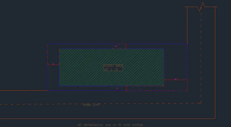
- Direction of Plot is East Facing.
- The Plot dimensions as 60' and 20'
- Give set back from the Plot Front from the East side 2', West side 2', North side 10' and South side 5'
- The proposed Building should come inside the setback Drawn.
2. Ground Floor Plan: -
- Set the View direction as east Facing by clicking the arrow cube.
- Change the UCS as x-axis facing in north and Y-axis facing in west.

- Draw the line with the command of XL vertical and horizontal lines.
- Offset to 45'in X-axis and 16' in Y-axis.
- Offset 9" From the Exterior wall in all sides.
- Clear the unwanted lines with the help of Trim command.

- As the orientation is given as Main door Entrance should face in East.
- Take offset Vertical line as 17' towards North Direction. Construction line next to next as 9",8',9",17'.
- Again, offset the Horizontal line as 7'11" towards West direction. Construction line next to offset as 4.5"
- As per Vasthi Shastra Master Bed room in South west side and Kitchen in South East and the Living room and the Entrance should face North or East.
- Opening for Main door is Create by offset from 17'9"wall in vertical 3'6" and center wall thickness as 9".
- Create the outer staircase from Easten exterior wall in the middle of 3'11"take an offset of 1' for the 1st flight.
- Rise - 6"
- Thread - 1'
- Total no of steps - 4 steps.
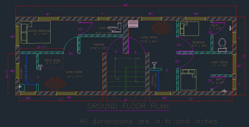
- Take offset for another entrance 3'6" for door. and create rooms.
- For living room 9'10" x 9'9"
- Kitchen 5'7" x 4'4"
- Bed room 6'7" x 6'4"
- Toilet 4' x 6'4"
- Guest room 11' x 7'9"
- Bath 4' x 3'5"
- Place the Doors and windows in the required places.
- Make cutouts in the kitchen and pooja room in the area walls.
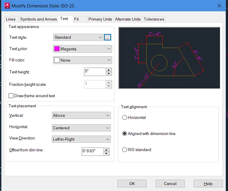
- Set the text style as simplex. shx by using dims in the command line.
3. First Floor Plan: -
- Turn off the dimension layer and text layer by opening the layer properties manager.
- copy the ground floor plan and place for the help of ortho on.
- Remove the walls in section 2 walls. to form the terrace.
- Then the living room changes to raise the interior flight from ground to first floor.
- Create a kid's bedroom by offset of left side wall and the distance of 7'2' X 6'7" and offset in 4'5"
- Create a toilet in the kids' room by offset the west side wall 4' and north side wall as 6'3"
- Enter the command of offset from exterior wall of south side 2'8" for balcony.
- Again, offset from exterior walls of east side 2' for balcony for section 1.
- Then create a parapet wall in the outer areas it will become terrace in the first floor.
- From the first-floor flight to the top floor. construct the overhead tank respectively.
- Create a text to specify the room names and sizes by using 'MT' multiline text command.
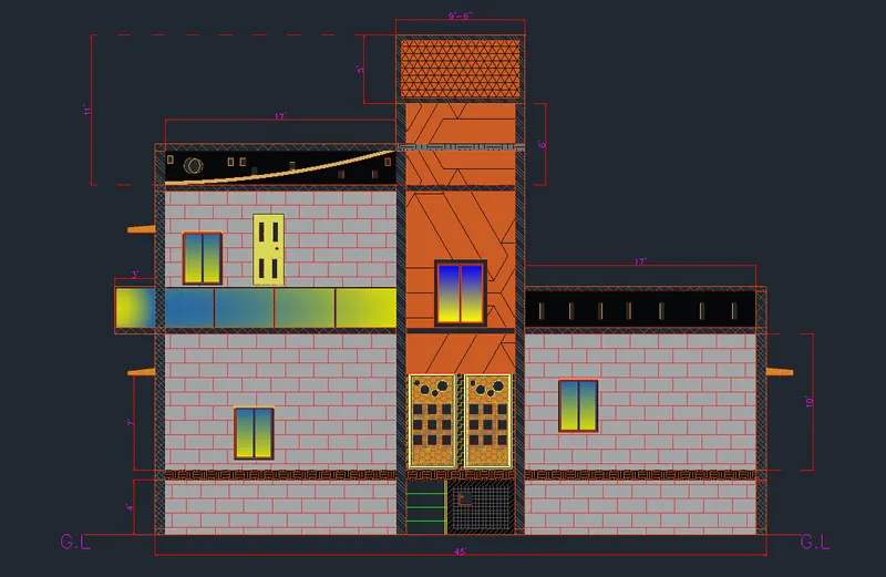
4. Elevation: -
- Project the wall lines to the top.
- Draw horizontal line
- Offset 4' for the Basement level
- Offset 1' for the plinth level.
- 7' Offset for the lintel level.
- 3' offset for the Ground floor level.
- 6" offset for slab.
- As per same as to first-floor
- Trim the left side walls to open Terrace.
- Raise the Staircase column lines from the First floor for Generator room.
- And overhead tank for 9'6" x 5'.
Doors and Windows: -
- For windows and doors project the window from the plan.
- For window W1 in 3' x 4' and W3 in 4' x 5'
- Project of doors and give a height 7'
- Project the shades and draw the shade at top of the window level.
- Trim of the extension lines and make shutters and panels for doors and windows
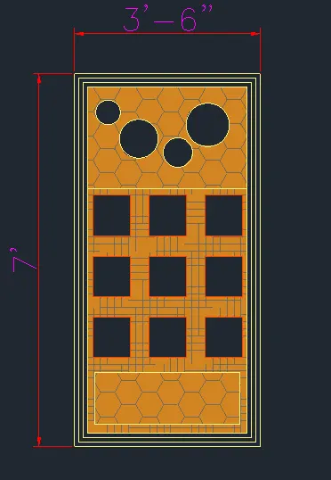
- For D1 entrance door create a rectangle offset 1" three times for thickness join the corners by line.
- Draw small rectangle and array for 3 Rows and 3 Columns.
- Create small circles on your own.
- Hatch the inner rectangle name of honeycomb.
-
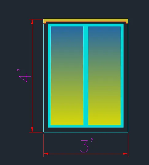
For windows W1 height 4' draw offset of1" for the thickness.
-
Draw a rectangle offset from the frame also thickness of 2"
-
Give shade at the top of the window.
-
used a hatch solid pattern to the window.
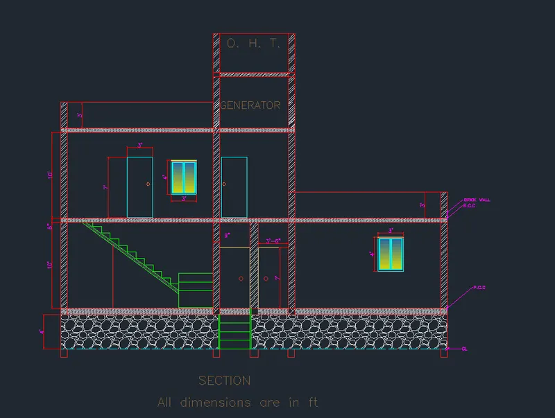
5. Section: -
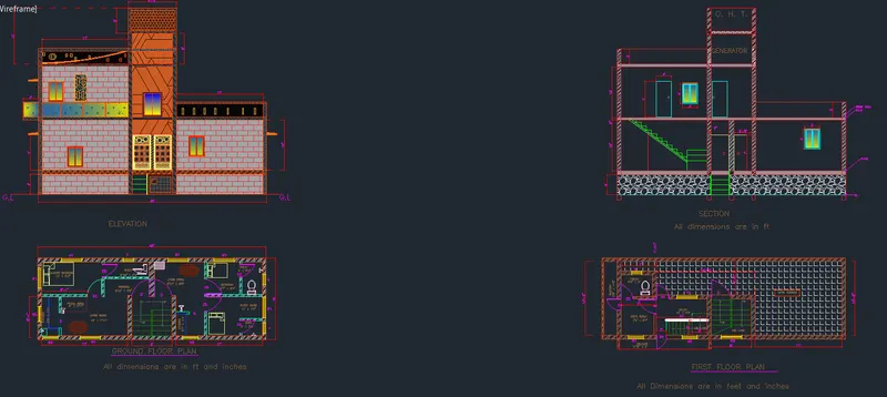
- Section of ground floor and First Floor.
Procedure: -
- Take the reference line of Ground floor plan vertically
- Command L for Line
- Make Line over horizontally and vertically
- Command offset for Brick walls 9"
- Then make PCC line and hatch it
- Use multileader for mention the categories
- Create steps in left side ground to first floor flight
- Slab of thickness 6"
- Make door frames in each entrance
- make windows by projecting from first floor plan
- Project the generator room
- Projecting O.H.T. area.
- parapet walls are in 3' height
- Dimensions all are in feet and inches.
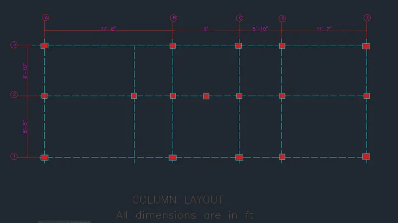
6. Column Layout Plan: -
- Command Used;
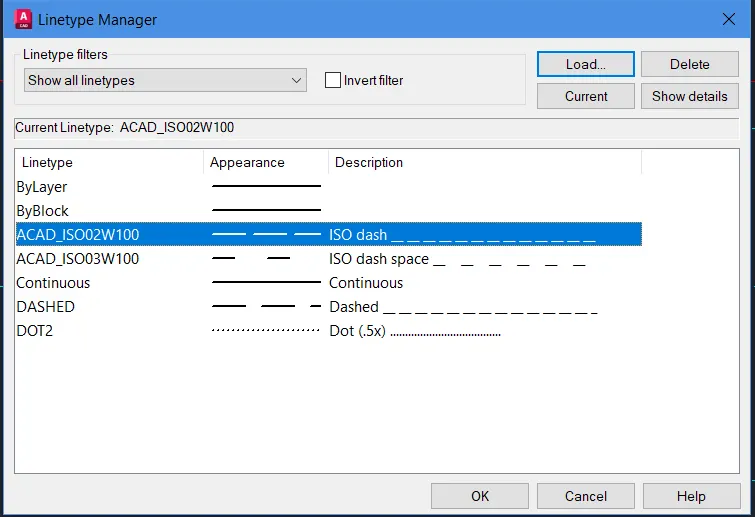
- Line type
- Offset
- midpoint
- centerline
- Q leader
- hatch
- M text
- Dim linear
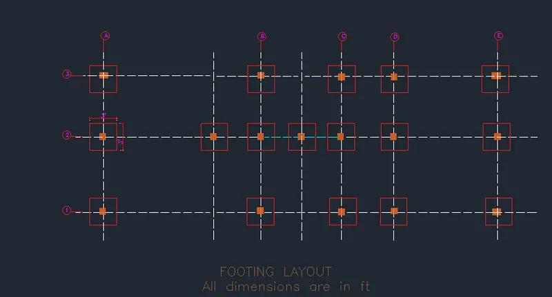
7. Footing Layout Plan: -
- Command Used;
- Line
- Offset
- Trim
- Rectangle
- M Text
- Dim linear
- Extend
- Hatch
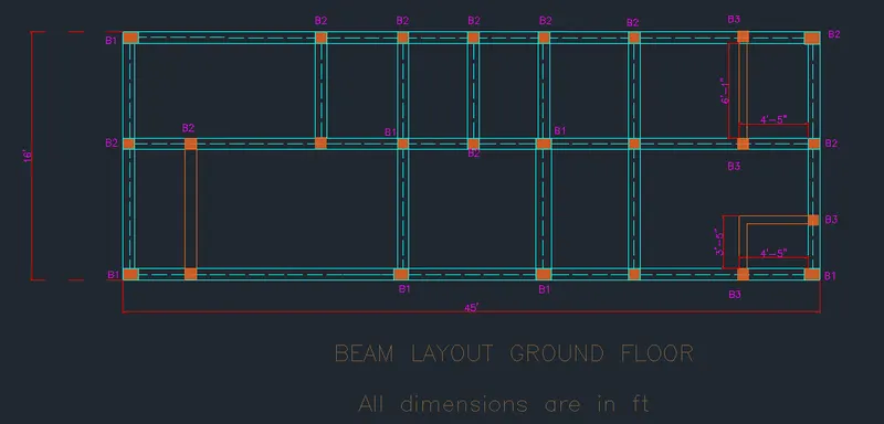
8. Ground Floor Beam Layout: -
- The Drawing of layout of Ground Floor Beam using AUTOCAD software by using above mentioned procedure is shown below.
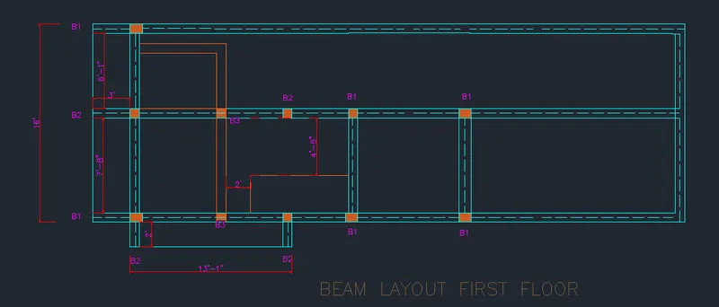
9. First Floor Beam Layout: -
- The Drawing of layout of Ground Floor Beam using AUTOCAD software by using above mentioned procedure is shown below.
RESULT: