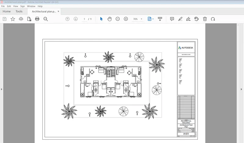
Creating Architectural and Structural model with 3D rendering using REVIT
QUESTION: Creating Architectural and Structural model with 3D rendering using REVIT
AIM:
To creating Architectural and Structural model with 3D rendering using REVIT
INTRODUCTION:
Revit is a commercial building information modeling (BIM)software by the company Autodesk. Its generally used by architects, structural engineers, mechanical, electrical and plumbing (MEP) engineers, designers and contractors. Autodesk Revit allows users to create, edit and review 3D models in exceptional detail.
Architects:
- Real time/3d
- Better coordination for projects
- Huge data and library to give shape to ideas
Structural engineers:
- Engineering design of the conceptual design
- Real time coordination
- Optimization of design
PROCEDURE:
1) Select the type of structure you want to build from one of the three below:
a. Multi-Unit Residential Apartment
b. Office Buildings
c. School
I have selected to build a design of Multi-Unit residential Apartment
2) Assume reasonable assumptions for geographic and location details for your project modeling. Based on assumptions and type of structure selected identify the modeling requirements from NBC
- My model is constructed in residential area tambaram, chennai
- My model is constructed in plain geographic area
- As per the NBC, the height limit will be given in NBC (National building code)
- The size of the rooms also given in the NBC
3) Using the structural model, include the following components based on the type of structure selected
a. Foundation – Isolated / Wall/Matt Foundation
b. Columns
c. Beams Connected to Columns
d. Roof Framing/ Truss
e. Floor / Decks
f. Floor Openings for Elevators and Stairs
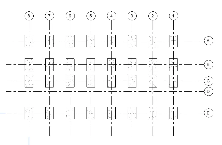
Step 1: Foundation
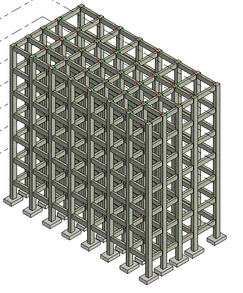
- First we create the grid lines longitudinal and transverse
- Select isolated founadtion click the selecting grid line option and drag to select all grids
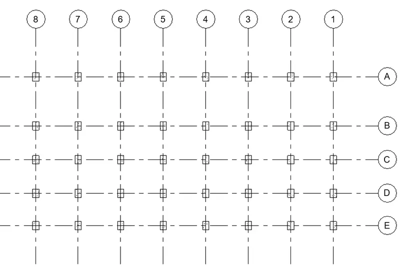
Step 2: Columns
- The above same procedure to create columns, here we select columns in structure tab
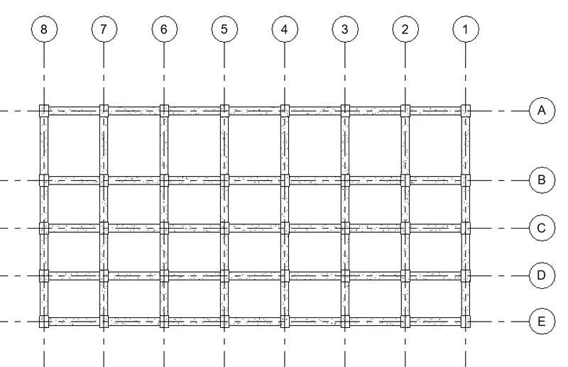
Step 3: Beams connected to columns
- The same procedure to follow to create the beam
Step 4: Floor and Roof
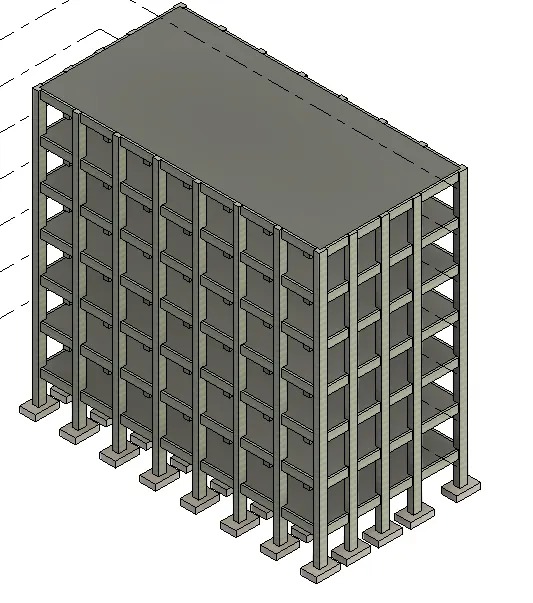
- Floor can be created each level
- Roof created on te top level
Step 5: Floor openings for stairs and lift
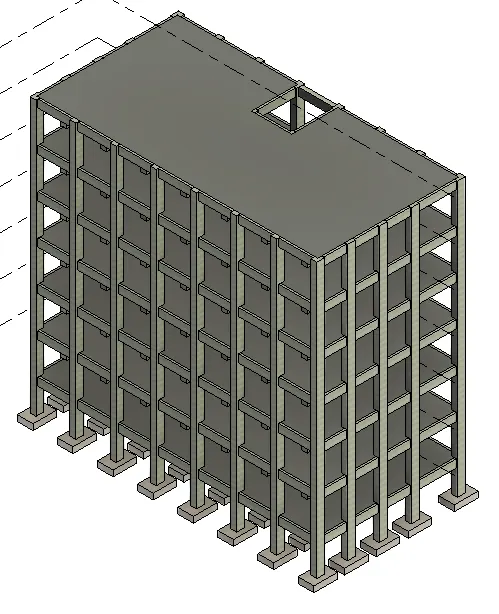
- Using shaft option to create the openings
Result:
4) Using the architectural model, include the following components based on the type of structure selected
a. Wall Layout with appropriate material and finishing
b. Exterior façade with fancy finish
c. Interior partition walls to size rooms
d. Components to add details to a room ( Desk, Chair, Lighting, Plumbing fixtures)
e. Add components such as stairs Elevators
f. Have at-least one side of the building with curtain walls and glass panels
g. Include interior and exterior lighting fixtures
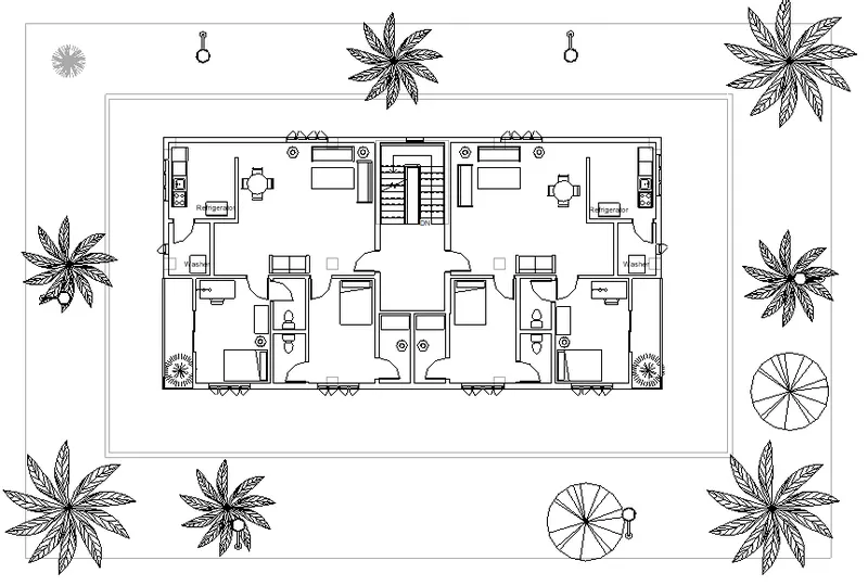
h. Place proper topographic components from outside ( Trees, Parking, Plants) to add details to the model
Step 1:
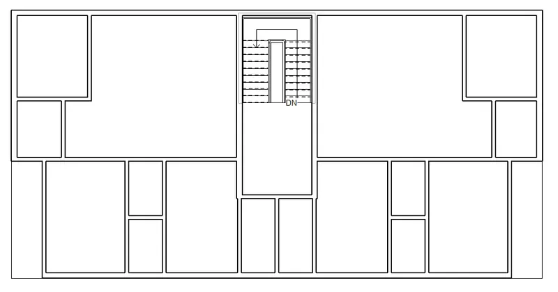
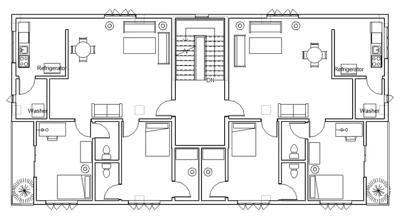
- Create the architectural plan
Step 2:
- Place the doors and windows from the family
- Place the diferrent components at desired place
Step 3:
- Create the ceiling and fix the lightings
Step 4:
- Create the extra massive component
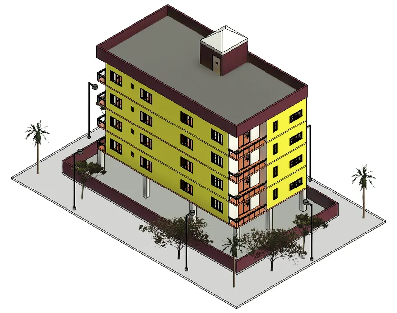
Result:
5) Provide a set of drawings in an architectural and structural model to list the following details with categories and appropriate sheet templates included
a. Floor Plans with Annotations
b. Elevations
c. Sections
Step 1: Floor Plans
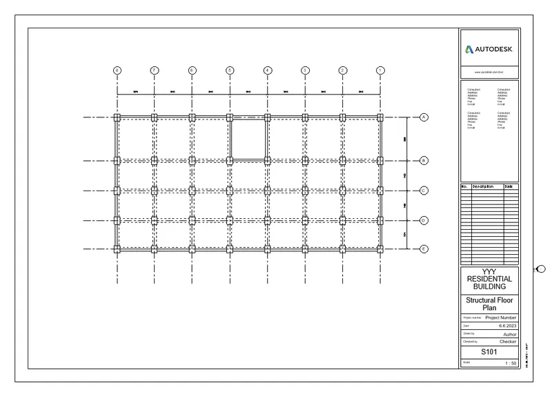
- Structural Floor Plan
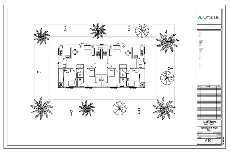
- Architectural Floor Plan
Step 2: Elevations
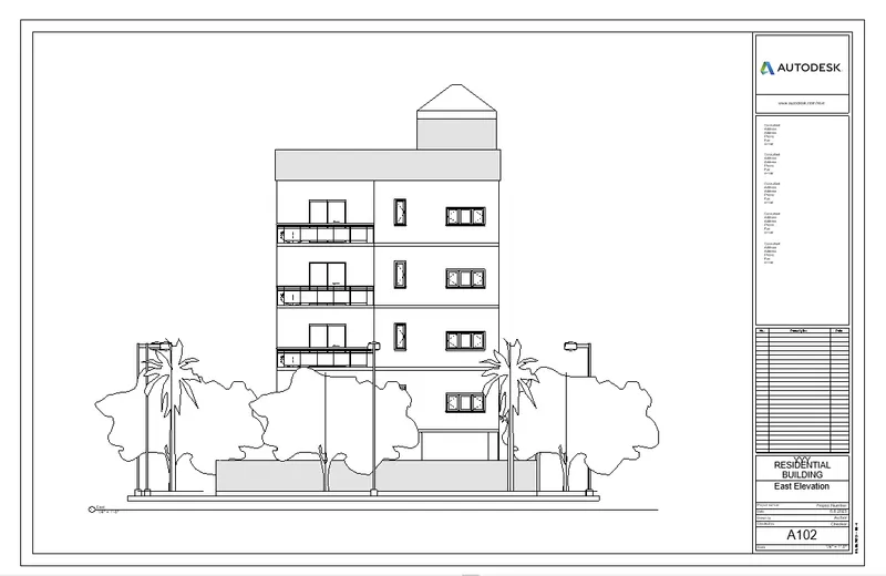
- East Elevation
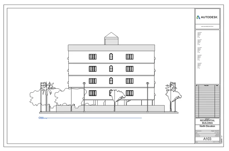
- North Elevation
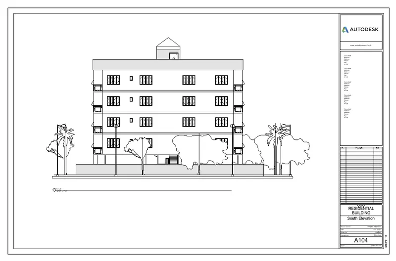
- South Elevation
- West Elevation
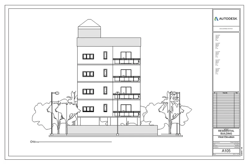
Step 3: Sections
- Section 01
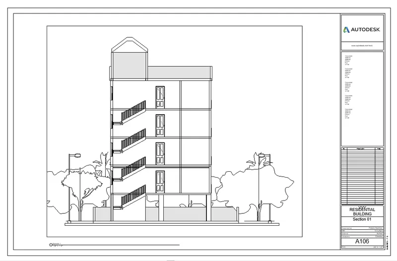
- Section 02
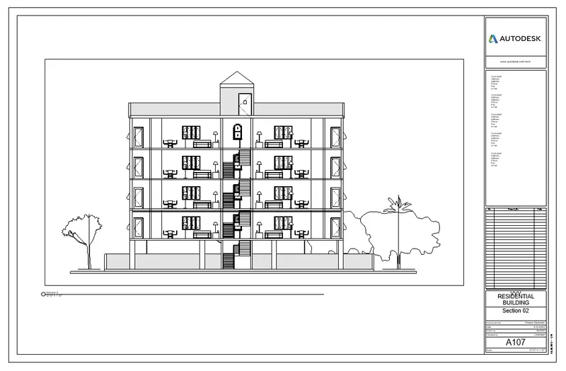
Result:
The Structural plan, Architectural plan, Elevation plans. Section plans are added sucessfully in appropriate sheet template.
6) Using the Rendering settings, Render images of the 3D model produced and include the rendered images to the drawing sheets
a. Rendering from interior rooms
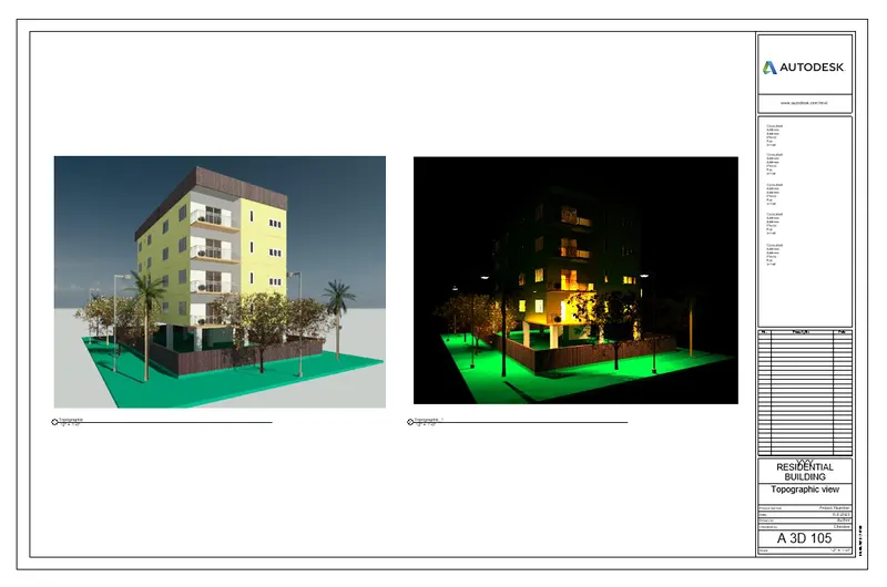
b. Rendering from out showing topographic features
c. Rendering through structural framing
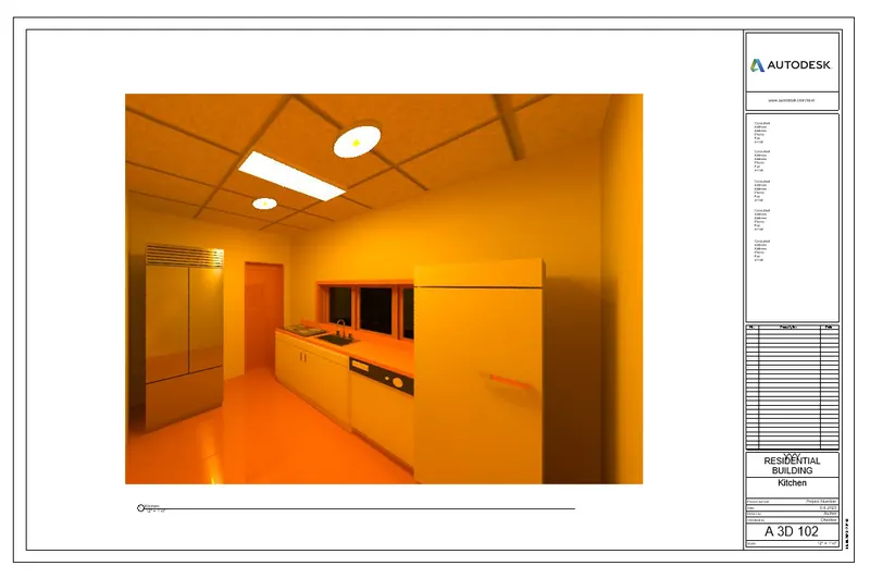
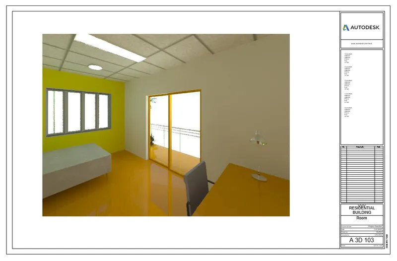
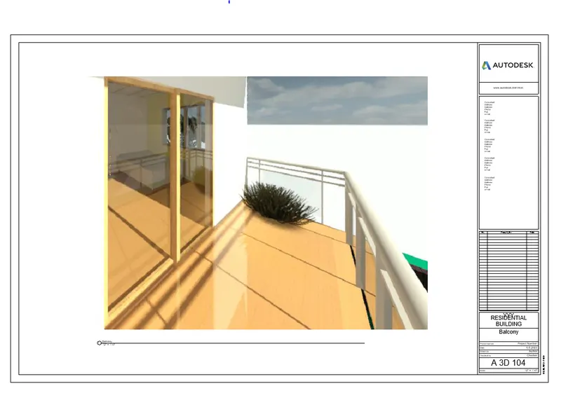
Step 1: Rendering from interior rooms
- Hall
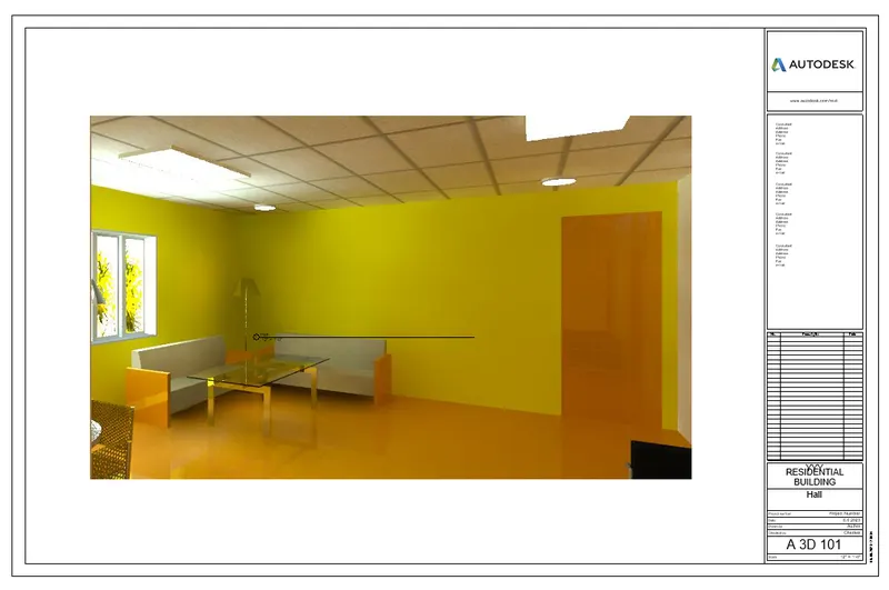
- Kitchen
- Room
- Balcony
Step 2: Rendering from out showing topographic features
Step 3: Rendering through structural framing
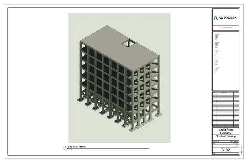
Result:
All the rendering 3d images of architecture, structure and topographic views have been sucessfully rendered and inserted in appropriate sheet template.
7) Print the set of drawing sheets created and submit the drawings from the architecture and structure model
Step 1:
- First we select the sheet we want print
- Click print option in ribbon tab or click ctrl+p
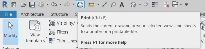
- The print dialog box has been appeared
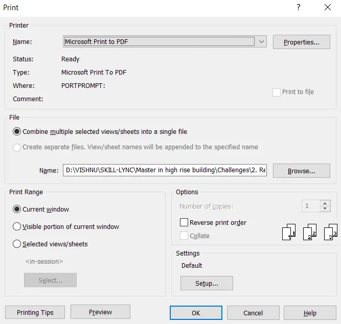
- In the name check box we choose what we want, that is directly to print or save to pdf option
- In the next option setup, it can be available change the paper type, orientation and some
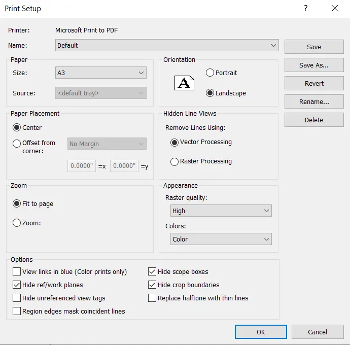
- In next option directly choose the sheet in print dialog box
- Print page > Selected view/sheets
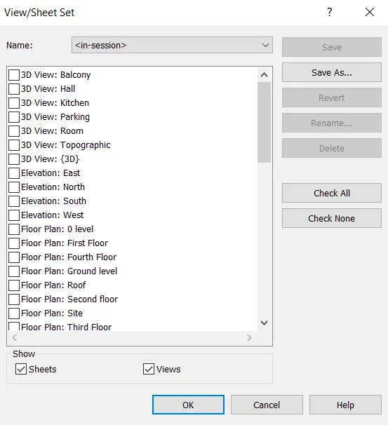
- After select the sheets or views click ok to create the pdf format
Result: