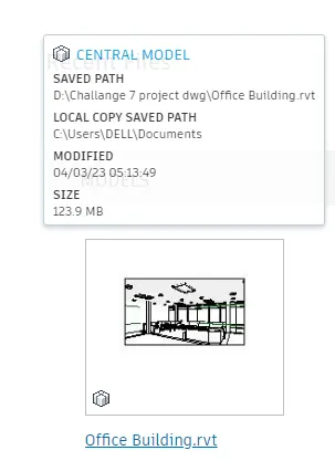
Creating Architectural and Structural model with 3D rendering using REVIT
1) Select the type of structure you want to build from one of the three below:
a. Multi-Unit Residential Apartment
b. Office Buildings
c. School
- I want to build Office Building from the given type of different structures.
2) Assume reasonable assumptions for geographic and location details for your project modeling. Based on assumptions and type of structure selected identify the modeling requirements from NBC
- ASSUMPTIONS FOR GEOGRAPHIC AND LOCATION DETAILS FOR MY PROJECT MODELLING WHICH I MADE ARE:
* I want to design the Office Building in plan/ Commercial area where a medium size population is located
* Road width infront of my appartment is 60'
- THE MODELLING REQUIREMENTS FOR MY APPARTMENT AS PER NBC ARE:
* Height limit as per FAR calculation as per NBC TABLE
* Fire and safety according to NBC TABLE
* Min width and length of rooms area according to NBC
3) Using the structural model, include the following components based on the type of structure selected
a. Foundation – Isolated / Wall/Matt Foundation
b. Columns
c. Beams Connected to Columns
d. Roof Framing/ Truss
e. Floor / Decks
f. Floor Openings for Elevators and Stairs
AIM: To draw the following srtuctural components in model
Tools and commands used:
- Columns
- collaborate
- Foundation
- Floor
- stairs
PROCEDURE:
STEP-1: Open Revit Software:
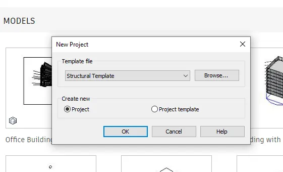
- Open the revit software 2023 and click on NEW option
- Select structural template in template dialoge box - press ok then open structural template
STEP-2: Save Structural Template:
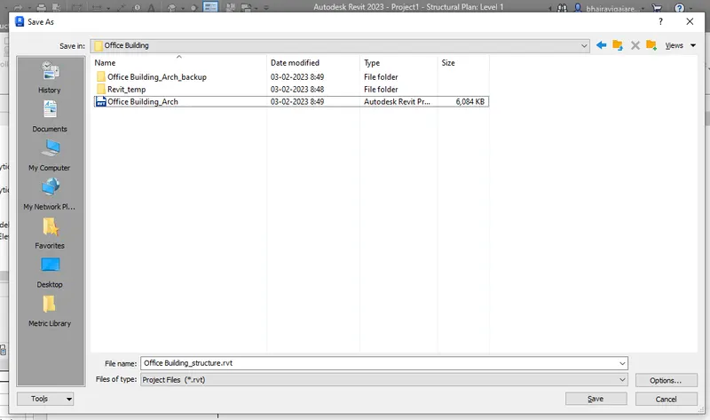
- Press Ctrl + s or go to File - save then save the project in appropriate location
- Save the project as Office building _Structure
- Click on save option
STEP-3: Draw grids:
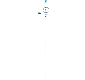
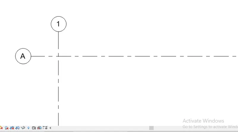
- Click on architectural tab and on grids, and draw the grids ,click from bottom to top for the vertical grid and name it as 1.
- For horizontal grids, draw from right to left and name as A.
STEP-4: Draw Levels:
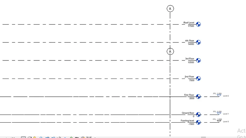
- After that Go to elevation - East in project browser Already there are two levels by defualt.
- Rename the level 0 as Footing level by double clicking the level 0 . Rename the level 1 as Ground floor -1500'.
-To create new level, in architecture tab - click on levels,clcik on pick line option and give the offset as 3500 and then click on it and rename the 1st floor.
- similarly create 2nd floor, 3rd floor, 4th floor roof level at 17500mm
STEP-5: To create project basepoint and shared coordinates:
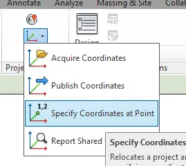
- Now go to manage tab and click coordinated from the project location tab and from drop down list click on specify coordinates at a point.
- Click on the intersectio of grid 1 and 2 , now a dialogue box apperas and put the value as 0, 0 for East /West and click ok. Now the grid one coordinates is set to 0. Again do similar processes to North/ South.
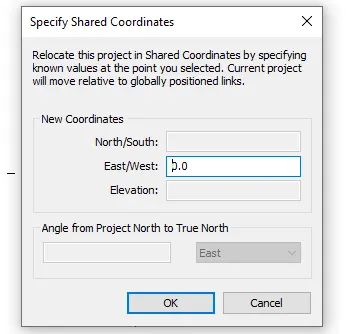
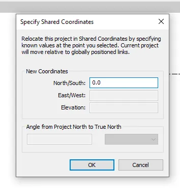
- Now the coordinates is set as 0,0 so that we can use this as the common coordinates when working in structural template.
- For the base point, type "VG"visibility / graphics dialouge box appears ,click on site and expand the options.
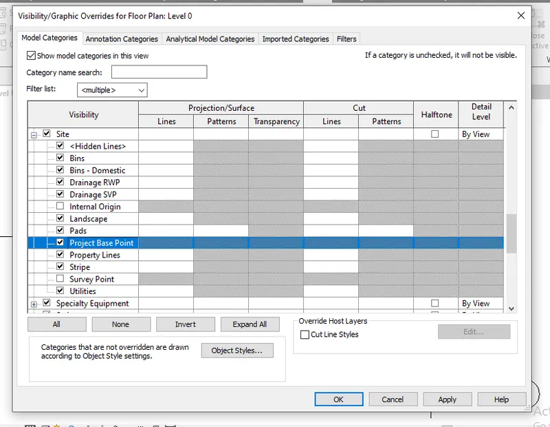
- Tick the project base point , click on apply ok so that it appears on the Rivet screen.
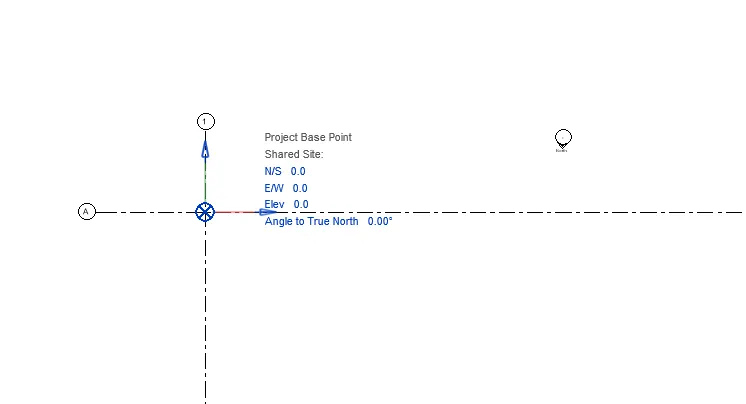
- If we double click on the base point , the coordinates of the particular point apperas.
- Drag and place the base point on the intersection of the grids and double click it. We can see that the coordinates are 0,0 for North/ south and East/ West
STEP-6: Synchronize with central:
- Go to collabortae tab , click on collaborate .

- Save the file and collaborate dialogue box appears.
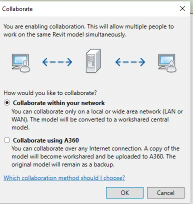
- Click on collaborate within your network and click ok.
- Click on save button, then dialouge box will appear.
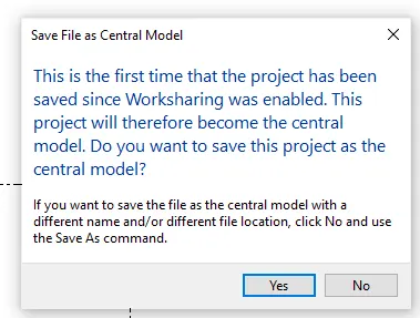
- Click yes to save this as the central model.Now the file is saved as central model file.
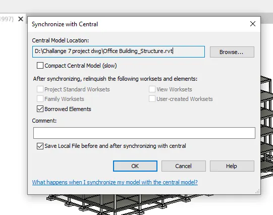
- Now click colloborate tab and select synchronize with central and click ok when a dialog box appears.
STEP-6: Create architectral model template:
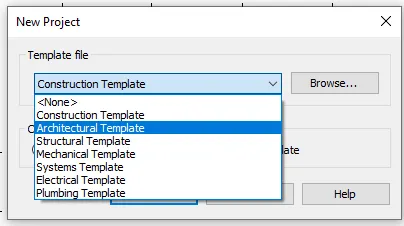
- Open the revit software 2023 and click on NEW option
- Select Architectural template in template dialoge box - press ok then open Architectural template
STEP-7: Draw grids and To create project basepoint and shared coordinates :
- Then draw the vertical and horizontal grid
- Repeat procedure for creating shared co-ordinates which we are doing in structural model
STEP-9: Save Architectural Template:
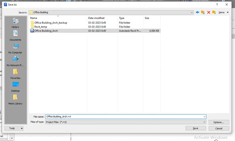
- Press Ctrl + s or go to File - save then save the project in appropriate location
- Save the project as Office building _Arch
- Click on save option.
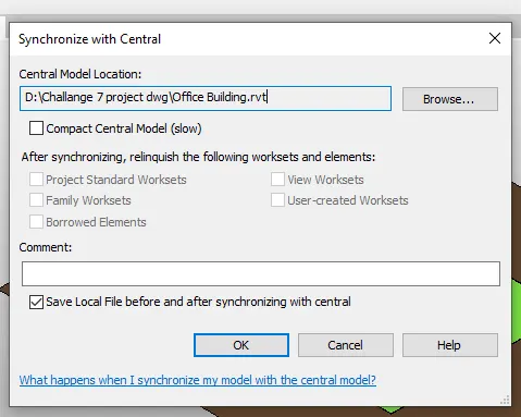
STEP-10: Synchronize with central:
- Again Go to collabortae tab , click on collaborate .
- Save the file and collaborate dialogue box appears.
- Click on collaborate within your network and click ok.
- Click on save button, then dialouge box will appear.
- Click yes to save this as the central model.Now the file is saved as central model file.
- Now click colloborate tab and select synchronize with central and click ok when a dialog box appears.
STEP-11: Link architectural and structural model:
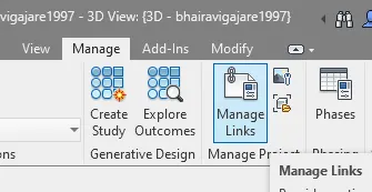
- Click on Manage tab then select manage links
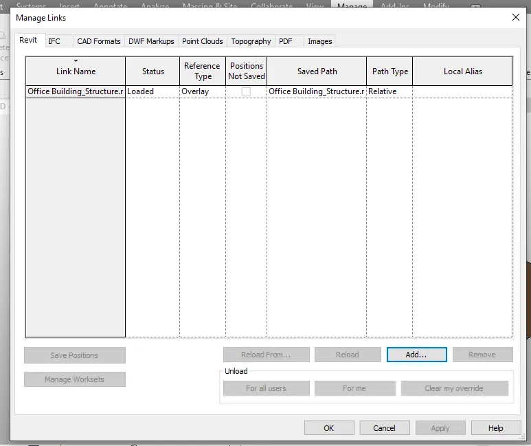
- After opening of manage link dialogue box select Revit section click on add select office building structural file okay and then press again okay
STEP-13: Copy Monitor:
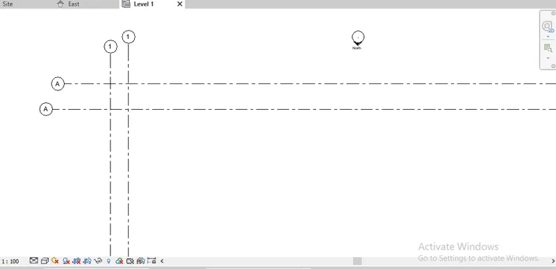
- Now the structural grids will appear on architectural model.
- Go to collabrotae tab, click on copy/ monitor
- From drop down list , click on select link.
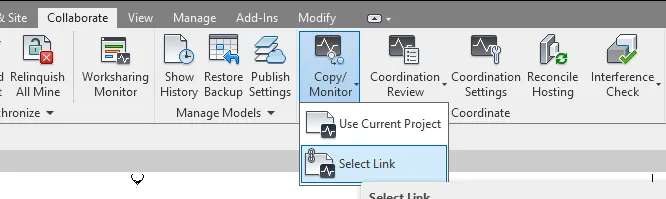
- Then select the Structural link loaded into the architectural model.
- Click on copy , tick multiple option
- Select all the grids from the structural model
- Click on finish and tick the finish button on the top.
- To check if it is copied type VG command , go to rivet link tab.
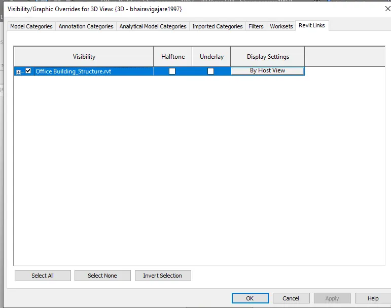
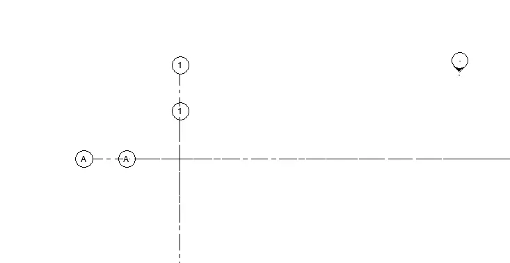
- Click apply and OK, we can see that the architetcural grid is visible as it is copied tothe structural model.
STEP-13: Draw Remaining Grids:
- Draw vertical grids at a distance 5200,6200,5200,4100,5200 and 3900
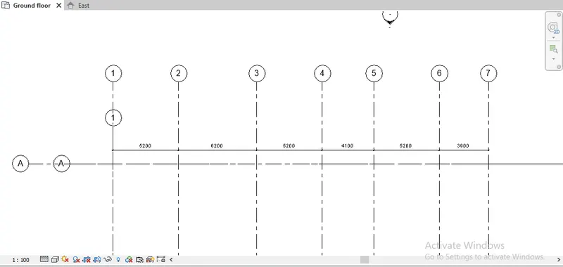
- Again draw the required horizontal grid at a distance 6100, 6000, 6100, 6200, 6000, 6150, 6000, and 6500.
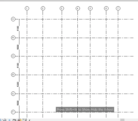
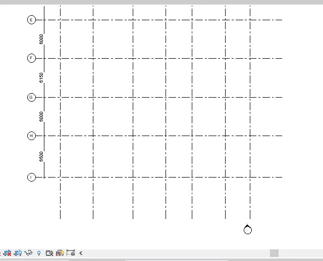
- For the add vertical and horizontal grids for saticase coloum.
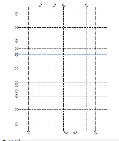
- Then make it synchronize with central after that using copy/monitor option and copied these grides in architectural model.
- Save it And close the Architectrual file
STEP-13: Draw structural component:
- After completion off synchronise with central process create structural frame by draw the following structural component.
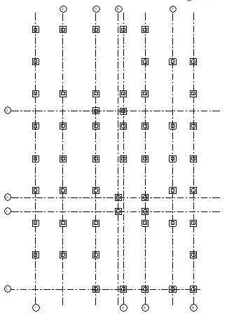
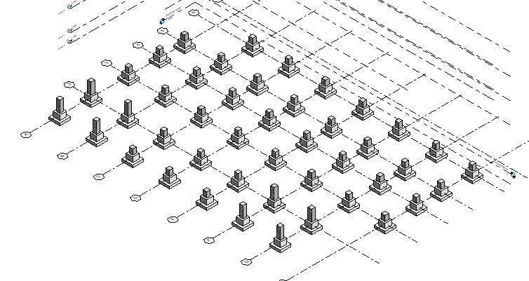
a. Foundation – Isolated / Wall/Matt Foundation
- Go to the Foundation level in Floor plan from project browser then select structural tab
- Click on ISOLATED FOOTING
- After that go to the load family
- Select M_ Sleeve Foundation
- Click on open
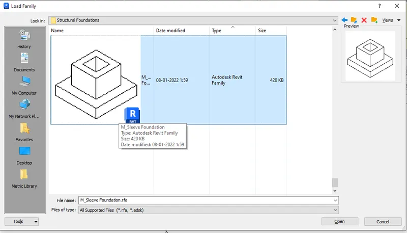
- Then click on ON GRID option.
- Select the grids and click on finished.
b. Columns:
- Then same way go for column go to the structural tab
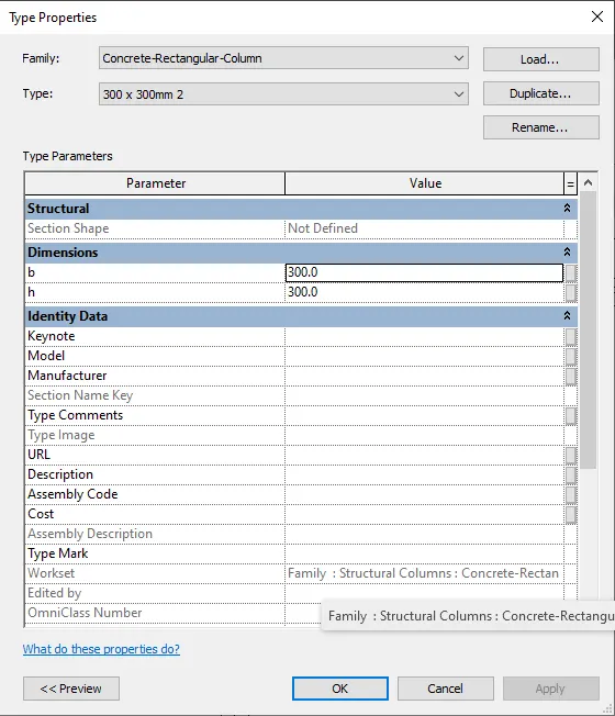
- Select the structural column. Click on concrete rectangular column from property browser
- After that select edit type add make a column size according to requirement i.e.column size 300x300 Press ok
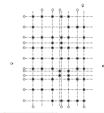
- Click on grid option and mark a column
- Select the base level as foundation level and top level as roof level and some coloumn top level upto roof level and click on apply
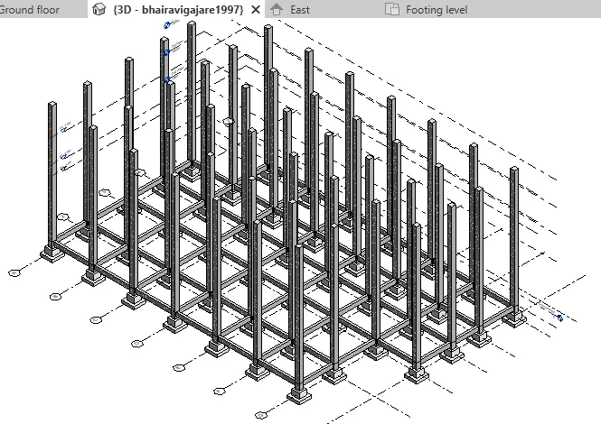
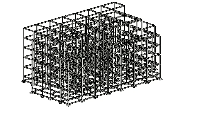
c. Beams Connected to Columns:
- Similarly draw the beams having size is also 300 x 300mm
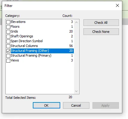
- Select all then click on fliter check the only structural framing (other) box. Click ok
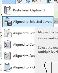
- Click on copy From modify tab in clipboard section then best click on past select align to select level - -

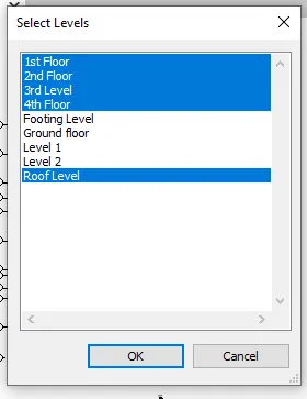
- select required levels and press okay
d. Roof Framing/ Truss:
- In my project there is no roof framing or truss
e. Floor / Decks:
- Click on ground floor and Again goes into structural tap select floor option then property browser select appropriate or required floor i.e Floor Generic 300mm 2
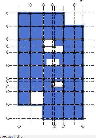
- Then click on pick a line in draw section from modify tab and draw floor then click okay
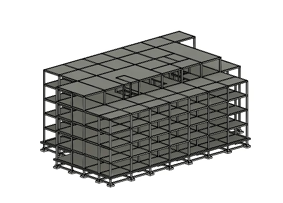
- After that select floor copy it and and for paste select align to select level
f. Floor Openings for Elevators and Stairs:
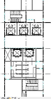
- Click on shaft in opening section from structural tab
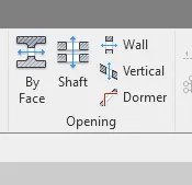
- Draw shaft for elevators and stairs and by using rectangle to create floor opening at required place.
- Select the base level as Ground floor and top level as 4th floor and click on apply
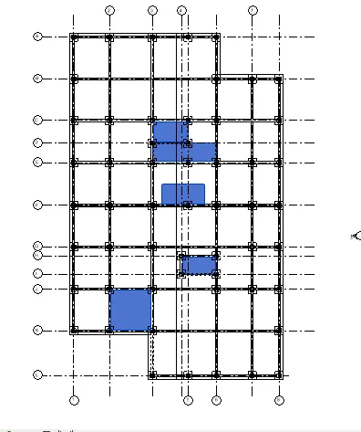
Result: All the structural components like beams footing,slab are palced successfully in the model
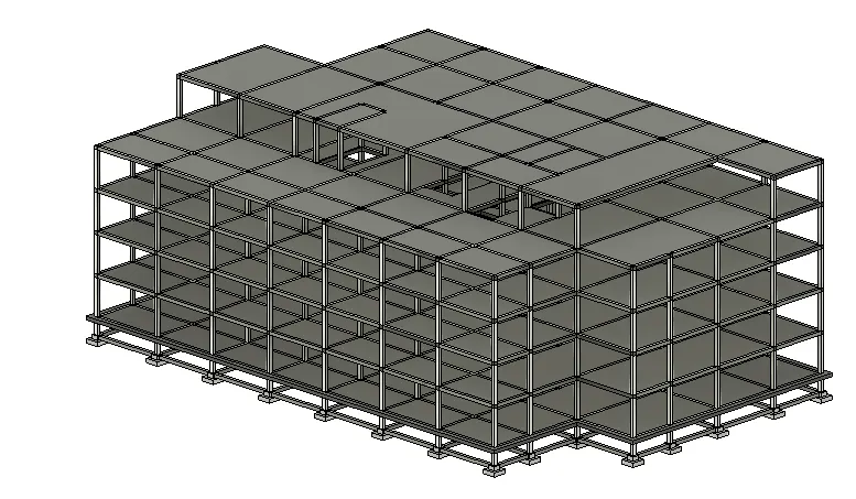
* Then save it and make a synchronize with central. close the structural file.
4) Using the architectural model, include the following components based on the type of structure selected
a. Wall Layout with appropriate material and finishing
b. Exterior façade with fancy finish
c. Interior partition walls to size rooms
d. Components to add details to a room ( Desk, Chair, Lighting, Plumbing fixtures)
e. Add components such as stairs Elevators
f. Have at-least one side of the building with curtain walls and glass panels
g. Include interior and exterior lighting fixtures
h. Place proper topographic components from outside ( Trees, Parking, Plants) to add details to the model
AIM: To draw the architectural model for office building
Tools and commands used:
- Doors
- Architectural tab
- Rooms tags
- Stairs
- Ligthing
PROCEDURE:
STEP-1: To update architectural model
- After creating structural model reload in architectural model in manage link dilogue box.
Go to collabrotae tab, click on copy/ monitor
- From drop down list , click on select link.
- Then select the Structural link loaded into the architectural model.
- Click on copy , tick multiple option
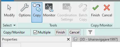
- Select all the Coloumn, beams, footings and shaft from the structural model or selsct whole model and using filter option for select required components
- Click on finish and tick the finish button on the top.
- To check if it is copied type VG command , go to rivet link tab. and uncheck the box. -apply- ok
STEP-2: Draw architectural component:
1) Walls:
a. Wall Layout with appropriate material and finishing:
- Go on Project browser click on ground floor
- From archietctural Tab select wall then select wall type from Properties browser
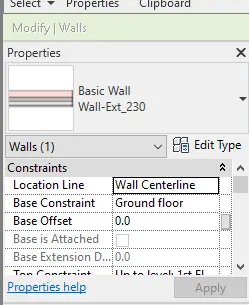
- Click on edit to create duplicate give name "External wall 230mm" then make a required changes for geting thickness 230mm and provide appropriate material.
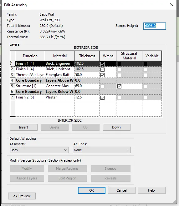
- Draw the wall which is external wall
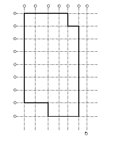
Ground Floor
b.Interior partition walls to size rooms:
- Go to the architectural tab select wall choose the basic wall from properties browser.
- Edit it by click on edit type and rename it as a internal wall. Also make the changes in the its structure by clicking on edit in structure section for getting 120mm tickness and apply material. click ok
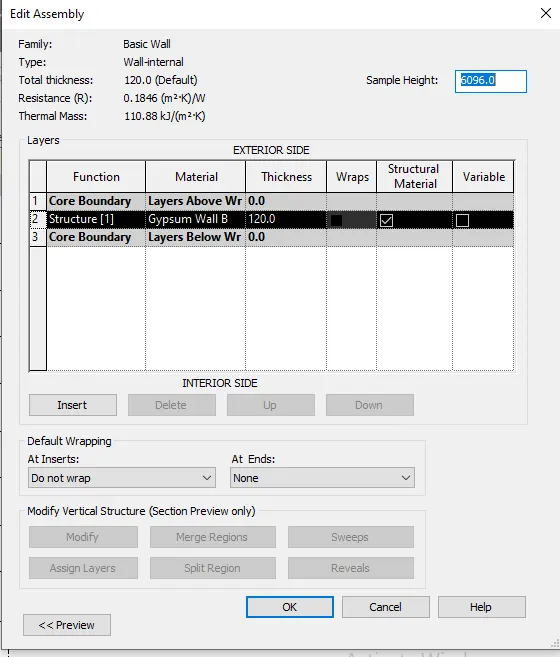
- Now draw the office rooms with conventient size By choosing interior partition wall
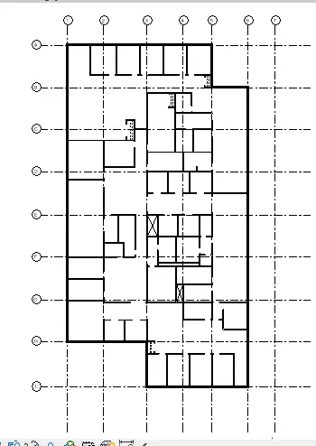
Ground Floor
- Click on 1st floor in floor plan and Similarly draw 1st floor.
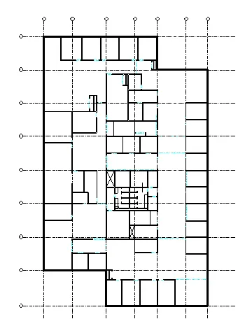
-Select whole plan click on copy and paste it at 2nd floor and 3rd floor by selecting align to select level
-Again repeat this procedure for making 4th floor draw outer wall by selecting external 230mm wall then create office rooms and other spaces by using basic inter wall.
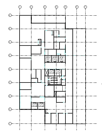
4th Floor
2) Provide room tag:
- Go to architetctural tab select the room seperator.
- Draw it where required
- Again click on room tag place a room tag to each room.
- Repeat this procedure again for each floor
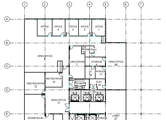
Ground floor A-E
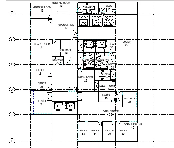
Ground floor D-I
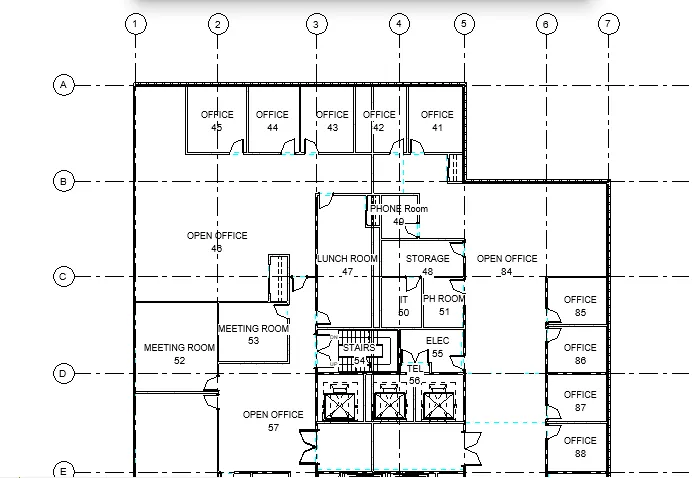
First floor A-D
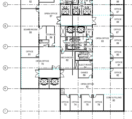
First floor D-I
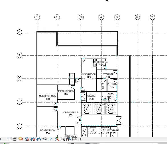
4t floor A-E
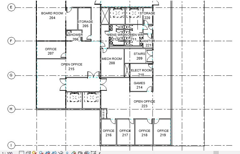
4th floor E-I
3) Floors and roof:
- Go to the ground floor Click on floor in Architectural tab
- Select floor type
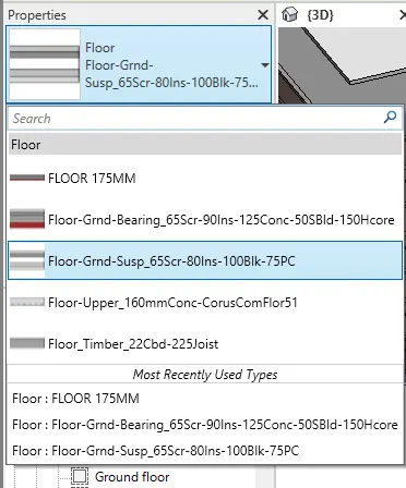
- take a pick line in draw section. Draw the floor Click ok
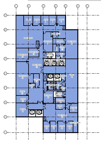
- Repeat procedure for 1st floor 2nd floor and 3rd procedure
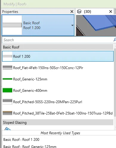
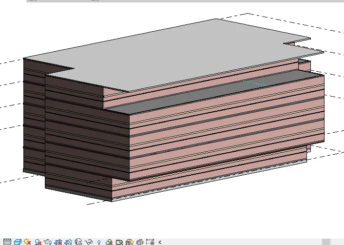
- Again for draw the roof select Basic Roof 200mm and then sketch it at roof level.
c. Add components such as stairs and Elevators:
1) Elevators:
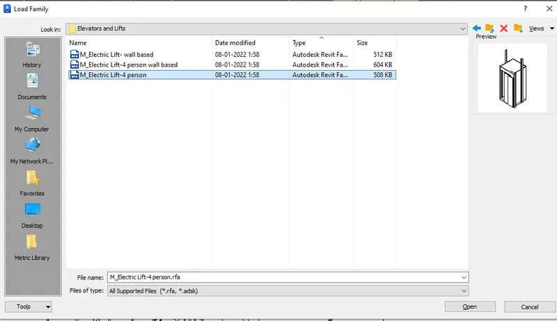
- Go in load family select required Elevator in Elevator and lift from apecial equipment. Click on open
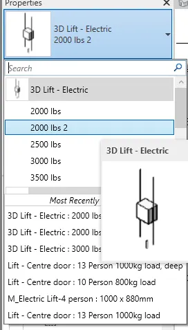
- Select its size from property browser as 2000lbs
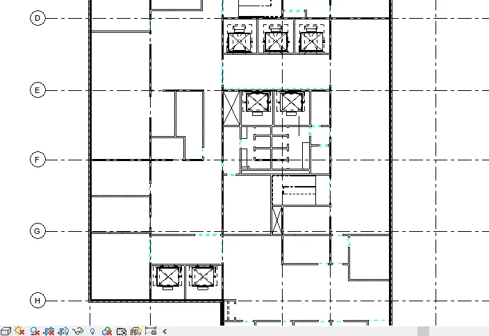
- Place the elevator in elevator shaft opening.
2) stairs:
- Go to the archicture tab
- Click on stair option
- Select the Straight staircase And draw it in u shape having width is 1000,1000 and 1000 in staircase shaft opening.
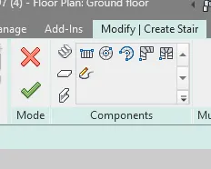
- Give the base constent as foundation level and top constant as 1st floor
- Provide a 20 steps number in properties browser Click ok
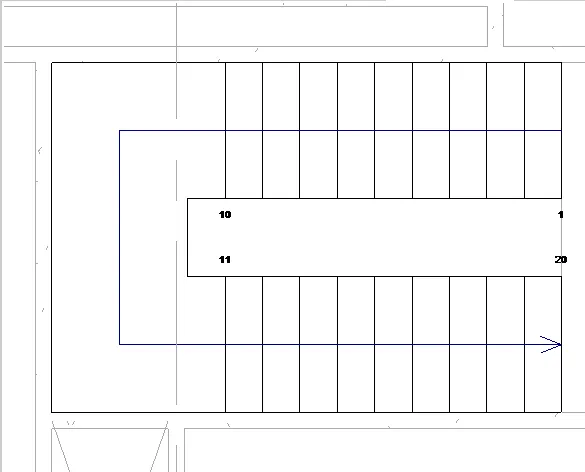
- Copy this staircase at 1st floor, 2nd floor, 3rd floor
d.Exterior façade with fancy finish /Have at-least one side of the building with curtain walls and glass panels:
1) curtain walls and glass panels:
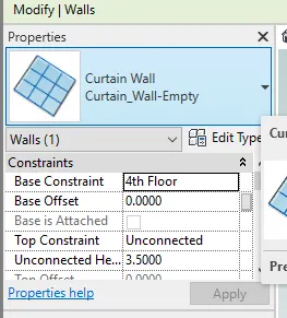
- After completion of all wall layout select outer walls and change their type
- Select them and change their type as a curtain wall empty
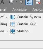
- Go on architectural tab select curtain grids then click on all segment
- Place grids vertically 0.5,0.3,1.9,0.3 and 0.5m from top and horizontaly divide the whole length for geting appropriate length of grid here 1.2m is provide ( For dividing length place 1st grid at center we get 2 parts the provide agin grids at center of both side i.e. left and right we get 4 parts. Repeat this procedure until you get desire parts)
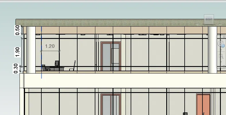
- Similarly place other faces the vertical distance is same only horizontal size is change according to length
- place cursor on horizontal line
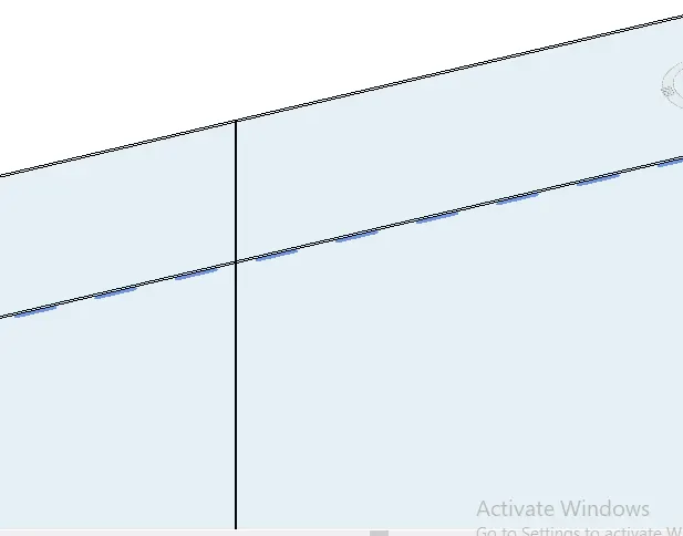
- press the tab 2/3 times until you have do not get required part selected you get following result.
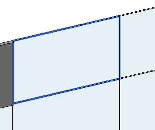
- select solid form in system panel from property broser
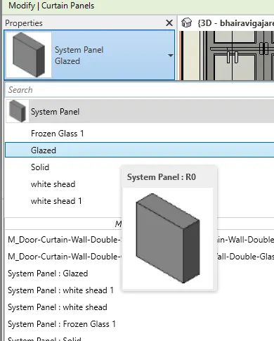
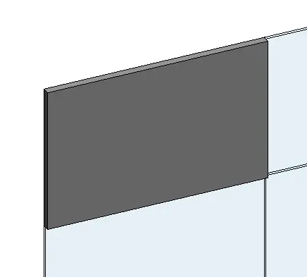
- Rpeat this procedure for each side and top and bottom to each floor I.e. for all 0.5m panels make a solid glazed
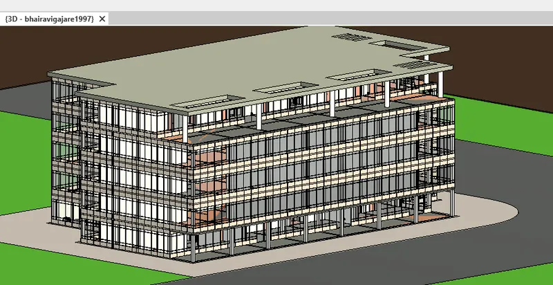
2) Exterior façade with fancy finish by using model
- From architectural tab click on component select model in place
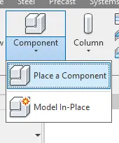
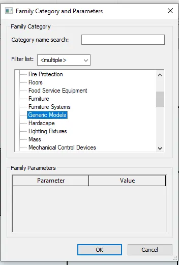
- select Generic model click okey
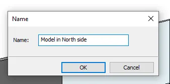
- Give model name press ok
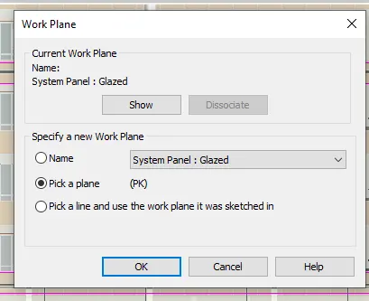
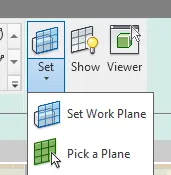
- select extrusion and set a work plane as a pick a plane-ok then click on show
- select rectangle. place a cursor at desired point click on it and draw required shape. i create mirror c shape having width is 0.1m and length is 0.1m more than the whole length of that side. i.e(L + 0.1)
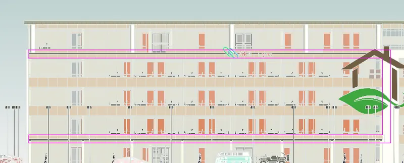
- Click on finish
- Again repeat this procedure and create models for other side.
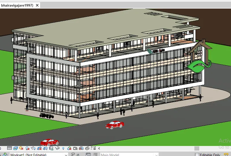
South-East
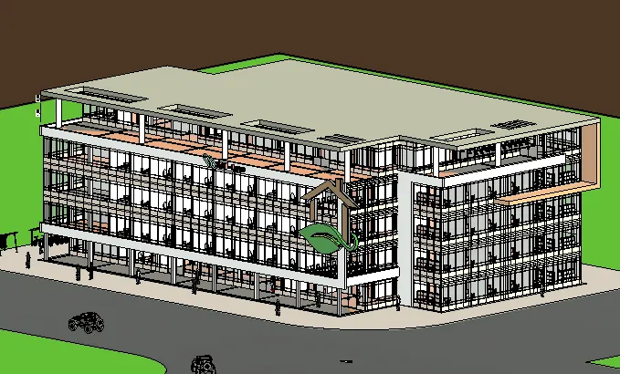
North - East
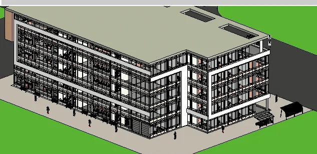
West - South
3) Create Logoes:
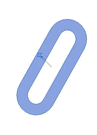
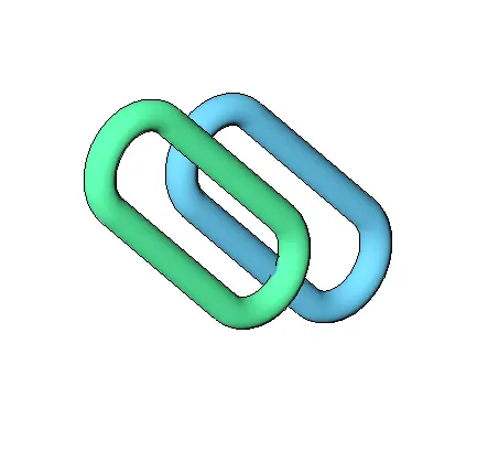
i) Skill lync:
- Go to the file- new- family- select Generic moadel- Open
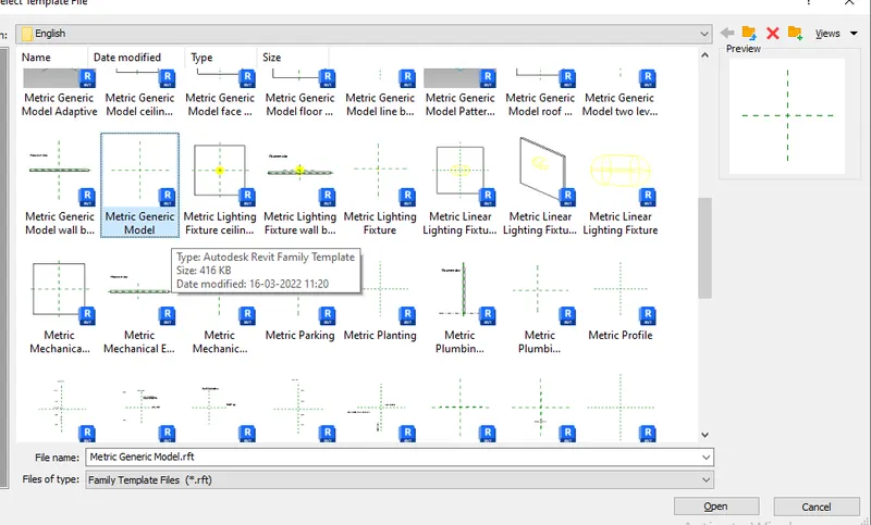
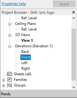
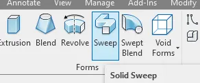
- Select front elevation from project browser. click on sweep in create tab
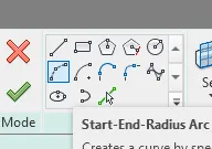
- Draw the logo by using line and start - end - radius arc
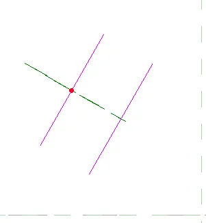
-
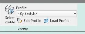
- Select this object then click on select profile
- Select edit profile Then click on 3D view- open view
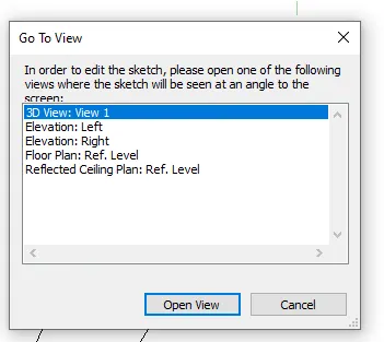
- draw the circle around the pink point
- Click on right click
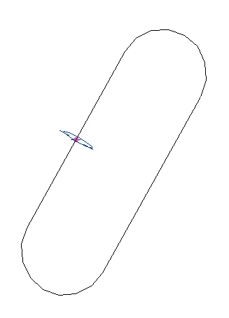
- Again Click on right click
- Copy this object and place required place
- Provide appropriate material
ii) Home:
- Go to the file- new- family- select Generic moadel
- Select front elevation in project browser
- Click Extrusion in Create tab. Draw House shape by using line click finish
-Again Click Extrusion sketch inner rectangles
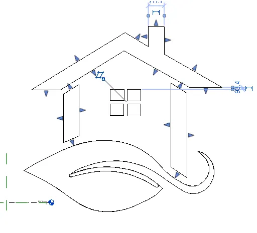
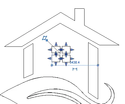
- Select Extrusion then select spline And draw outer and inner curve for making leaf
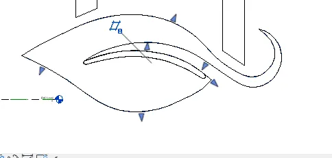
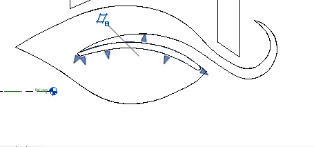
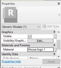
- Then apply material from property browser for each part.
4) Place logos and Model text
- Select front wall then click on section box in modify tab from view section
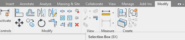
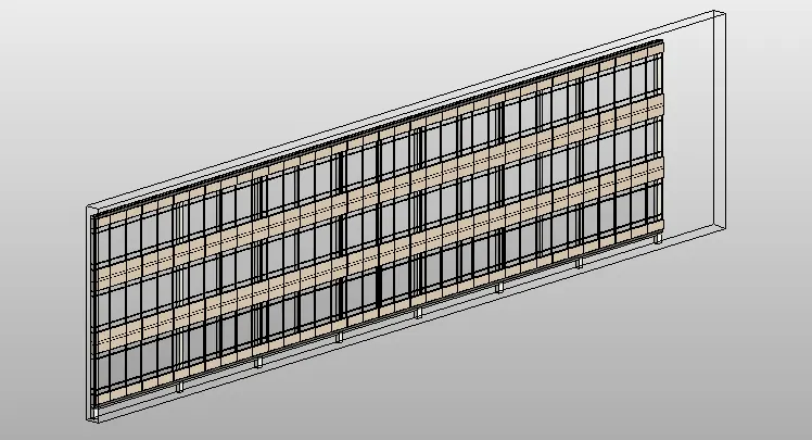
- Load both logo one by one to click on load into project
- Place the both logo at required place
- Set a plane as requirment
- For placing model text Go in architectural tab click on model text
- Give the name "Skill-lync" press ok
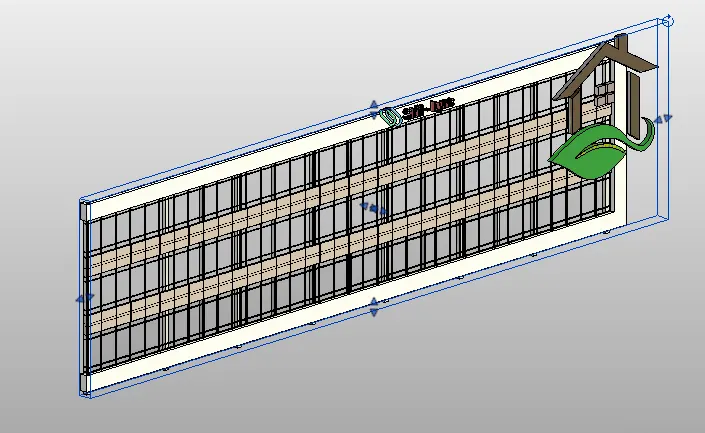
e.Components to add details to a room ( Desk, Chair, Lighting, Plumbing fixtures):
1) Plumbing fixtures:
- Click on Component in architectural tab - Place a component
- Select the US - Plumbing - Architecture - Fixture - Urinal/ Water closet - open
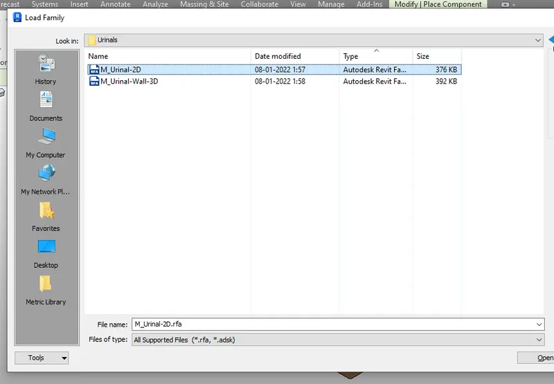
- Then place them in womens and mens WR
- Again load sink componenet similar way and palce them
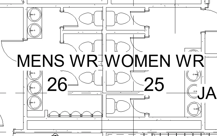
- Select these fixture and paste them 1st floor to 4th floor using align to select levels
2) Desk, Chair, Doors:
a) Doors:
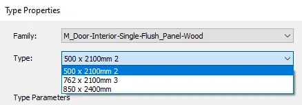
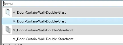
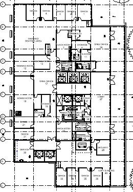
- Again loads different types of doors these are following with dimensions
- These doors provide to Staircase room, enetrance near to lift , stervice room etc
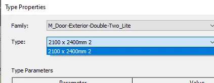
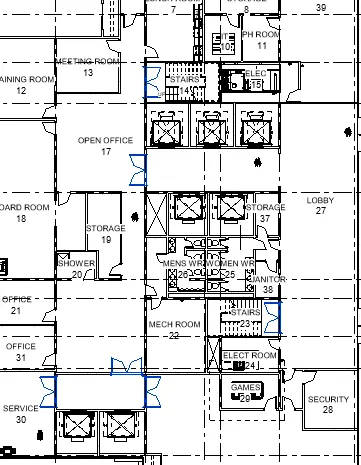
- These doors provide for office room, meeting room, training room washe rooms etc according to their size requirement
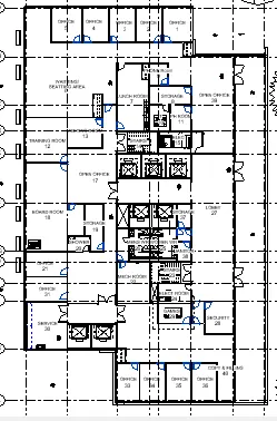
- This door is provide as a outer door of service room
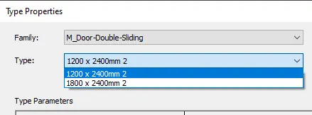
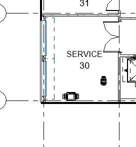
- These above 3 types of doors copy and paste on 1st to 4th floor.
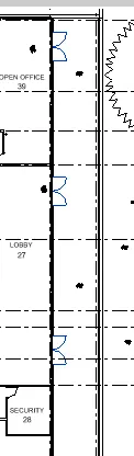
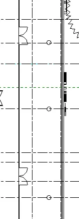
- This type of door used for entrance at Ground floor and And 4th floor to curtain wall.
- Delete the curtain grids in that portions for door placing and then place the doors
Ground Floor 4th floor
Ground floor
1st floor
4th floor
b) Desk, Chair,:
- Similarly load desk with laptop, chairs, dinning table with chair, kitchen model, bench for seating in outer area and meeting table with chair.
- Place these are at required position.
- again This furniture copy and paste at differnt level
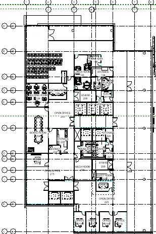
Ground floor
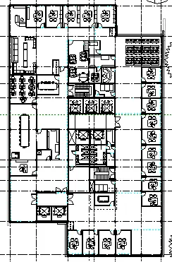
1st floor
4th floor
h. Place proper topographic components from outside ( Trees, Parking, Plants) to add details to the model:
1) Topography:
- Goes on site tab
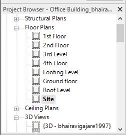
- Click on massing and site tab select topography
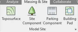
- Select place points and place the points arround a building at particular distance
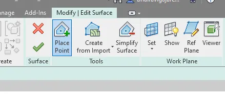
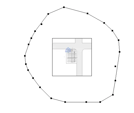
- Then select the model line in architectural tab for giving the shape of surface
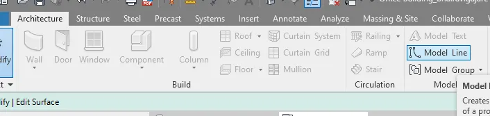
- Draw rectangular shape
- select point drag it and place the points at its corner
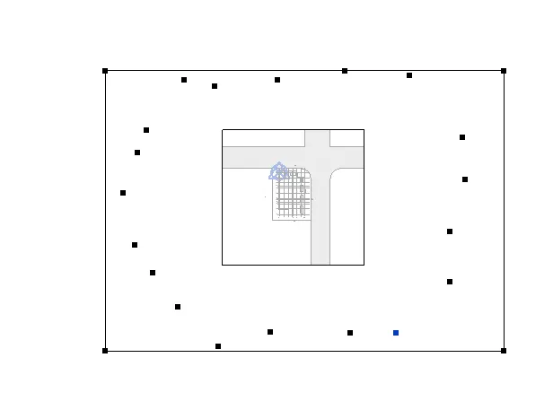
- Delete other point click on right click
- And provide material from property browser as a soil
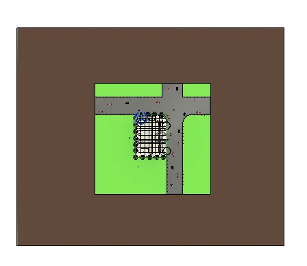
2) Building pad:
- Click on massing and site tab select Building pad
- select all outer sides of floor and click ok
3) Outer area of office and road:
- Architectural Tab - select floor
- Draw floor line by using pick a line and one corner make a curved then click ok.
- Provide material to it as a concrete which is moving area
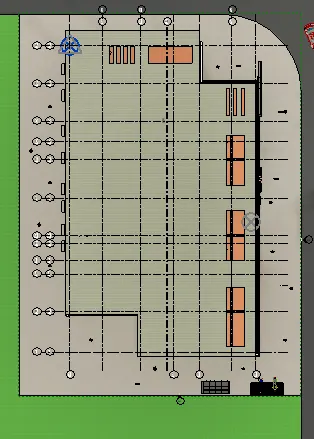
- Again draw floor by using a line for road and provide shape of road
- provide the materia as a bitumen for road
- similary for garden draw floor and provide material as a grass
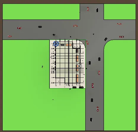
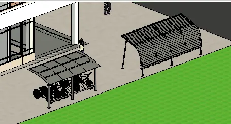
4) Parking:
- Go in load family and load the parking (Which i have downlaod it from browser) and place it at south corner of office
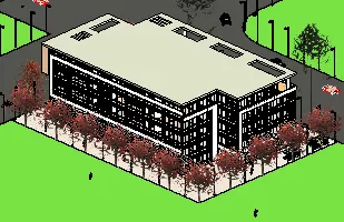
5) Trees, Plants :
- Select site component from massing & site
- Then select required type of tree
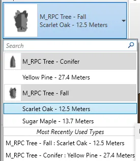
- Place it at 3side of building
g. Include interior and exterior lighting fixtures:
- Draw the ceiling by using ceiling option. select grid ceiling
1) Interior light fixture:
- Go to the load family and load following lights.
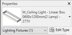
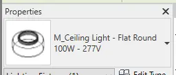
- open the ceiling plan of ground floor and place the light fixture
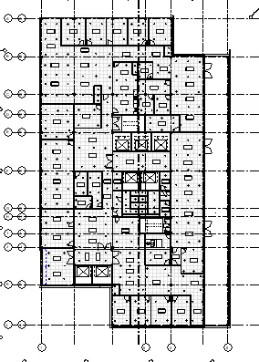
Ground floor
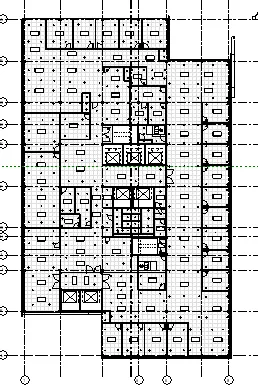
1st floor
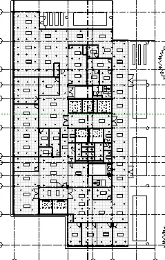
4th floor
2) Exterior light fixture:
- Similarly load the exterior light fixture
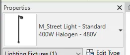
- Place this light fixture both side of road and arround of building
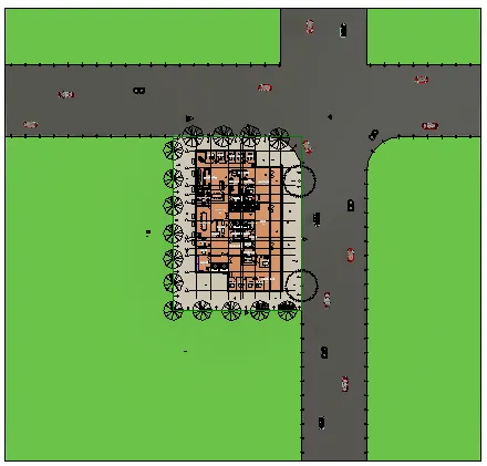
i. Other changes provide in bulding:
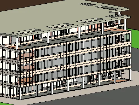
1) Architectural coloumn:
- Go to the architectural tab select coloumn select 300 x 300 mm square coloumn at ground floor and 600mm diameter at 4th floor.
- Give the material as a white colour
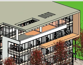
2) Create a fancy roof:
- Select a roof then click edit profile and select rectangle and a create a design as per requirement
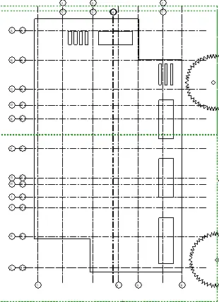
Result: All the Architectural components like diifferent types of wall, stairs and elevator, lighting fixture, deatil room componenet, Topography component etc. are palced successfully in the model
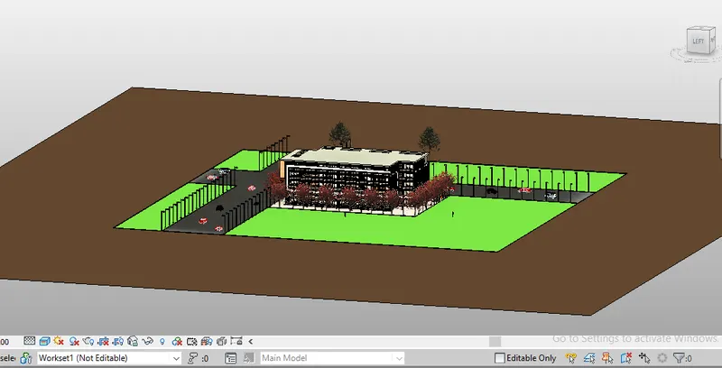
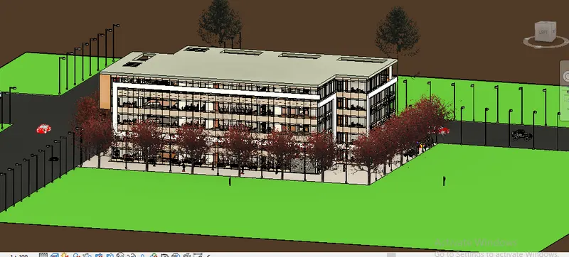
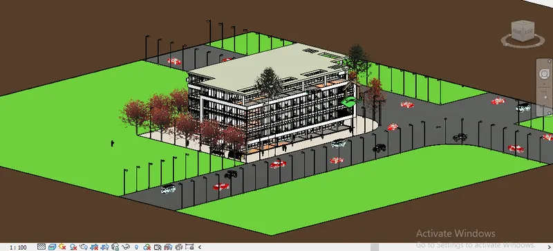
5) Provide a set of drawings in an architectural and structural model to list the following details with categories and appropriate sheet templates included
a. Floor Plans with Annotations:
b. Elevations:
c. Sections:
AIM:To provide set of drawings in architectural and structural model to list few details with categories and appropriate sheet
Tools and commands used:
- Sheet
- view
- elevation
- floor plan
- section
PROCEDURE:
1) Creating scope box:
- After completion of creationg both architectural model and structural model
- My plan size is too large which is not set properly on sheet so hence i am applying scope box.
- For applying scope box - Go to in view tab select scope box
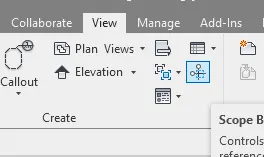
- Draw the rectangle upto required area.
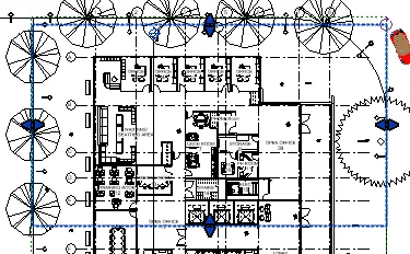
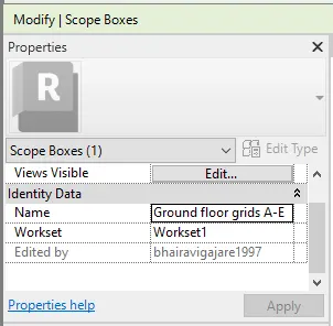
- Give to name it as a "Ground floor grids A-E" in properties browser then click apply
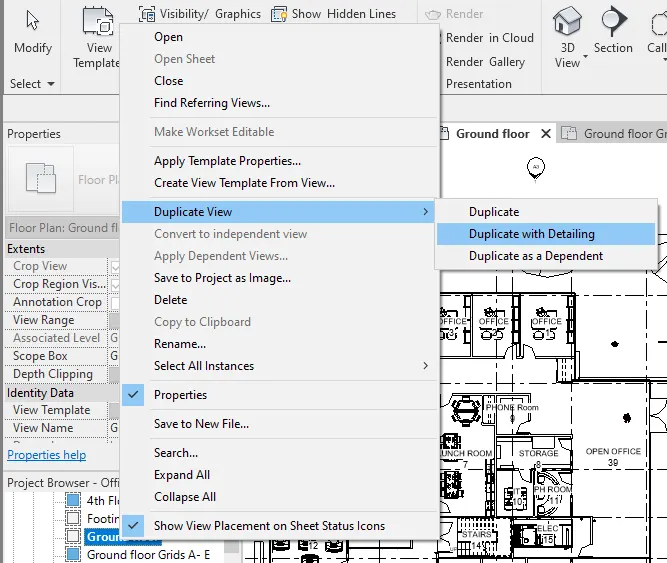
- After that go to project browser - right click on ground floor - select duplicate view- click on duplicate with detailing
- Rename this duplicate view as a "Ground floor grids A-E"
- Go in a properties browser - crop view and crop region visible check box- scope box : Select ground floor grids A-E
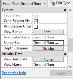
- Click apply
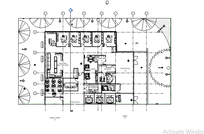
- Repeat this procedure for remaining scope box
- Craete following scope box.
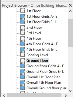
2) Project information:
- In manage tab go to project information , and add the informations.

- The project information dialogue box appears ,enter the organisation name, project details etc
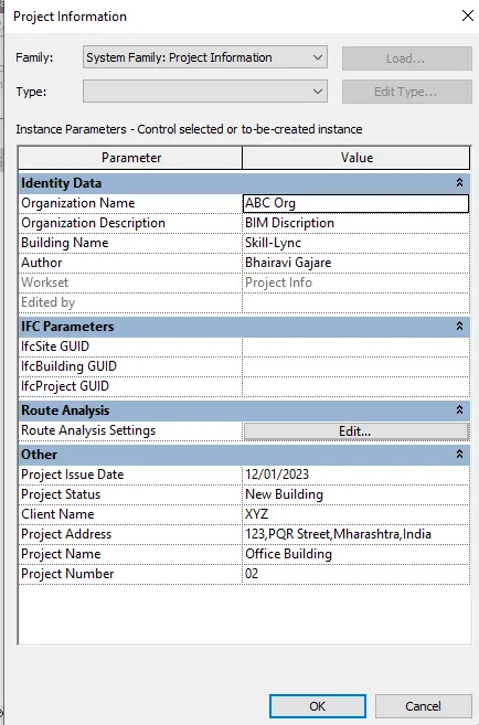
- Click ok
3) Creating sheets:
- Click on create sheet from the view tab .
- Select the sheet , or load another sheets ( if needed.) from load go to title box select template which you want. then click open
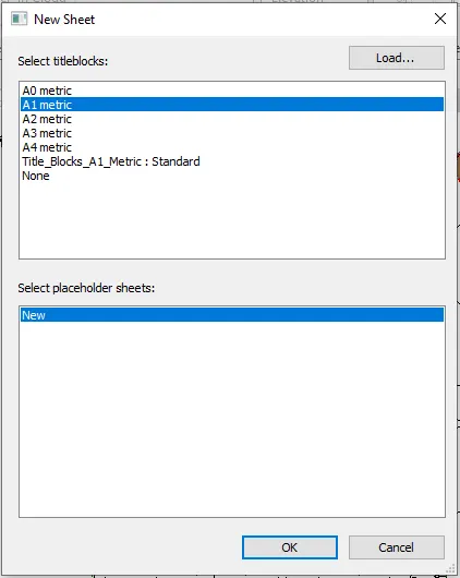
- Select A1 Matric sheet then click ok
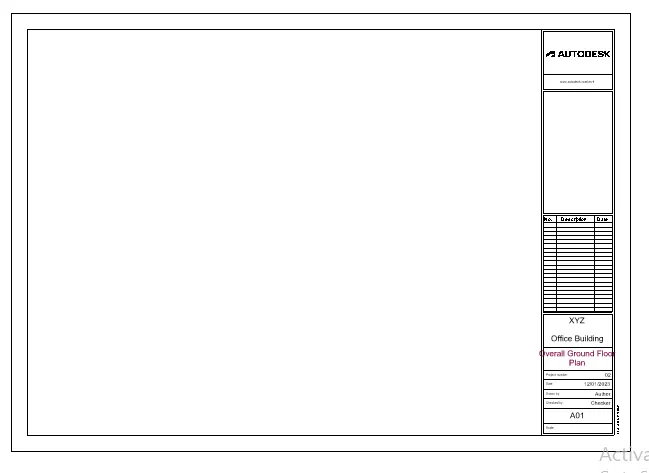
- for overall floor plans , sections and elevations
a. Floor Plans with Annotations:
i) Archietcture:
1) For Ground floor plan:
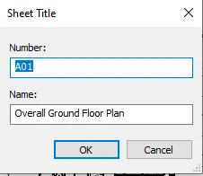
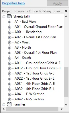
- The sheet created will be visible in the project browser , rename either sheet name as A01- Overall Ground floor plan
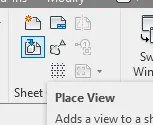
- Click on place view in the view tab , a dilaogue box appears.
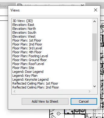
- If the duplicate view are not seen in list then go to the project browser select the floor plan -"Overall ground floor plan" drag it on sheet
- Set the view in proper position.
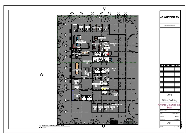
Overall Ground floor plan(Scale-1:120)
- Now select the A1 shhet .The sheet created will be visible in the project browser , rename either sheet name as A011- Ground floor grid A-E
- Place the view
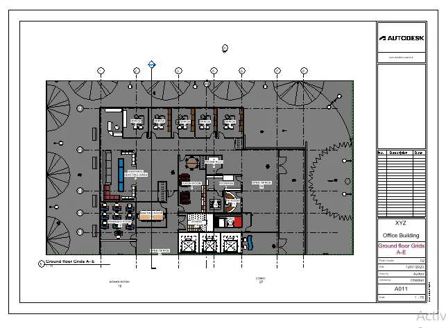
Ground floor grids A-E (Scale-1:75)
- Again create sheet for "Ground floor grids E-I" in same manner.
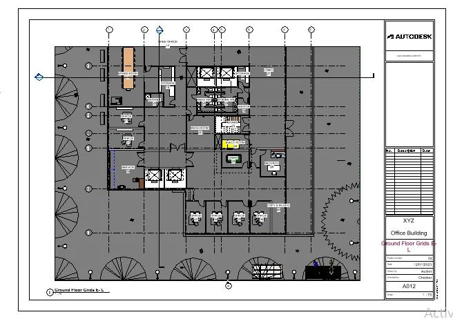
Ground floor grids E-L (Scale-1:75)
- Repeat this procedure for 1st floor and 4th floor.
2) For 1st floor plan:
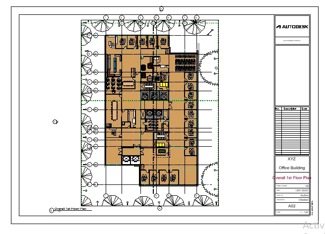
Overall 1st floor plan(Scale-1:120)
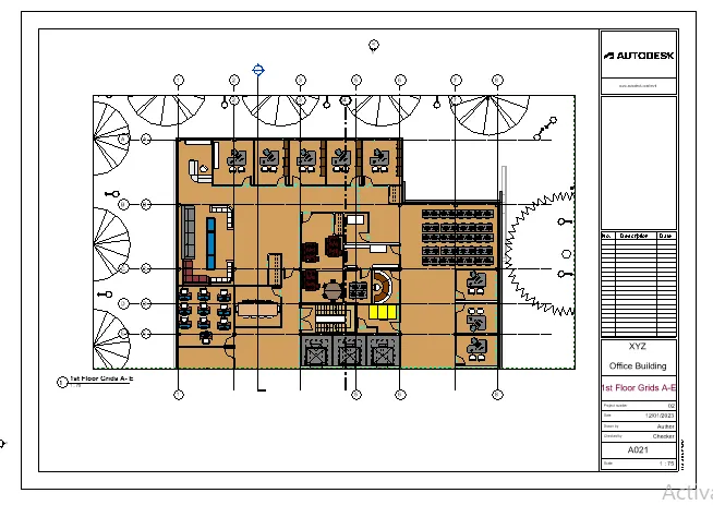
1st floor grids A-E (Scale-1:75)
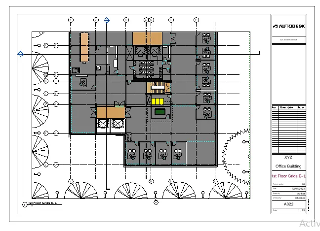
1st floor grids E-L (Scale-1:75)
3) For 4th floor plan:
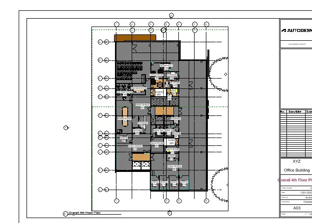
Overall 4th floor plan (Scale-1:120)
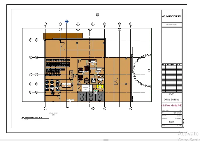
4th floor grids A-E (Scale-1:75)
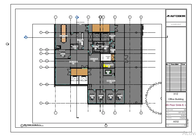
4th floor grids E-L (Scale-1:75)
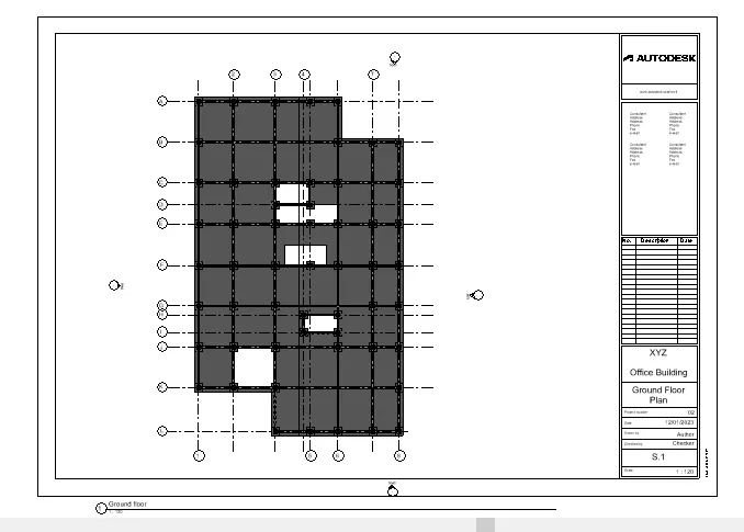
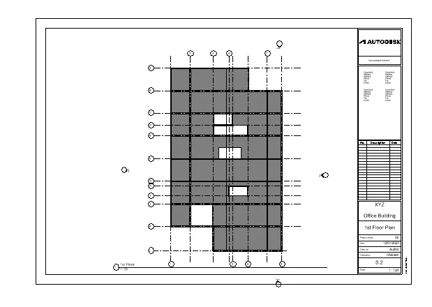
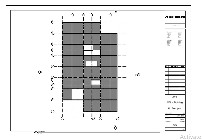
ii) Structure: (Scale-1:100)
1) For Ground floor plan:
2) For 1st floor plan:
3) For 4th floor plan:
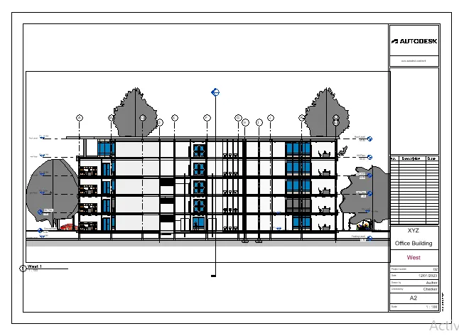
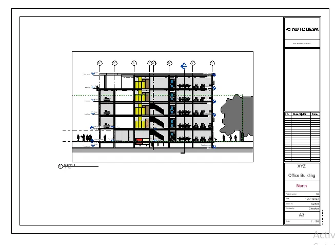
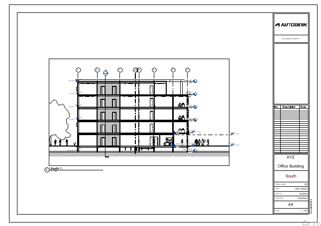
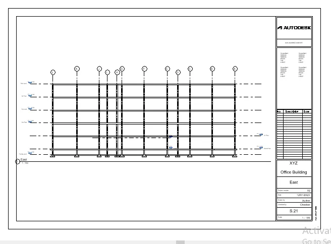
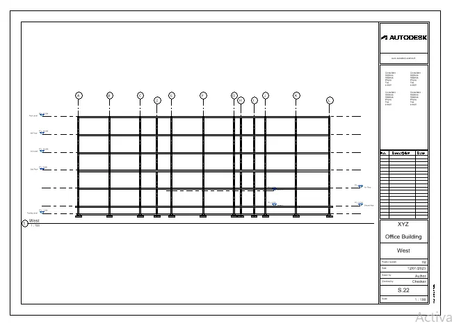
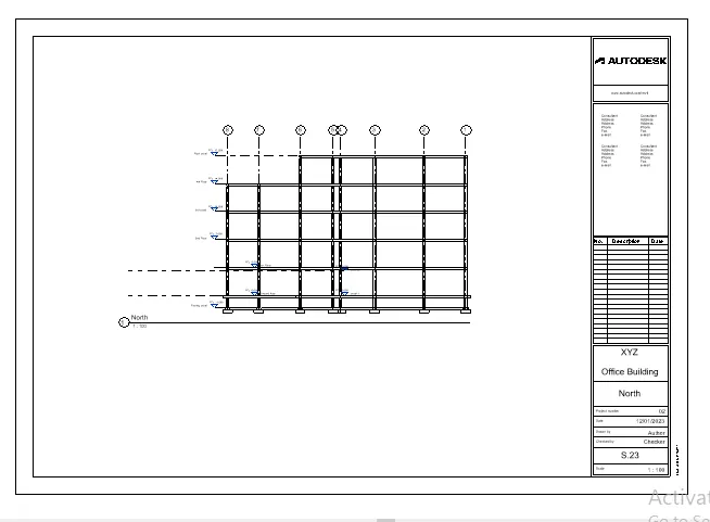
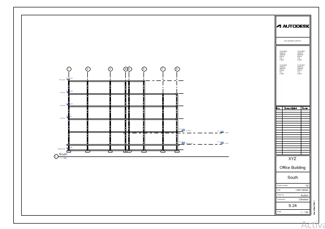
b. Elevations: (Scale-1:100)
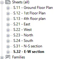
- Similarly create elevation sheet set
i) Archietcture:
1) East:
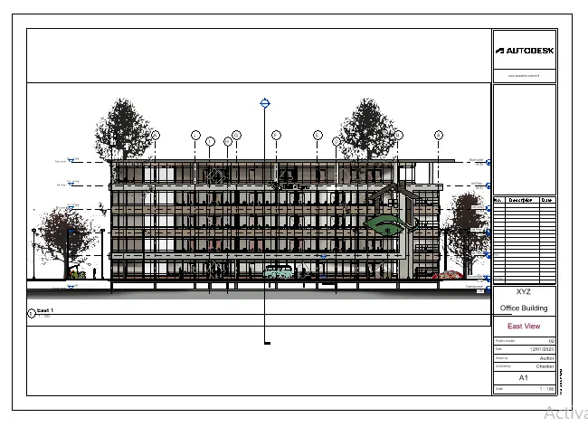
2) West:
3) North:
4) South:
ii) Structure:
1) East:
2) West:
3) North:
4) South:
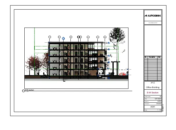
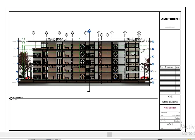
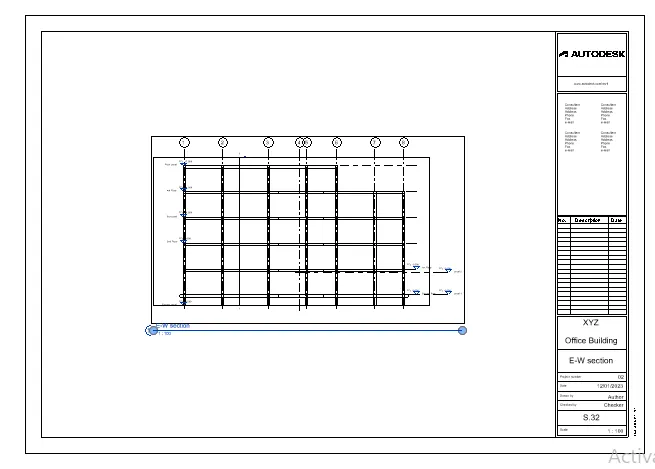
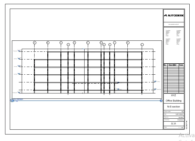
c. Sections: (Scale-1:100)
i) Archietcture:
1) E-W section:
2) N-S section:
ii) Structure:
1) E-W section:
2) N-S section:
Result: Respective sheets are created using sheet template in architecture model and structural model.
6) Using the Rendering settings, Render images of the 3D model produced and include the rendered images to the drawing sheets
a. Rendering from interior rooms
b. Rendering from out showing topographic features
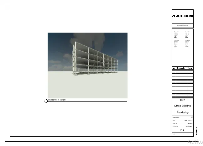
c. Rendering through structural framing
AIM:To tender the iamges which were capture by the camera view for example like the interior rooms topographic views and structural framing
Tools and commands used:
- Render
- Region
- Style
- Scheme
- Sheet
PROCEDURE:
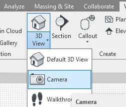
- Go to ground floor plan , from the view option-3d view- click on camera , and place the camera in which room we need the view.
- Again go on the view tab - select render
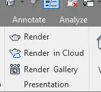
- Select scheme as a Interior: Sun and artificial, style- Few cloude
- Click on Sun setting
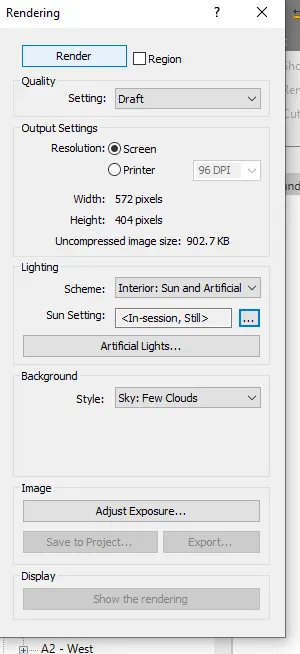
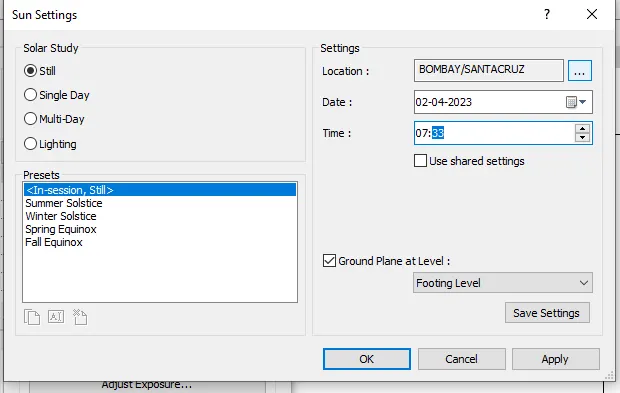
- Select still - goes on setting section clcik on location
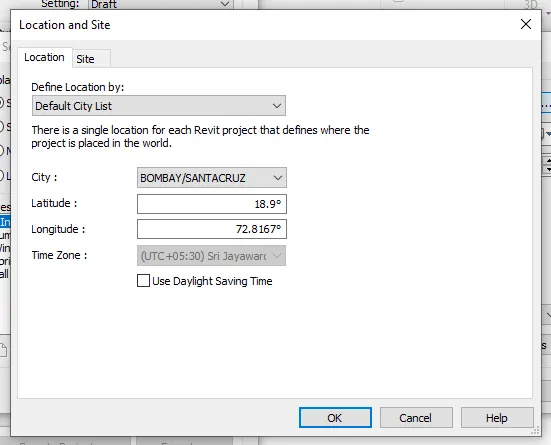
- Set default city list- select city- ok
- Then choose date and timming
- Click on Render then adjust expouser as per requirement
- Save render image by selecting the save to project.
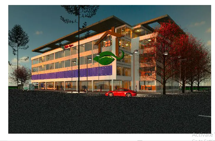
- Create other views also as similar way
- Create sheets and place them one by one
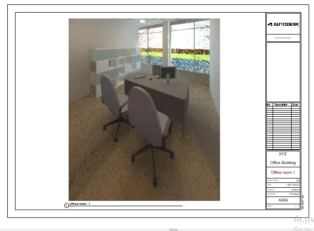
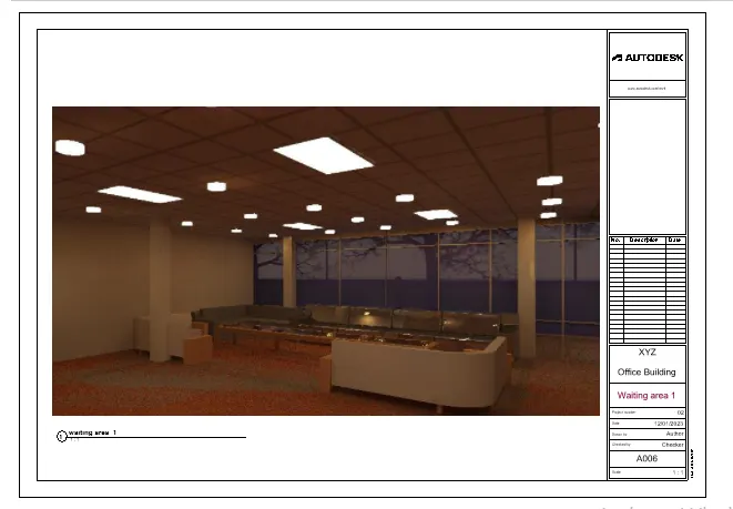
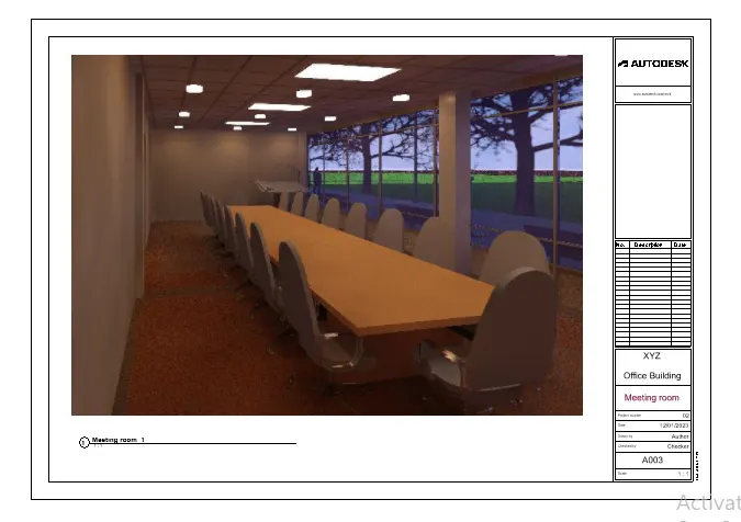
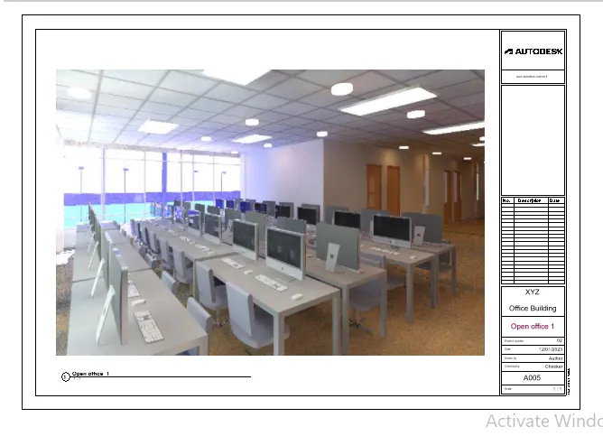
a. Rendering from interior rooms:
1)Office room:
2) Waiting area:
3) Meeting room:
4) Open office_1
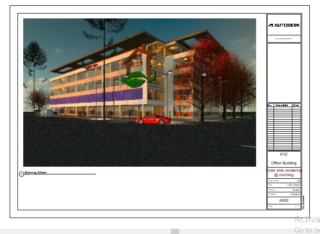
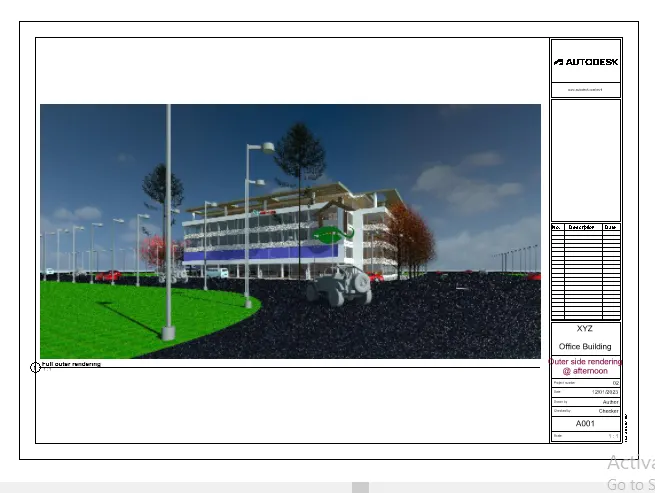
b. Rendering from out showing topographic features:
1)Outer side rendering @ Morning:
2) Outer side rendering @ afternoon:
c. Rendering through structural framing.
7) Print the set of drawing sheets created and submit the drawings from the architecture and structure model
AIM:
To print the set of drawing sheets created and submit the drawings from the architecture and structure model.
PROCEDURE:
- Click on file- select print option
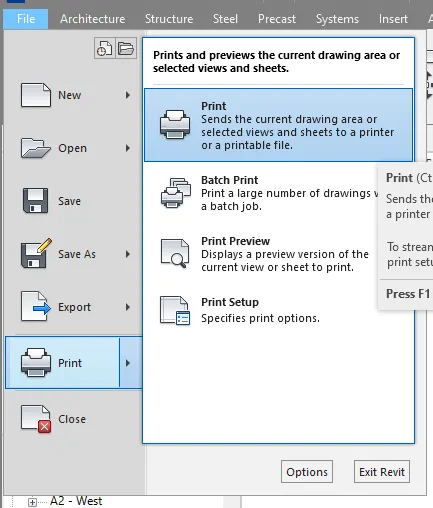
- Select name, Print range then click ok
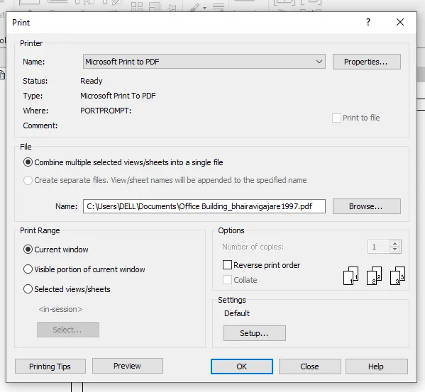
Result: Print the drawing on A1 sheet and make a bunch of drawings.
Note: I am trying to upload my project file but its size is to big due to that it is not uploaded