Creating Architectural and Structural model with 3D rendering using REVIT
7. Creating Architectural and Structural model with 3D rendering using REVIT
1) Select the type of structure you want to build from one of the three below:
a. Multi-Unit Residential Apartment
b. Office Buildings
c. School
ANS: In this drawing i have choosen School as my structure for Project.
Aim: Opening an architectural & Structural template with the Required Settings in Revit.
Tools Used: New, Browse, Save.
Procedure:
- In Revit, click the File Ribbon tab, hover the mouse over New, and then select Project.
- Select the Architectural template is in list of Project Templates, click Browse.
- In the Choose Template dialog box, navigate to the. rte file you've been working in.Click OK.
- The new "project" and give name as project 2
- Save the project.
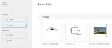
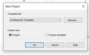
- Create the project. Use a project template provided or use a default template.
- Thus a file is now created and saved with proper information.
Similarly create a Structural template as shown above.
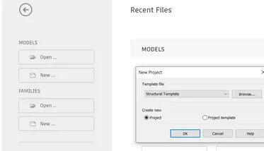
- Thus a file is now created and saved with proper information.
Result: The Templates are created and shown as above and this files is then collabrated inorder to use by different engineers. simultaneously.
2) Assume reasonable assumptions for geographic and location details for your project modeling. Based on assumptions and type of structure selected identify the modeling requirements from NBC
Aim: Creating a School Building with help of NBC in Revit.
Tools Used: Architecture toolbar, Wall, Trim, Join etc.,
Procedure:
- Open a floor plan view or a 3D view.
- Click Architecture tab then Build panel then Wall drop-down
- If you want to place a wall type other than the one displayed in the Type Selector, select a different type from the drop-down.
- You can use the bottom part of the Properties palette to modify some of the instance properties for the selected wall type before you start placing instances.
- On the Options Bar, specify the following:
- (3D views only) Select a level for the wall’s base constraint. You can choose a non-story level. See levels.
- Select a level for the wall’s top constraint, or enter a value for the default setting of Unconnected. See height and width
- In the Material Editor panel, click the Graphics tab.
- To change how the material looks in shaded views (such as 3D views and elevations), under Shading, do the following:
- If you want to use the render appearance to represent the material in shaded views, select Use Render Appearance for Shading.
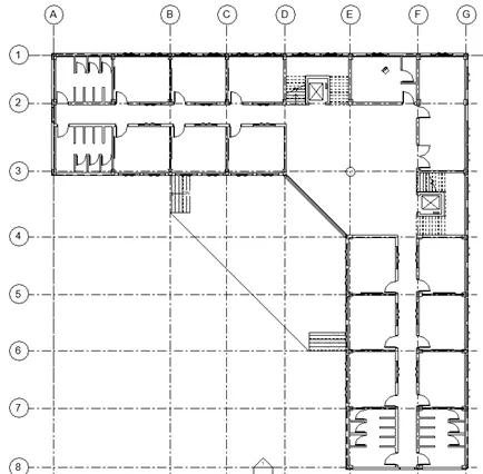
Result: The Walls are created and placed in the position along with the staircase as shown as above.
3) Using the structural model, include the following components based on the type of structure selected
a. Foundation – Isolated / Wall/Matt Foundation
b. Columns
c. Beams Connected to Columns
d. Roof Framing/ Truss
e. Floor / Decks
f. Floor Openings for Elevators and Stairs
Aim: Creating the structural model, include the All the Structural components based on the School structure in Revit.
Tools Used: Structure toolbar, Column, Beam, Footing, Trim, Join etc.,
Procedure:
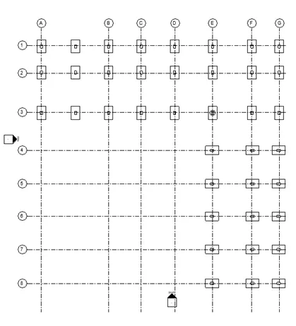
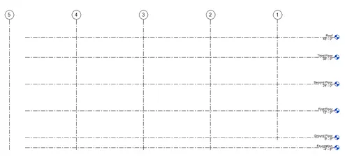
- open the structural model and start creating grids and levels as decided.
- for creating levels use structure tool bar and select level.
- now select new level and place where ever u want at particular distance as shown.
- Now start placing columns and footing by using column option in structure tab
- Selcet the column size and start placing in the required position as shown in fig
- Now copy or place column and udjust height in this case i have connected the column with levels.
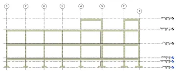
- Hence the column is created along with the footing.
- Now Similarly place the beams by using beam option.
- Select the beam and place at the required position between column as shown above.
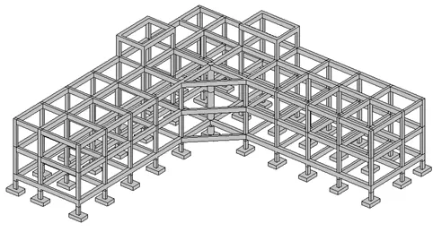
- Hence the Beamsis created along with the frame.
- Now Similarly place the slab by using floor option.
- Select the floor and place at the required position between column as shown above.
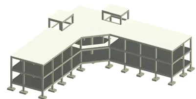
- Hence the Slab is created along with the frame.
- Now Similarly place the shaft by using vertical shaft option.
- Select the shaft and place at the required position between column as shown.
- And place in the place where u wanted to place lift as shown.
- Hence the Structural is placed as shown in figure.
- Now save the project and colabrate it by using synchronize option so that it can be used in architectural drawing.
Result: the structural drawing is created and saved with all the components like column, Footing, Beams and slabalong with shaft and is saved for future use.
4) Using the architectural model, include the following components based on the type of structure selected
a. Wall Layout with appropriate material and finishing
b. Exterior façade with fancy finish
c. Interior partition walls to size rooms
d. Components to add details to a room ( Desk, Chair, Lighting, Plumbing fixtures)
e. Add components such as stairs Elevators
f. Have at-least one side of the building with curtain walls and glass panels
g. Include interior and exterior lighting fixtures
h. Place proper topographic components from outside ( Trees, Parking, Plants) to add details to the model
Aim: Creating a architectural model of School Building with all detailings in Revit.
Tools Used: Architecture toolbar, Wall,insert, load family, Trim, Join etc.,
Procedure:
- Open a floor plan view or a 3D view.
- Click Architecture tab then Build panel then Wall drop-down
- If you want to place a wall type other than the one displayed in the Type Selector, select a different type from the drop-down.
- You can use the bottom part of the Properties palette to modify some of the instance properties for the selected wall type before you start placing instances.
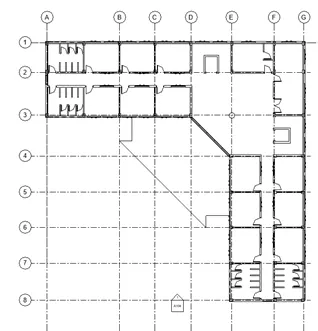
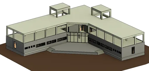
- Now select the material and copy the same to upper floors.
- use material option and give the material property to the walls.
- give different colours to the wall and front slab
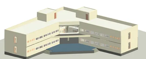
- Now add furnitures to the wall and place the lighting also.
- so that select the furniture in load family and furniture.
- select required furniture and place it where ever required
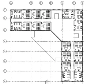
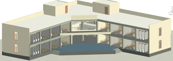
- So the furniture is then placed now time for placing the lights in the cealing.
- So that Now add lights to the cealing and place the lighting also.
- so that select the lights in load family and furniture.
- and place the light where ever required.
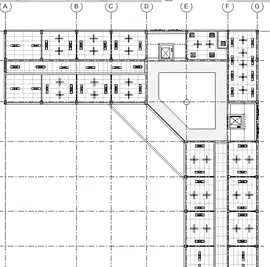
- After placing the lighting and fan now its time for curtain wall.
- so that select the wall where u want glass finish usually at the front.
- now go to setting and select the wall and select the wall as curtain as shown in fig.
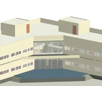
- Now lastly adding good appearance to the building by placing trees and plantation.
- select the plants fron the family.
- So the family is then placed now time for placing the lights in the cealing.
- So that Now add plants to the level and place the also.
- so that select the plants in load family and plants.
- and place the plants where ever required.
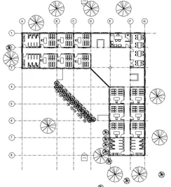
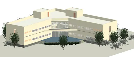
Now every this is done in architectural drawing as shown above no the only thing left is rendering the drawing in order to get proper presentation.
Result: The drawing is done the walls along with all the necesarry items are placed and shown Respectively.
5) Provide a set of drawings in an architectural and structural model to list the following details with categories and appropriate sheet templates included
a. Floor Plans with Annotations
b. Elevations
c. Sections
Aim: Creating an architectural and structural model to list the following details with categories and appropriate sheet templates in Revit.
Tools Used: Architecture toolbar, Wall,insert, load family, Trim, Join etc.,
Procedure:
- To add project templates to the Project Templates list
- Create the project templates that you want to include in the list.
- Click File tab
- Click the File Locations tab.
- Add one or more templates to the Project template files list, as follows:
- Click (Add Value).

- Click the File Locations tab.
- Add one or more templates to the Project template files list, as follows:
- Click (Add Value).
- Navigate to the project template file, select it, and click Open.
- The template is added to the list.
- The default location for project template files is: USERSPROFILE\Autodesk\RVT 2018\Templates\
- Under Name, replace the default template name with a meaningful name.
- Note:To change the template, click in the Path column, and select
- Rearrange the list to put templates in the desired order. Select a template row and use (Move Rows Up) and (Move Rows Down) to move templates to the desired position.
- The first 5 templates listed in the table will appear on the Recent Files window under Projects,
- providing quick access. When creating a project, the full list of project templates is available on the New Project dialog.
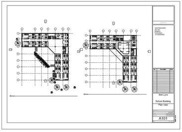
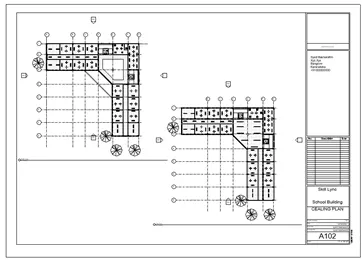
Floors plan and Cealing plan is placed with appropriet template
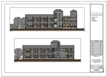
Section at A and B is placed with appropriet template :
Elevation at East West and Norts is Shown with appropriet template :
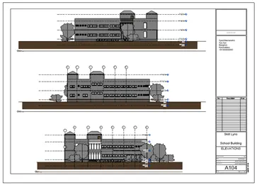
Result: The Template is Created and the views are placed along with plans Elevations and Drawing as shown above.
6) Using the Rendering settings, Render images of the 3D model produced and include the rendered images to the drawing sheets
a. Rendering from interior rooms
b. Rendering from out showing topographic features
c. Rendering through structural framing
Aim: Creating an Rendering settings, Render images of the 3D model produced and include the rendered images to the drawing sheets in Revit.
Tools Used: Architecture toolbar, view, Render etc.,
Procedure:
Revit begins the rendering process, rendering the entire image progressively. Revit displays a progress dialog, which shows information about the rendering process.
You can then do the following:

- Change render settings, and render the image again.
- Adjust exposure settings, and render the image again.
- Save the rendered image as a project view.
- Export the rendered image to a file.
- Display the building model in the drawing area.
In the Rendering dialog, click Show the model. To display the rendered image again, click Show the rendering.
- Adjust the Exposure:
After rendering an image, you can adjust exposure settings to improve the image. If you know the desired exposure settings, you can set them before rendering the image. - Exposure control setting:
Exposure control helps to convert real-world luminance values into a realistic image. - Save the Rendered Image:
After rendering a 3D view, you can save the image as a project view. In a project, rendered images display in the Project Browser under Views (all) > Renderings. You can then place the rendered view on a sheet.
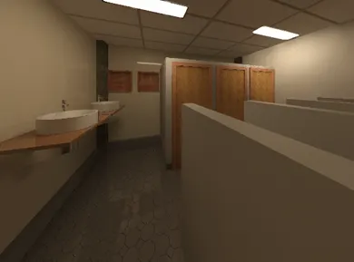
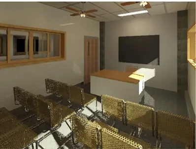
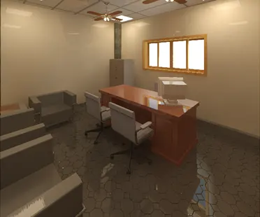
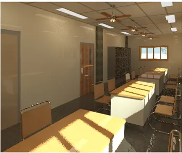
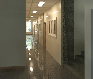
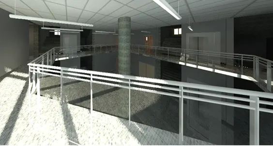
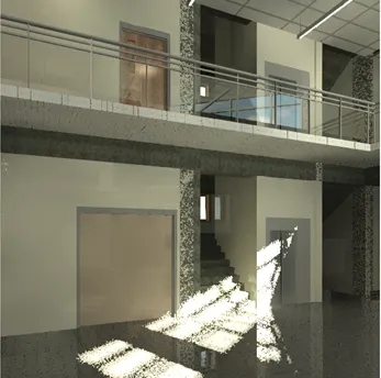
Some rendered images are attached below,
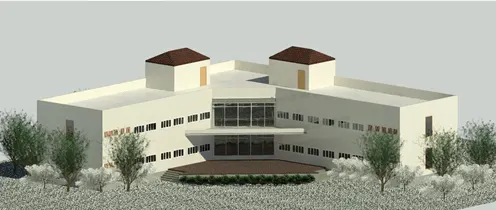
Toilet:
Class Rooms:
Office Room:
Staff Room:
Passage:
Balcony:
Stairs and Lift:
Curtain Wall:
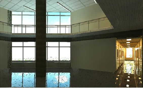
Final Image of outer
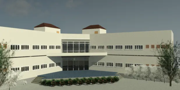
Result: the structure is being rendered and saved and the rendered images are shown above.
7) Print the set of drawing sheets created and submit the drawings from the architecture and structure model
Aim: Printing the set of drawing sheets created and submit the drawings from the architecture and structure model in Revit.
Tools Used: Print, single plot etc.,
Procedure:
- Click File tab (Print).
- In the Print dialog, for Name, select your PDF print driver.
- If the list does not include a PDF print driver, talk to your system administrator about installing one on your system.
- Click Properties.
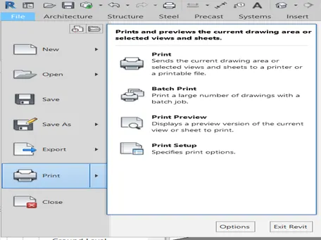
- In the Properties dialog, define settings for the PDF print driver as desired, and click OK.
- To print only the sheet or view in the drawing area:
- Under Print Range, select Current Window to print the entire view or sheet that currently displays in the drawing area, or select
- Visible Portion of Current Window to print the part of the view or sheet that currently displays in the drawing area.
- Under File, for Name, specify the name and location of the resulting PDF file. If needed, click Browse and navigate to the target folder.
- To print multiple views and sheets:
- Under Print Range, select Selected Views/Sheets.
- Click Select.
- In the View/Sheet Set dialog, select the views and sheets to print to PDF, and click OK.
- Under File, to generate a single PDF file that contains all of the selected views and sheets, select Combine Multiple Selected Views/Sheets into a Single File.
- To generate one PDF file for each selected view and sheet, select Create Separate Files.
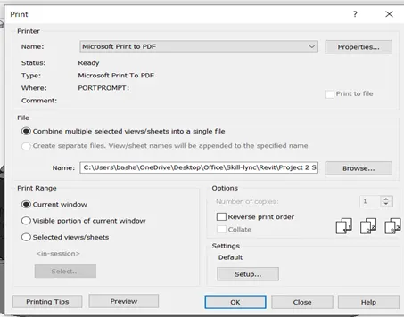
- For Name, specify the name and location of the resulting PDF file. If needed, click Browse and navigate to the target folder.
- If you are generating multiple PDF files, the specified file name is used as a prefix. It is appended with the names of the selected views and sheets.
- If you are printing multiple pages and you want them to print in reverse order, under Options, select Reverse Print Order.
- To change print settings, under Settings, click Setup.
- When you are ready to print, click OK.
- Some PDF print drivers may display another dialog requesting a location and name for the PDF file. Provide the information requested, and click OK.
Result: The drawing is now printed as shown above.