Creating Architectural and Structural model with 3D rendering using REVIT
Q.1
AIM- Type of structure which have to construct.
INTRODUCTION- We have to mention about type of structure like Commercial structure, Residential structure or other structure and it build according to NBC standard provisions.
TYPE OF STRUCTURE -
I want to model a multi-Unit Residential appartment Appartment in a Small town.
Q.2
AIM- Select geographic and location details for your project modeling and what type of NBC standards are requirement for construct a multi-unit residential apparment.
INTRODUCTION- For the construction of multi-unit residential apparment construction all the standard data from NBC taken for the safety and sustainability purpose.
DATA FROM NBC FOR CONSTRUCTION MULTI-UNIT RESIDENTIAL UNIT-
- Open space around the building shall not be less than 4.5m, in this model i have taken 1 acre field area so space is within the prescribed limits as per NBC.
- The type of construction 1, the FAR value for the residential building shall be taken UL for residential multi-unit project. So plot size of my project i.e 51'x72' FAR value will be within prescribed limits as per NBC.
- FAR VALUE
total covered area of all floors/ plot area
- The width of road is taken as 30' or 9m.
RESULT- All the standards are taken from NBC for the construction of multi-unit residential appartment.
Q.3
AIM- Using the structural model and add the different structural component in multi-unit residential appartment.
INTRODUCTION- In structural model after adding the structural component a frame of column and beam will make.
PROCEDURE-
- Firstly we will open the structural model.
- In structural model firstly we will set the grids and level under the architectural tab edit the number and name respectively.
- Now we will add the footing at grids intersections under the structural tab and will select isolated footing and add it on grids.
- Same as column will also select under the structural tab add it on grids.
- Now beam of proper dimension we will add on column under structure tab.
- After adding column and beam at ground floor now we will drart a floor on beam under the architectural tab, we will select the outer line of beams and will draw the floor.
- Now we added all the structural component on ground floor like footing, column, beam and floor, next we add all the structural components on all level.
- We will select the whole ground floor model and copy it under modity tab and after that we will paste according to level like first floor level, second floor level and roof level etc.
- In this way we will obtained a frame structure of footing, column and beams.
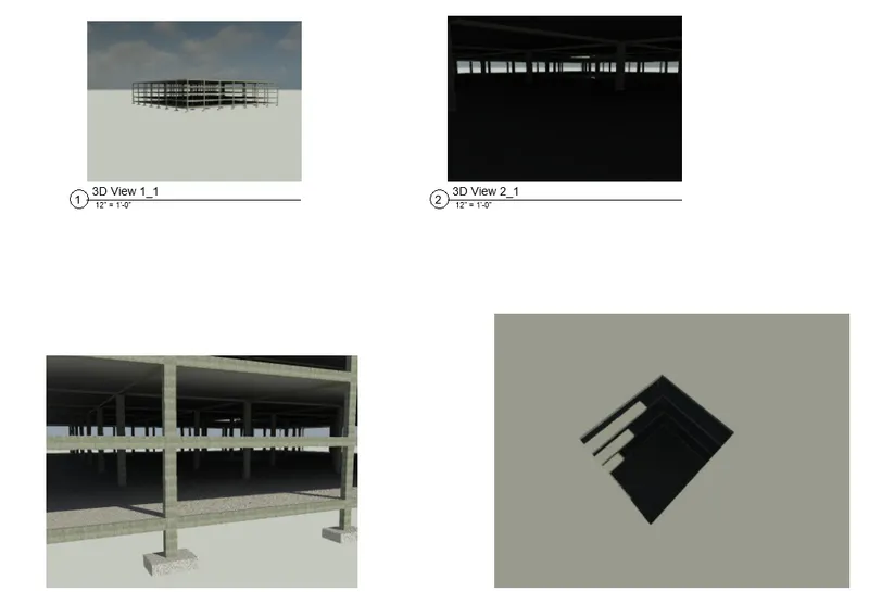
RESULT- Structural component like footing, column, beam etc. selected under the structural tab and added all structural component at grids.
Q.4
AIM- With the use of Architectural model add the different architectural component into the architectural model.
INTRODUCTION- This architectural model include different component like Wall layout with appropriate material, Exterior facade with fancy finish, Stairs elevators etc.
PROCEDURE-
- Open the architectural model.
- Draw outer boundary wall of residential building under the architectural tab and set it bottom and top constraints.
- Now we will add the appropriate material into the outer wall under the property browser.
- Next we will draw the partiton wall under the wall category and will seperate the rooms like bedroom, kitchen, rest room, toilet, dinning etc.
- Now we will add the interior components into the rooms like chair, dinning table, study table, sofa, kitchen items, plumbing fixtures under the autodesk revit family.
- we will create the shaft opening for stair and elevators under architectural tab and will choose shaft icon, in this shaft opening now we will add the stairs under architectural tab and we will also set the stairs top and bottom constraints.
- To provide a curtain wall we will choose curtain wall under architectural tab and we will provide it at certain location.
- We will also add street light under the revit family we will choose street light under the lighting fixture.
- At the last step we will provide topographic components under Massing and Site tab like trees and we will also provide parking area for vehicle under the revit load family.
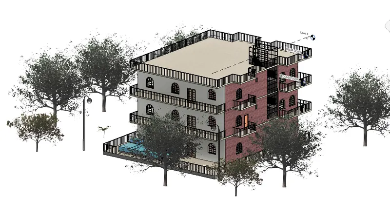
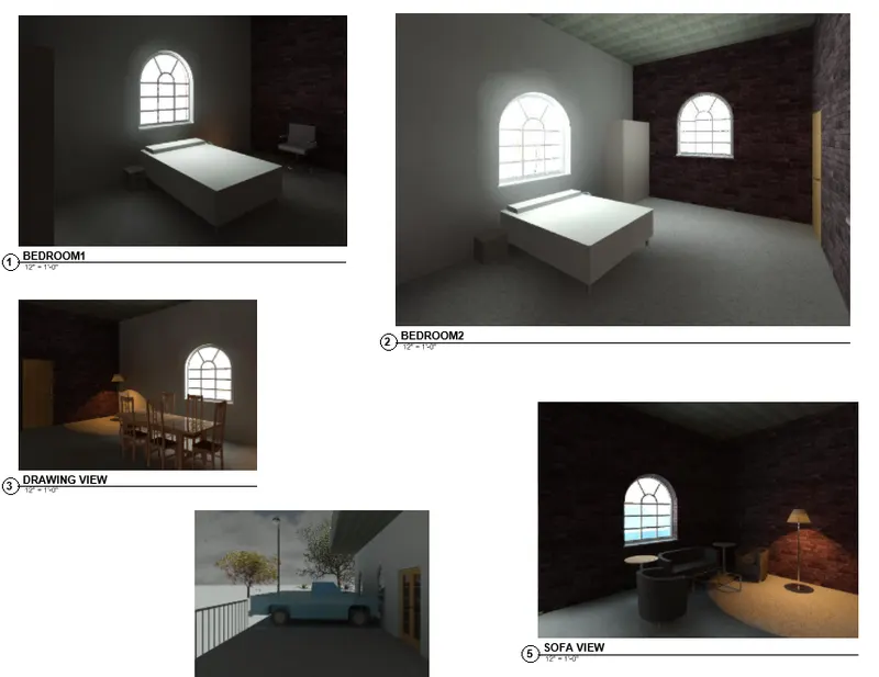
RESULT-
In this architectural model architectural component like lights, chairs, table, plumbing fixtures and parking etc, provided under the autodesk load family.
Q.5
AIM- Set the architectural and structural drawings in appropriate sheet templates.
INTRODUCTION- The architectural and structural template include Floor plan with elevation, Elevations views and Sections.
PROCEDURE-
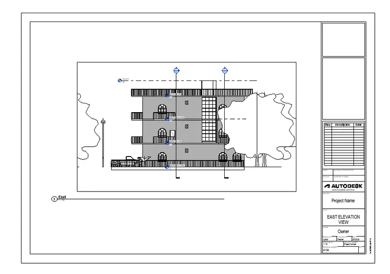
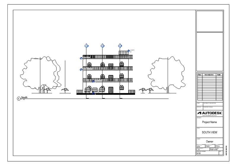
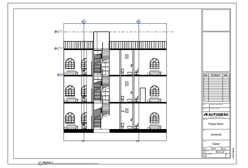
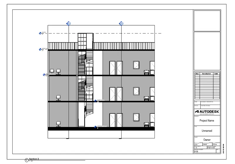
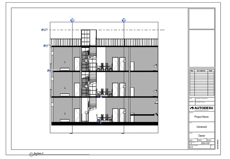
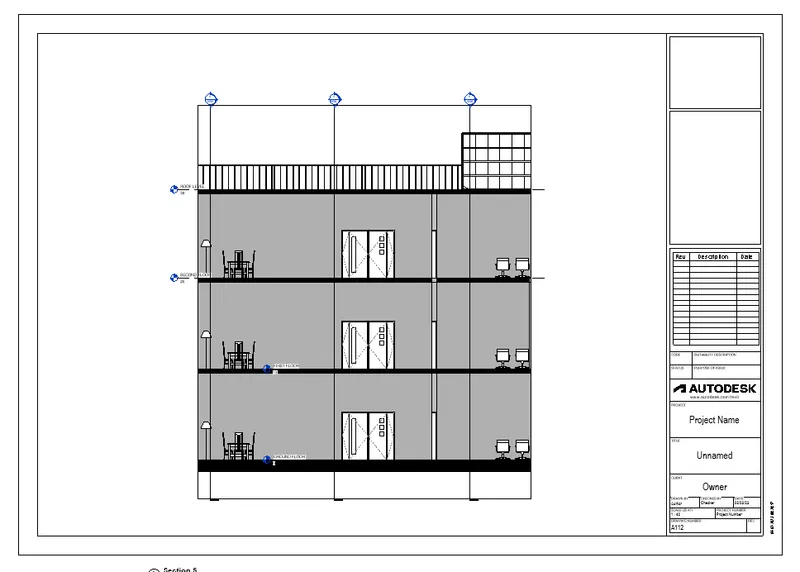
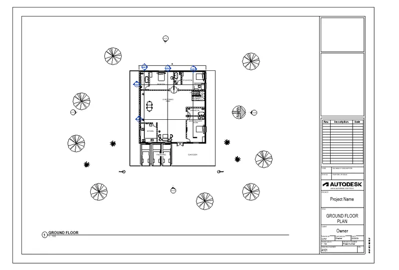
- For adding the different view in sheet firstly we will select the sheet under view tab and choose the metric sheet and drag the views into the sheet.
STRUCTURAL SHEETS-
There is problem to show the structural view under the view tab it also show the architectural components into the structural view i also cressed checked by tutor but the same problem faced by tutor.
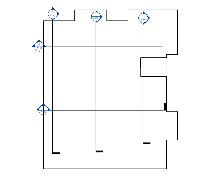
ARCHITECTURAL VIEW-

SECTION VIEWS-
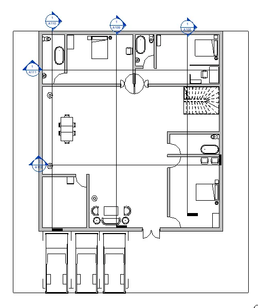
Floor plan with annotations-
RESULT-
All the view like elevation view, section view etc insert into the sheet under the view tab.
Q.6
AIM- Produce the render views of 3D view and insert the 3D rendered views into the sheets.
INTRODUCTION- The produced rendered view is interior rooms rendering, topographic features rendering and rendering of structural framing.
PROCEDURE-
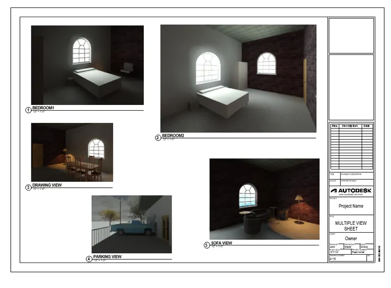
- firstly we will set the cameras in rooms to take the 3D inside view of room under the view tab.
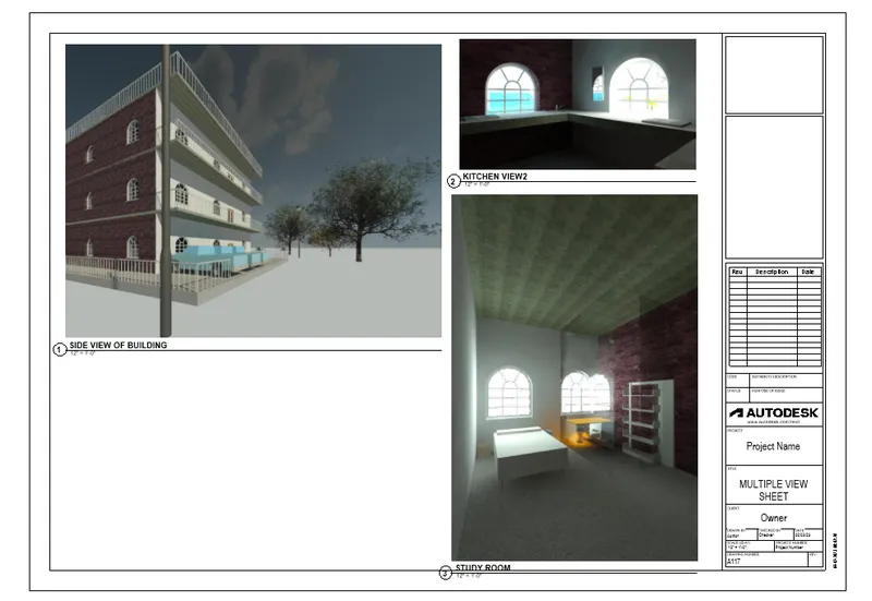
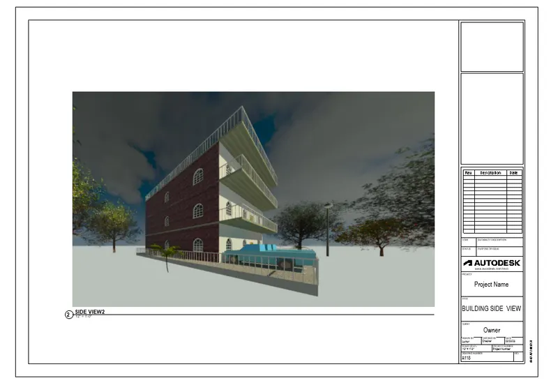
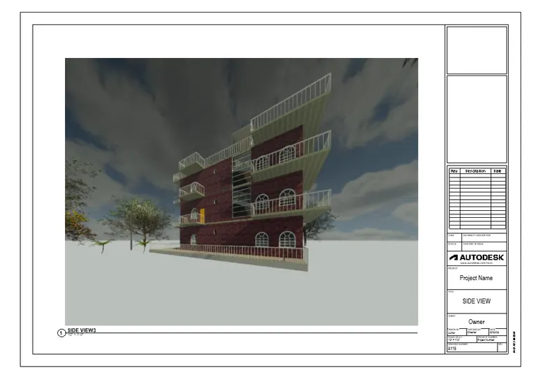
- same as we will also set the cameras under view tab outer of the building and take the outer topographic view of building.
- Structural 3D view also take as the same process which is described above.
- Now we will render all views like interior view, outer topography view and structural framing view under the view tab and we will setting the render view under render icon like image quality draft, medium and hight and exposure condition etc.
- Rendered views will also insert into the sheets under view tab and sheet icon.
RENDERING FROM INTERIOR ROOMS AND OUTSHOWING TOPOGRAPHIC FEATURES-
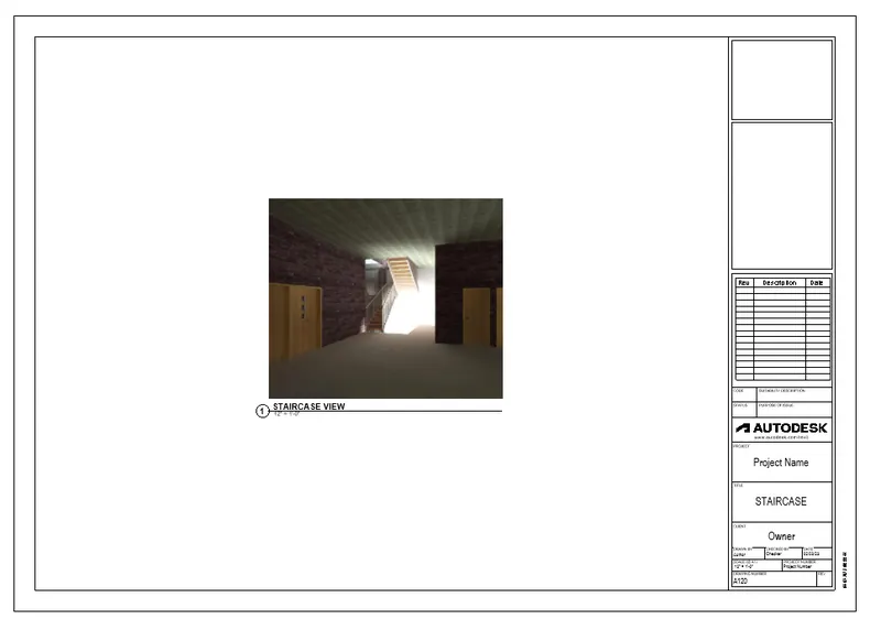
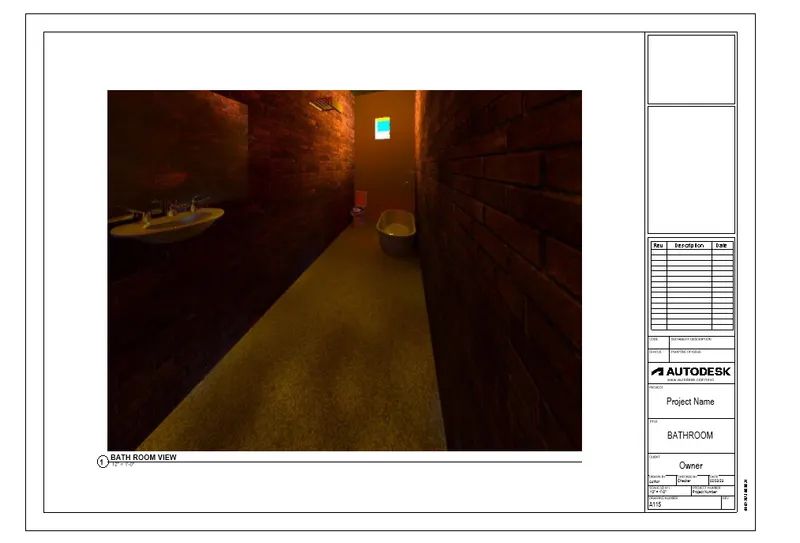
RENDERING OF STRUCTURAL FRAMING-
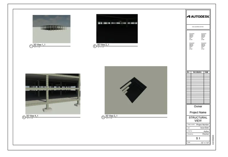
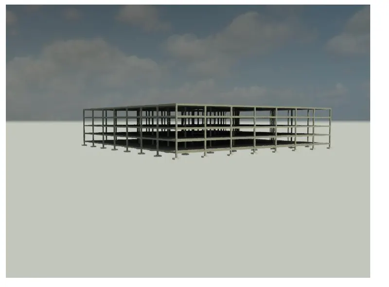
RESULT- Camera is set under view tab, 3D VIEWS render under view tab and sheet is created under the view tab and sheet icon and all the render views inseted into the sheet by drag method.
Q.7
AIM- Print the drawing sheets which is created from architectural and structural model.
INTRODUCTION- Architectural and structural sheet printed on a A4 or A3 size paper or saved it as a PDF for export the drawing at site and for error free work.
PROCEDURE-
- firstly choose the approprite model view like structural or architectural.
- inter ALT plus P to print this model and save the setting like size of paper, orientation of paper, pdf or printer option etc.
- For pdf save it as appropriate name.
RESULT-
For print of Architectural and structural sheet drawings Ctrl + P keys used and print it or save it as appropriate name.