Creating Architectural and Structural model with 3D rendering using REVIT
1) Select the type of structure you want to build from one of the three below:
a. Multi-Unit Residential Apartment
b. Office Buildings
c. School
Ans : The type of structure want to build is multi - unit residential apartment
2) Assume reasonable assumptions for geographic and location details for your project modeling. Based on assumptions and type of structure selected identify the modeling requirements from NBC
Ans :
- The road width of the project is 60'
- The height and area limitation and safety measure as per NBC 2005
- The height of the project is 40' .
- The project height in meter is 12.1m and the road width is 18.2m , The height of th building should not exceed 1.5 times the width of the road .
- The build height are not exceed so it is suitable for the construction .
3) Using the structural model, include the following components based on the type of structure selected
a. Foundation – Isolated / Wall/Matt Foundation
b. Columns
c. Beams Connected to Columns
d. Roof Framing/ Truss
e. Floor / Decks
f. Floor Openings for Elevators and Stairs
Ans :
- Creating the coordinates for the project
- Open the architecture templet
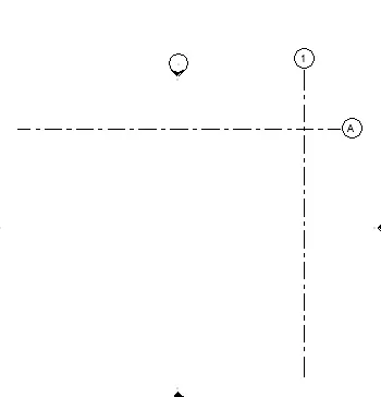
- And Give the grid lines in the architecture tab and Rename the grid lines
- And Open the manage tab
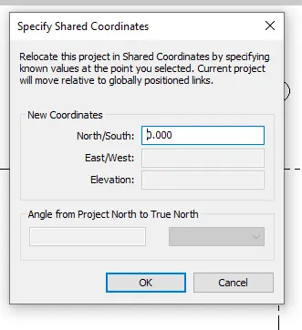
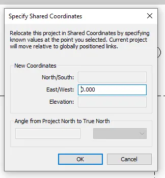
- Click on project coordinates and go to the specific shared coordinates
- And Give the north/ south type 0'0"
- In east /West type 0'0"
- And Go to the visiabilty graphic and go to site and select the project base point
- And specfiy coordinate at a point and select the grid lines
- Open the architectural template file in revit
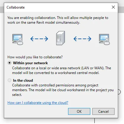
- And go to the collaboarte tab and select the collaborate
- and select the with in your option and give the ok for it
- Go to the structural template
- open the any elevation and give the level for the project give the level as the foundation ,ground,first,second ,thrid and roof floor level
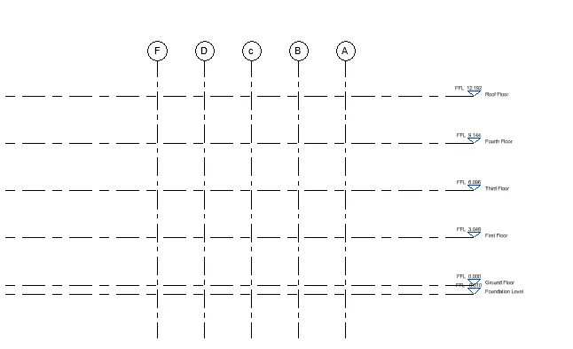
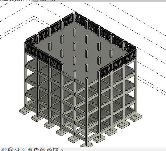
- And Go to the foundation level and go the structure tab and select the isolated footing and select the grid to be placed and select the all grid lines and place footings as per the grid lines intersect.
- And go to the ground floor level and open the structure tab and select the column and select the grid to be placed and select the all grid lines and place the column as per the grid line intersection .
- and give the height of the column from the ground floor to the roof floor level
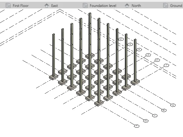
- select the ground floor level and go to the structural tab and select the beam from it and as per the grid
- Then select the entire grid lines and places beam as the grids .
- as per this they beam are connected to the column in it
- and repeat the process to connect the beams for the remaing floors .
- Select the floor from the architecture or structure tab and open the ground floor and draw the rectangle and then give the tick mark to from the floor the ground floor .
- repect the process for the floor for the remaing floors .
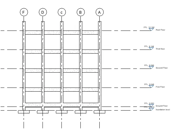
- And in the structural tab select the sharft and give the opening for the elevators and staircase for the floor .
- and save the project to the central file
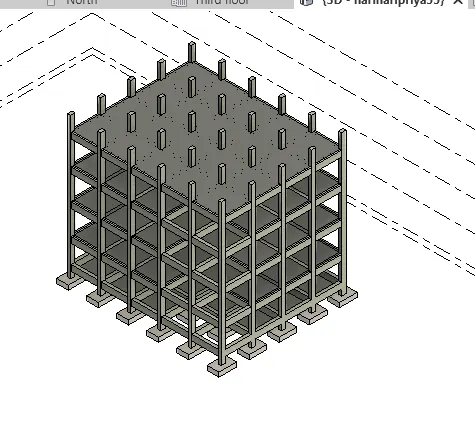
- Go to the structure tab and select the roof framing /truss and go to the roof floor level and give the truss member to it .
4) Using the architectural model, include the following components based on the type of structure selected
a. Wall Layout with appropriate material and finishing
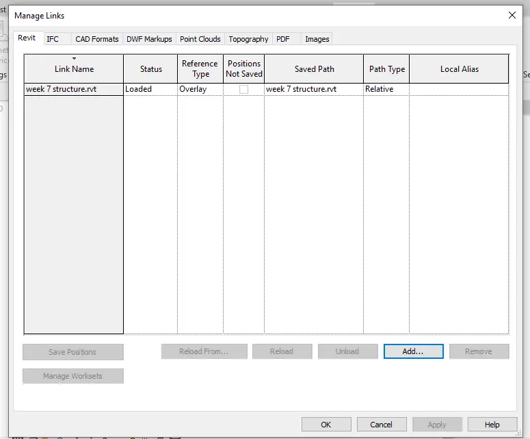
- open the architectural template which we created
- copy the grids which we created in the structural template and copy it
- with the copy paste tool fron the clipboard in the architecture template
- and pin the grid lines and open the elevation level and give the floor level in the architeture
- Using the graphics setting and select in annoatation off the the grids .
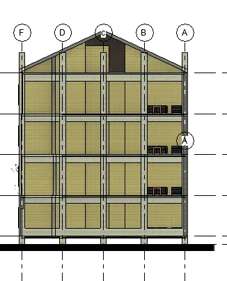
- And then create the exterior wall on the grid lines
- and give the walls for the levels of the project
b. Exterior façade with fancy finish
- Using the propertie edit for the wall and give the material properties for the project for the exterior finish
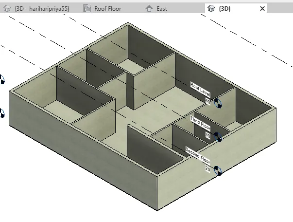
c. Interior partition walls to size rooms - And using the wall from the architeture tab and give the interior partition walls as per the room sizes
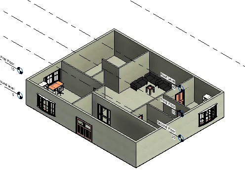
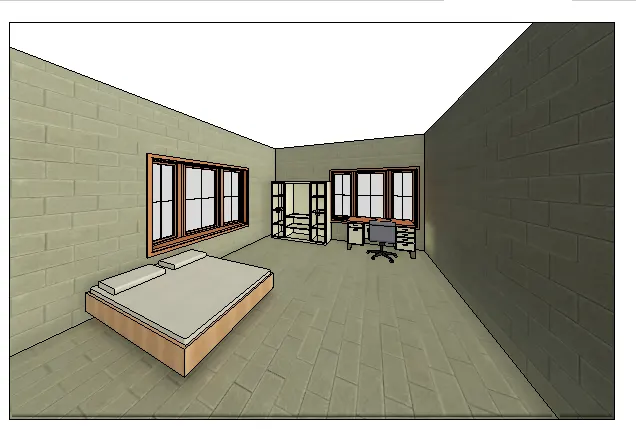
d. Components to add details to a room ( Desk, Chair, Lighting, Plumbing fixtures) - select the components and add the details for the each room the load familes of the components
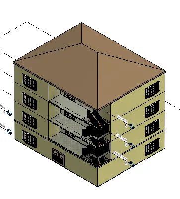
e. Add components such as stairs Elevators - select the staircase from the architeture tab and it draw it using the various types of staircase which we requred and tick the staircase .
- it draw in the ground floor and give the height of the floor level to the draw the staircase .
f. Have at-least one side of the building with curtain walls and glass panels - from the wall we can select the curtain wall and also give the curtain walls and glass panels as per the required .
g. Include interior and exterior lighting fixtures - And give the lighting fixtures for the interior and exterior using the render elements and fix the lighting fixture
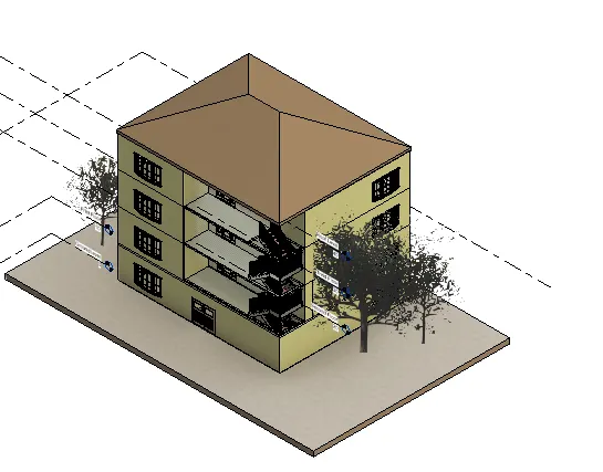
h. Place proper topographic components from outside ( Trees, Parking, Plants) to add details to the model
- Select from the manage site tab and and give trees ,parking , and plantes for the models .
5) Provide a set of drawings in an architectural and structural model to list the following details with categories and appropriate sheet templates included
a. Floor Plans with Annotations
b. Elevations
c. Sections
Ans :
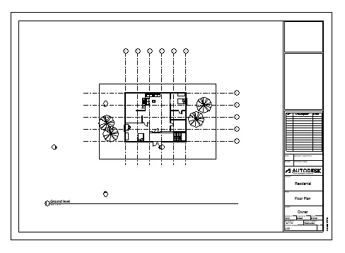
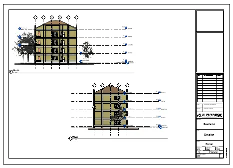
- open the view tab and select the sheet tool
- And select the A1 metric sheet the sheet dialog box and give ok
- And rename the sheet names using the double on the text or using project broswer infromation
- Add the floor plan in the sheet go to the project projecties and drag the floor plan and plan in the sheet .
- Repeat the same process for the both elevation and section is place in the sheet .
6) Using the Rendering settings, Render images of the 3D model produced and include the rendered images to the drawing sheets
a. Rendering from interior rooms
b. Rendering from out showing topographic features
c. Rendering through structural framing
Ans :
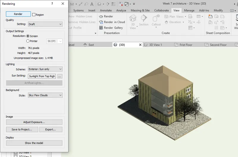
- Open the 3d view and set the view and go to the render to the area
- select the view menu and click the render
- then the render dialog box are appears
- select the region option and drop the image in region
- if we required change the style of render images , schemes , lighting ,and then render to it .
- the render image will be appers into more realistic and use it in the presentation .
7) Print the set of drawing sheets created and submit the drawings from the architecture and structure model
Ans :
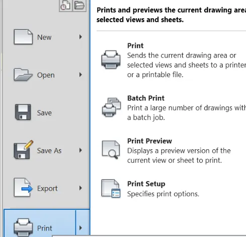
- Open the file tab menu
- the print option will appear on it click on it print dialog box will be appear
- change the seetings of sheet sixe and text style and page setups
- and then click to give the print.
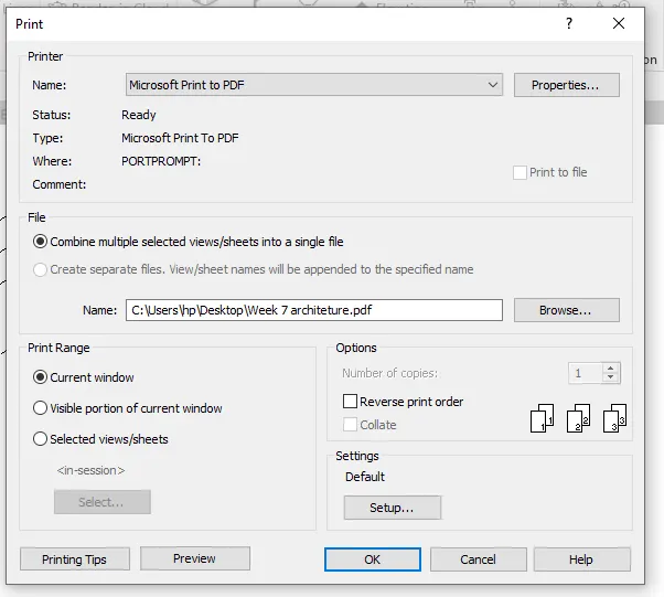
drawing sheets created and submit the drawings from the architecture and structure model