Creating Architectural and Structural model with 3D rendering using REVIT
Answer to the question No.1
Question: Select the type of structure you want to build from one of the three below:
a. Multi-Unit Residential Apartment
b. Office Buildings
c. School
Answer:
Aim: Aim of the question is to build structure building given.
Introduction: in this project i am goint to create multi unit residential structure to build a building. we have to assuming some assumptions for geographicaal and location details for my project modeling. Based on assumptions and type of structure selected identify the modeling requirements from NBC.
Procedure: TO COMPLETE THE ANSWER TO THE QUESTION WE FOLLOW THE FOLLOWING STEP:
Step-1
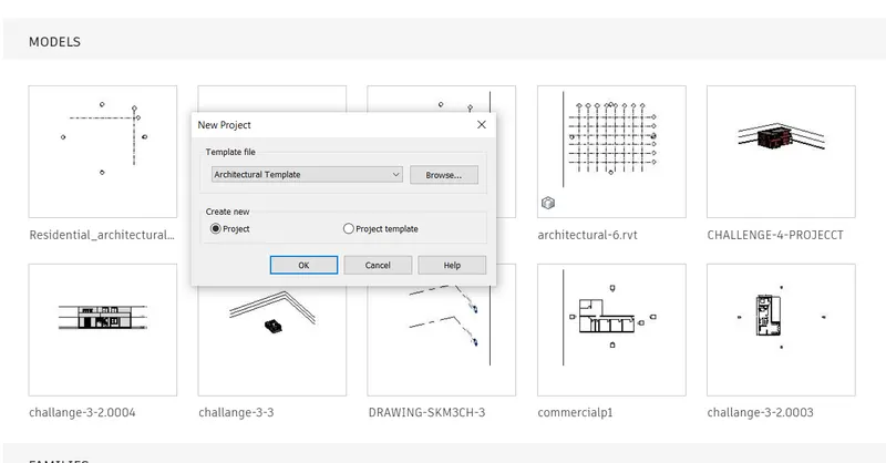
- First of all open the architectural template in Revit software and and save this with the appropriate name 0------------
Step-2
- Click on the architectural tab. and add an architectural component
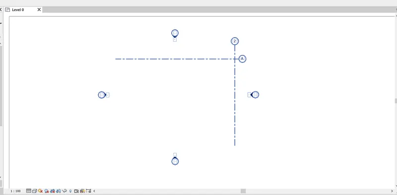
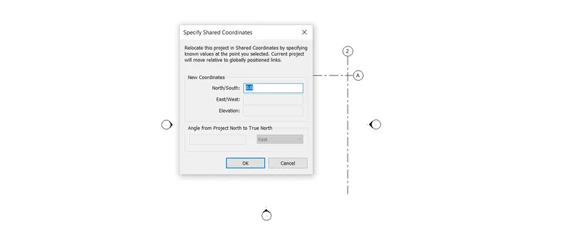
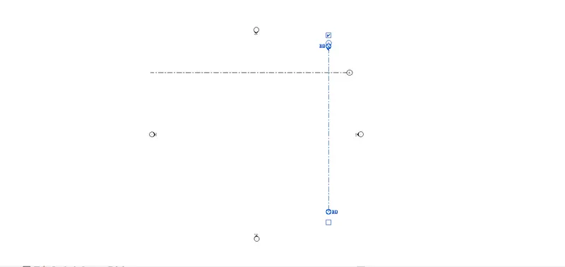
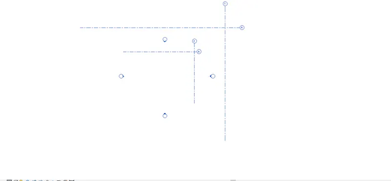
- draw the grid lines and specify coordinates as 0'0" from both grid horizontal and vertical and put name 1 for vertical and A for horizontal grid.
Step-3
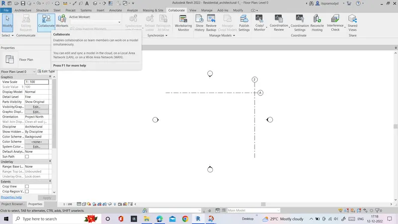
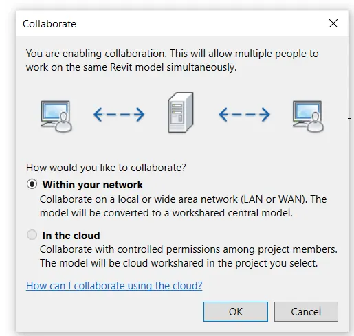
- Now go to collaborate tab and click on the collaborate option save the project.
Step-4
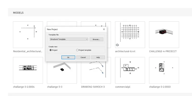
- Click on the structural tab and add structural component
- Go to new tab and click on the structural tab save thi with the appropriate name ------------------
Step-5
- Again go to
Step-6
- Again create a new Architectural template with the appropriate name.
Step-7
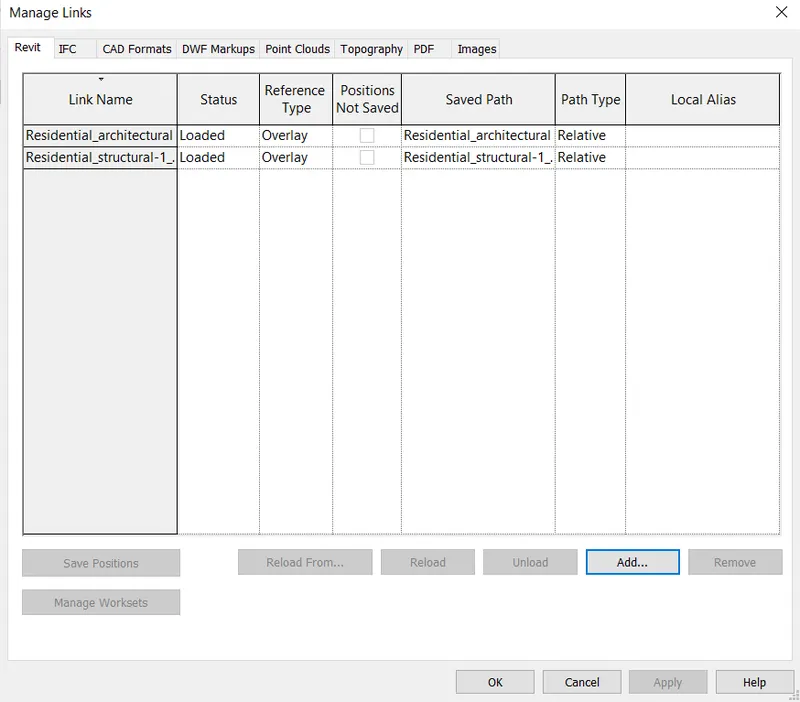
- Add the architectural and structural links using manage the link options.
Step-8
After loaded architectural and structural template.
Step-9
- Now select acquired coordinates and set the links to the current coordinate.
- Go to the manage tab select the project location and set the
Step-10
- Now open the structural template which we made before,
- Verify levels after clicking the property browser.
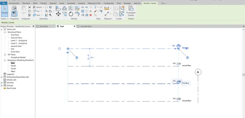
- Rename the ground floor and other floors and put the height 12'
- Create first floor level second floor level third floor level and roof level
Step-11
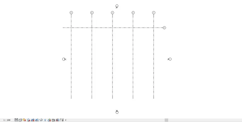
- Go to ground floor and create remaining grid lines. create 30' from each
- We are creating verical grrid .
Step-12
- Also creating the remaining horizontal grid by using structrasal tab and grid
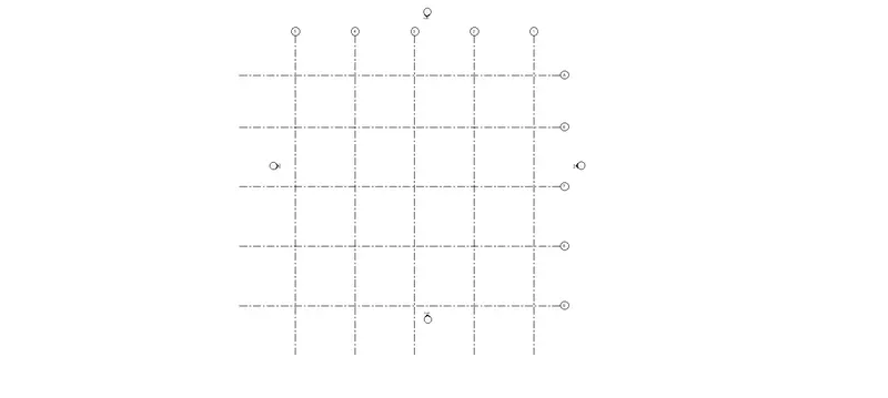
Step-13
- After completion of this we are adding the structural column beam , and foundation.
- Go to east view and and another level for foundation with the distance of 4'6" or design engineer.
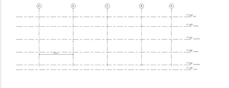
Step-14
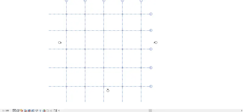
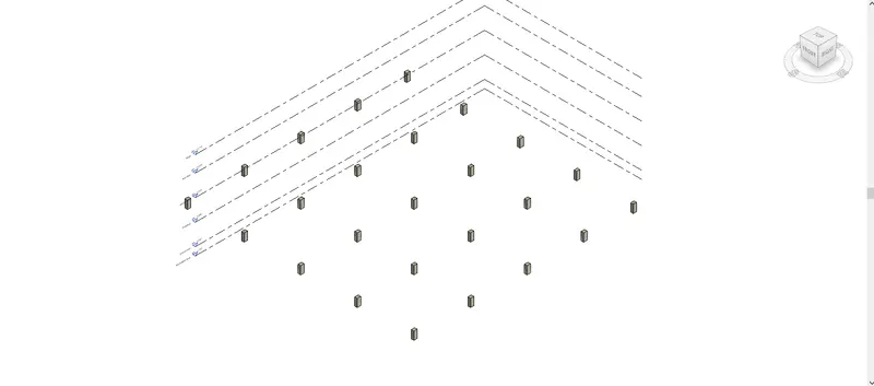
- Now we are adding the column.
- to adding the column first of all go to groundfloor plan
- and click the structural tab
- click the column and select the size by property brouser.
- put is at the grid option.
3D view:
Step-15
- Now we are trying to putting the first flor column.
- For first-floor column go to the structural tab.
- Select the column select height and first-floor option
- select at the grid and put the column.
- Check 3d view
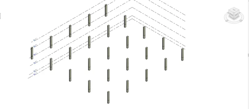
Step-16
- Put the Arhitectural column with the help of structural tab
- Architectural column put at the boundary column or where it is required.
- after this deleted unwanted columns.
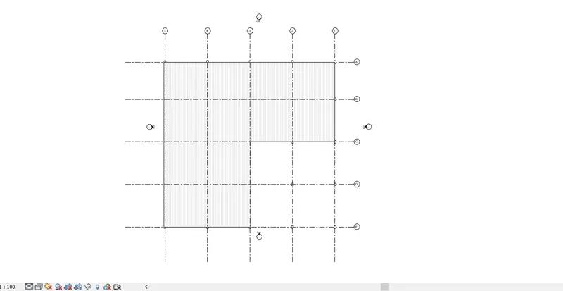
Step-17
- After putting the column we are trying to put the beam at the model.
- click the structural tab. after this, we are going to.
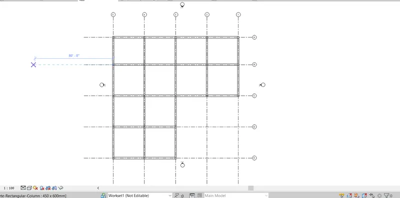
3D view:
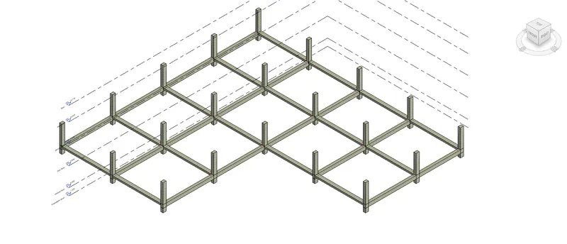
Step-18
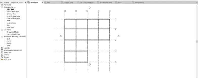
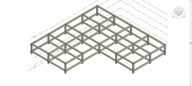
- Now we adding the first floor beam with the help of structural tab.
- We are putting the first floor beam with the help of structural tab .
3D view:
Step-19
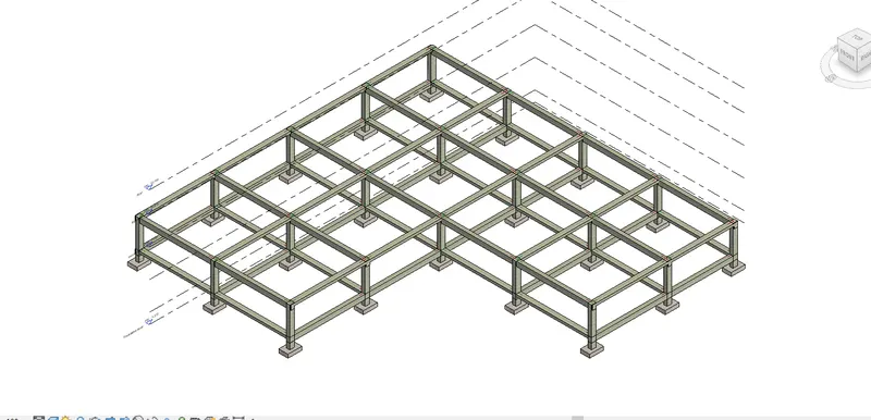
- Now w are trying to put the isolated foundation
- click the structural tab
- click the isolated
- and select the foundation size.
- put its foundation level.
- after this to put the level we will create the floor and
- Copy the element and put it by the filtering option.
Step-20
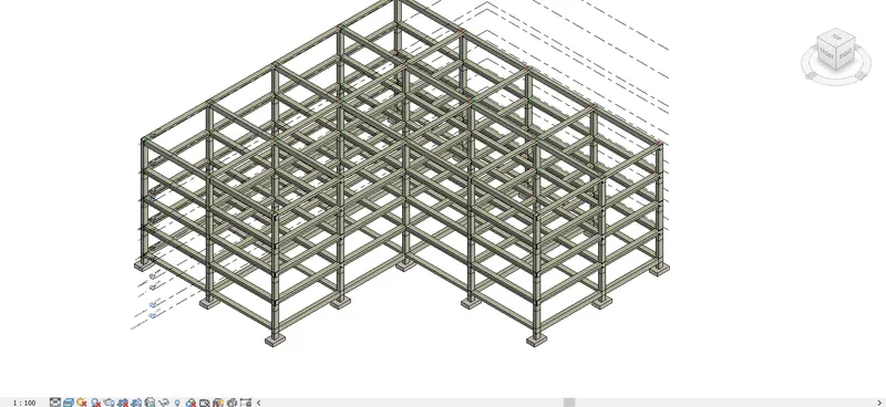
- Now go to 3d view of the building and select all the elemnt
- Click on the filter unselect the foundation and anlytical foundation.
- goto copy to clipboard
- and pase to the levels
Step-21
- We aare startingto creating the floor
- For the floor goto structural tab
- click structural floor
- and take line and draw
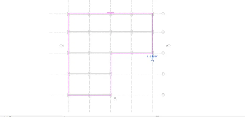
Step-22
- After drawing the floor we are copying the floor to the other levels
- select the floor
- click the copy to clipbord
- past to the alinged lvelslevel
- select the first floor , second floor and third floor
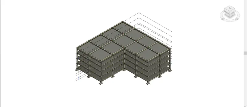
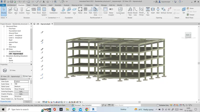
another view:
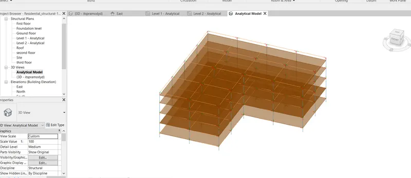
Analytical Model:
RESULT: I HAVE CRETED ALL GIVEN STRUCTURE MODEL. IN ARCHITECTURAL PLAN AND STRUCTURAL PLAN OF THE BUILDING IN THIS QUESTION WE WILL USE COLLABORATION WITH THE HELP OF REVIT SOFTWARE. AFTER GIVING THE ANSWER TO THE QUESTIONS SCREENSHOTS ARE ATTACHED WITH THE RESULTING DRAWING.
Model drawing Screenshot:
Answer to the question no-2
Question: Assume reasonable assumptions for geographic and location details for your project modeling. Based on assumptions and type of structure selected identify the modeling requirements from NBC
Answer:
Aim :Assume reasonable assumptions for geographic and location details for your project modeling. Based on assumptions and type of structure selected identify the modeling requirements from NBC
Introduction:The office building is planned to be constructed in commercial IT park area in Kochi.
Modelling requirements as per NBC-
Since, my building is an office building, it can be taken as a business building.
- The open space around the building shall not be less than 4.5m.
2. Considering the type of construction as type 2 construction , the FAR value for the business building shall be taken as 2.9. The plot size is taken as 40mx70m i.e, 2800m2">m2m2 and individual floor area is 2000m2">m2m2. Hence, FAR value obtained is 2.14 which is within the prescribed limits as per NBC.
3. The width of the road abutting the building is taken as 9m (30').
4. The maximum height of the building shall not exceed 1.5 times the width of road abutting plus the front open space. Building will consist of 3 floors each floor having a floor height of 3.6m. Hence, the entire floor height will be 10.8m, which is within the limits prescribed by NBC.
RESULT:i write all the Assume reasonable assumptions for geographic and location details for your project mode ling. Based on assumptions and type of structure selected identify the modeling requirements from NBC
Answer to the question No.3
Question:
Answer: Using the structural model, include the following components based on the type of structure selected
a. Foundation – Isolated / Wall/Matt Foundation
b. Columns
c. Beams Connected to Columns
d. Roof Framing/ Truss
e. Floor / Decks
f. Floor Openings for Elevators and Stairs
Aim:Using the structural model, include the following components based on the type of structure selected
a. Foundation – Isolated / Wall/Matt Foundation
b. Columns
c. Beams Connected to Columns
d. Roof Framing/ Truss
e. Floor / Decks
f. Floor Openings for Elevators and Stairs
Introduction: in the last question we have to all the creted all the component in the building.
Procedure: TO COMPLETE THE ANSWER TO THE QUESTION WE FOLLOW THE FOLLOWING STEP:
Step-1
- In this question we have to create the first of all we have to create the architectural template for model. and collaborate this by in your nework option.
- after this we have to completed the structural template of the model collaborate this in your network option.
- finally creted the combinde template of the model and collaboratecollaboration with collaborate tab
- in the combine template link all the structural and architectural template
Step-2
- Open structural model and crete levels. by clicking east.
- Now we have to created the levels .
- Created Foundation, Ground floor, First floor ,Second floor , Third floor and Roof
Step-3
Foundation:
- Now we are adding the Foundation column.
- to adding the column first of all go to groundfloor plan
- and click the structural tab.
- click the column and select the size by property brouser.
- put is at the grid option.
Foundation Column
3D view:
Step-4
b. Columns
- Go to first floor by Property browser and add some column and put the isolated footing foundation by the structural tab
- Now we are trying to putting the first flor column.
- For first-floor column go to the structural tab.
- Select the column select height and first-floor option
- select at the grid and put the column.
- Check 3d view
Step-5
- Put the Architectural column with the help ofthe structural tab
- Architectural column put at the boundary column or where it is required.
- after this deleted unwanted columns.
Step-6
c. Beams Connected to Columns
- After putting the column we are trying to put the beam at the model.
- click the structural tab. after this, we are going to.
3D view:
Step-7
- Now we adding the first floor beam with the help of structural tab. and also put the connected beam.
- We are putting the first floor beam with the help of structural tab .
3D view:
Step-8
- Now w are trying to put the isolated foundation
- click the structural tab
- click the isolated
- and select the foundation size.
- put its foundation level.
- after this to put the level we will create the floor and
- Copy the element and put it by the filtering option.
Step-9
- Now go to 3d view of the building and select all the elemnt
- Click on the filter unselect the foundation and anlytical foundation.
- goto copy to clipboard
- and pase to the levels
Step-10
d. Roof Framing/ Truss
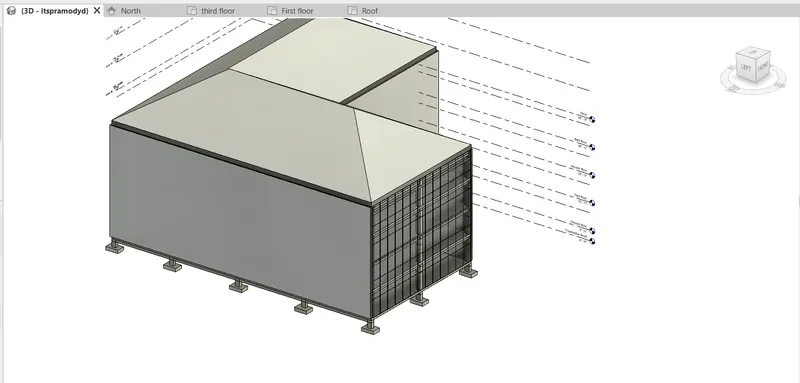
- Now we are adding the roof in the model
- to adding the roof goto the architectural tab
- select roof
- go to roof by footprint
- now draw the roof by line or pick line than finish
- provide the slop 30degreee
Step-11
e. Floor / Decks
- we are starting creting the floor
- for all the floor go to structural tab
- click structral floor
- and take line and draw
Step-12
- after drawing the floor we are copying the floor to the other levles
- select the floor
- click the copy to clipbord
- past to the alinged lvelslevel
- select the first floor , second floor and third floor
another view:
Step-13
f. Floor Openings for Elevators and Stairs
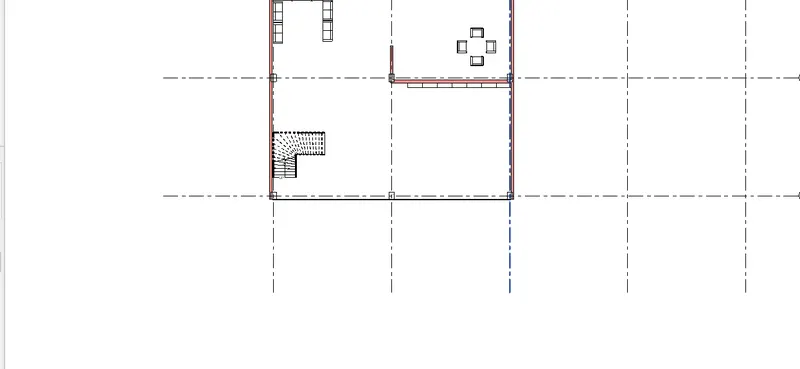
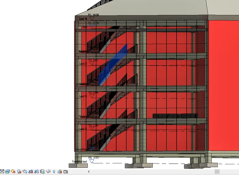
- we are adding the staire with the help of architectural staire
- Add this to the first floor
- and select the component and add the staire the all the floor.
3D view:
RESULT: I HAVE CRETED ALL GIVEN STRUCTURE MODEL. we created column , beam , foundation etc.IN ARCHITECTURAL PLAN AND STRUCTURAL PLAN OF THE BUILDING IN THIS QUESTION WE WILL USE COLLABORATION WITH THE HELP OF REVIT SOFTWARE. AFTER GIVING THE ANSWER TO THE QUESTIONS SCREENSHOTS ARE ATTACHED WITH THE RESULTING DRAWING.
Answer to the question No.4
Question: Using the architectural model, include the following components based on the type of structure selected
a. Wall Layout with appropriate material and finishing
b. Exterior façade with fancy finish
c. Interior partition walls to size rooms
d. Components to add details to a room ( Desk, Chair, Lighting, Plumbing fixtures)
e. Add components such as stairs Elevators
f. Have at-least one side of the building with curtain walls and glass panels
g. Include interior and exterior lighting fixtures
h. Place proper topographic components from outside ( Trees, Parking, Plants) to add details to the model
Answer:
Aim: Assume reasonable assumptions for geographic and location details for your project modeling. Based on assumptions and type of structure selected identify the modeling requirements from NBC
Introduction: to using the arcgitecturl model, include the following components based on the type of tructure above.
Procedure: TO COMPLETE THE ANSWER TO THE QUESTION WE FOLLOW THE FOLLOWING STEP:
Step-1
- First of all we have to go to open the Architectural model. which we have created.
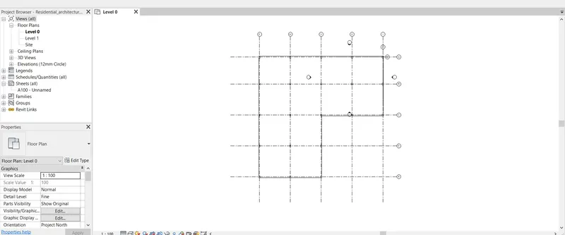
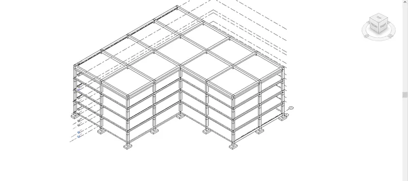
Step-2
- For creating the architectural component we have to copy the element from structural to the architectural model.
- first of all go to the given level 1
- copy the grid by copy moter.
- After this goto VG and set the some setting customs .
- And uncheck the grid option
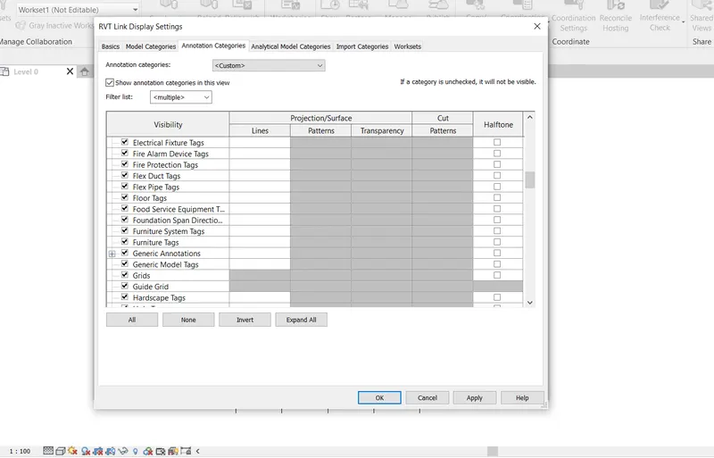
Step-3
- after this we are doing to copy the level as it is by collaborrate - copy monitor option. and press VG and remove level option.
- after this we can see the levles
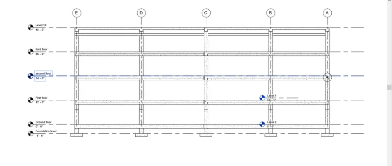
Step-4
- Now we are copying the floor to copy the floor select
- Go to north view and go to view tab choose plan view and floor plan
- select all floor and press ok
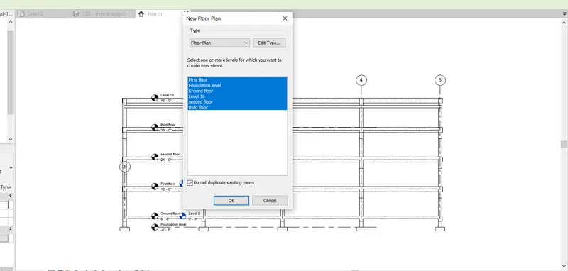
Step-5
After wthis we can see the levels in the property browser.
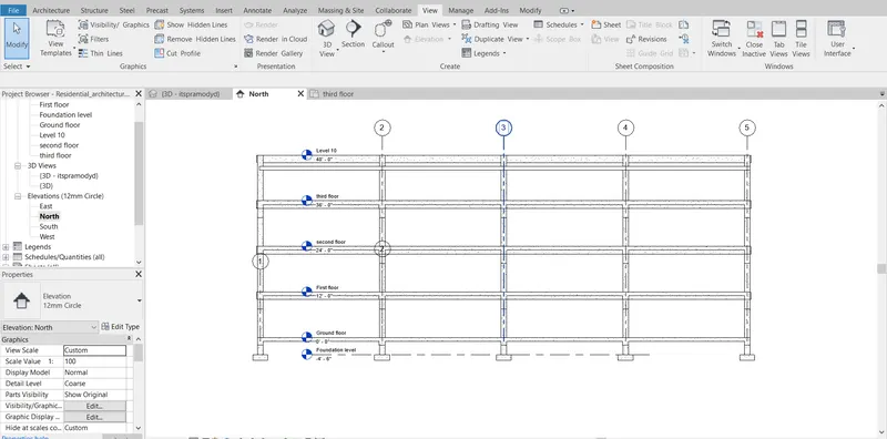
Step-6
a. Wall Layout with appropriate material and finishing
- After this we are going to putting the wall in the architectural model.
- to puttinng the wall we are going to gound floor
- and select the wall from architectural
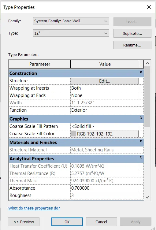
- select size 12"
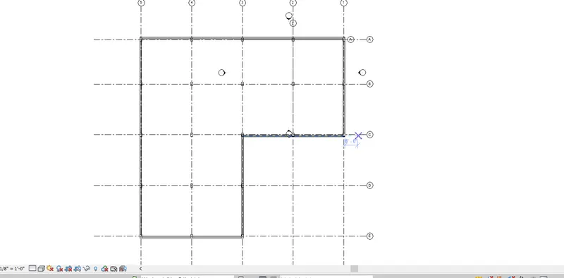
3D view:
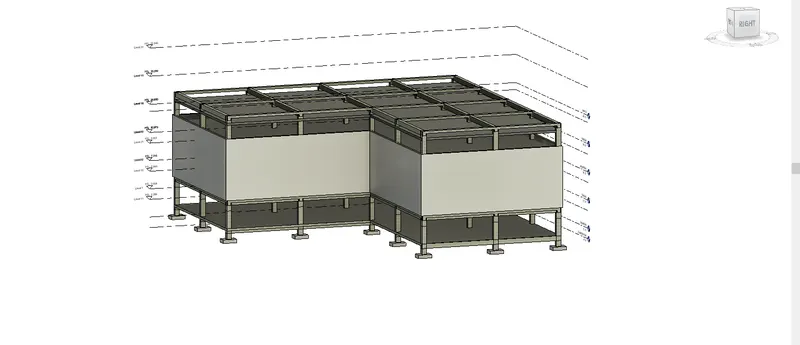
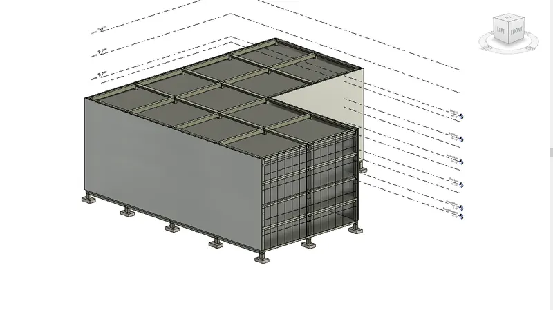
Step-7
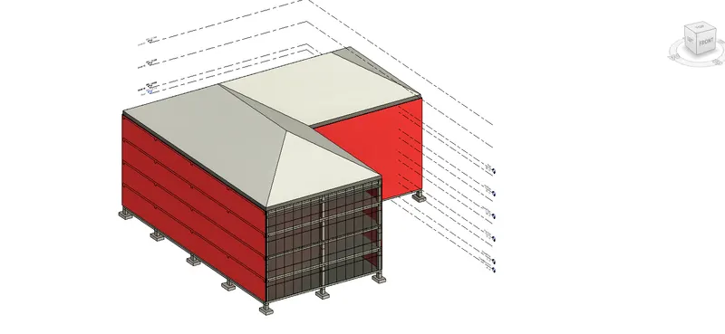
- Now we re set the size of the wall from ground floor to third floor
- select the front wall and put the curtain wall.
- Provide the material by clicking the edit type.
- and select appropriate material.
Step-8
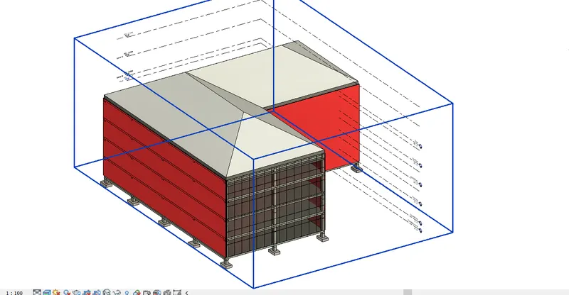
- Now we are adding the roof in the model
- to adding the roof goto the architectural tab
- select roof
- go to roof by footprint
- now draw the roof by line or pick line than finish
- provide the slop 30degreee
Step-9
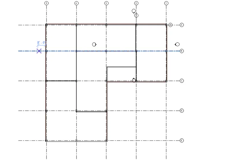
c. Interior partition walls to size rooms
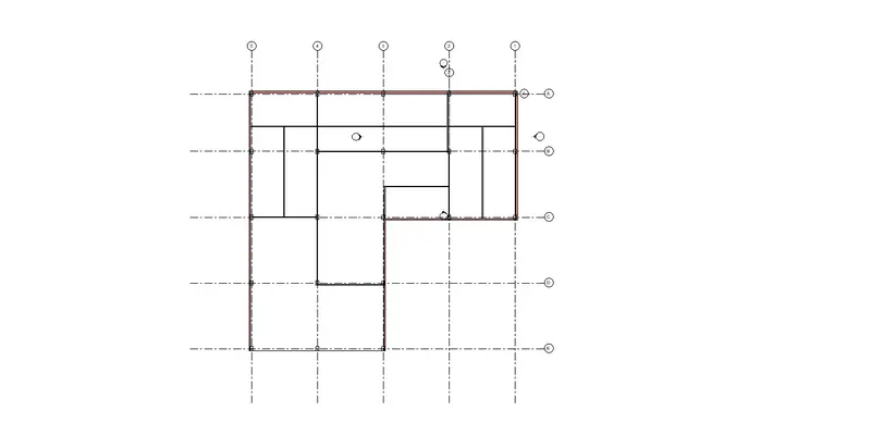
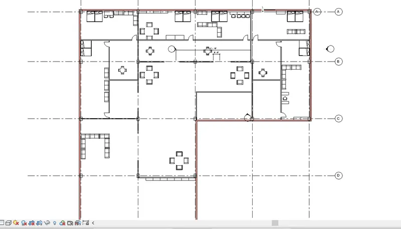
- Now we are inserting the interior wall in the model
- go to first floor and go to interior wall
- add interior wall accordinng to the room kitcheen and bedroom size.
Step-10
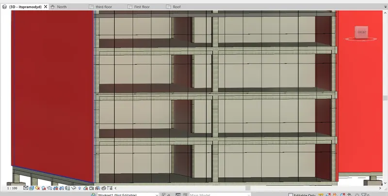
- after putting the wall in the first floor
- select all the wall and go to the edit type
- put base constituent ground floor
- and top constituent roof
- Now we are getting the internal partition wall
Step-11
d. Components to add details to a room ( Desk, Chair, Lighting, Plumbing fixtures)
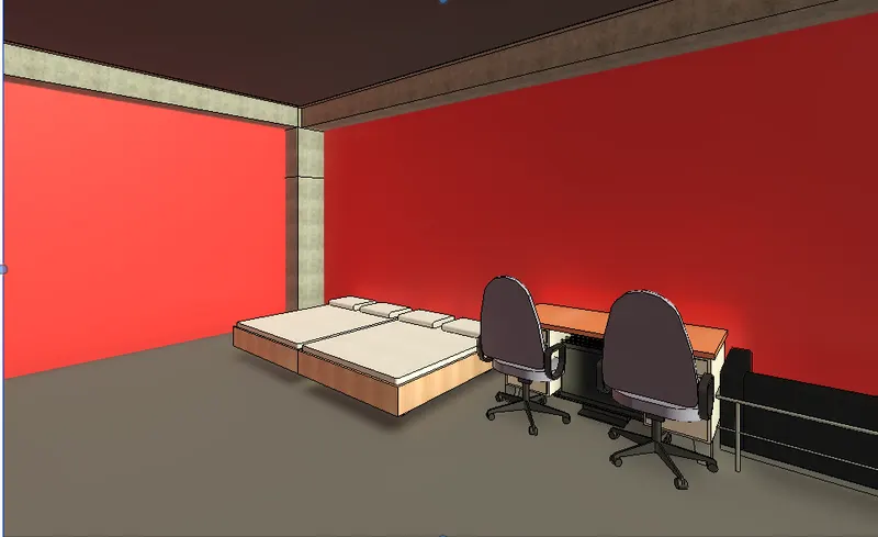
- We are start to adding the desk, chair, lighting , plumbing fixtures in the room
- with the help of architectural component we add diffrent components like bed ,chair , table ,lighting fixtures etc.to the first floor and copy the object in the same floor.
Bed Room Chair Bed And table
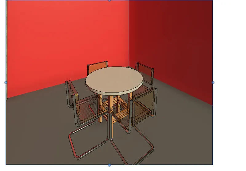
Dining Table:
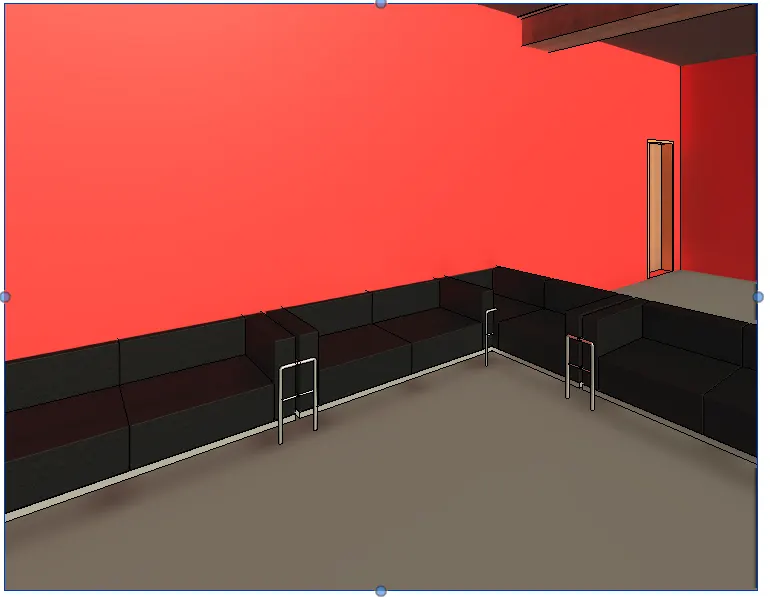
Siting Area:
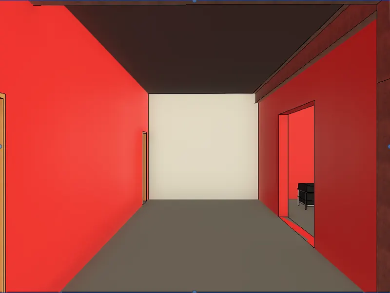
Gallery :
Step-12
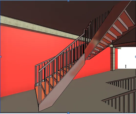
e. Add components such as stairs Elevators
- we are adding the staire with the help of architectural staire
- Add this to the first floor
- and select the component and add the staire the all the floor.
3D view:
Step-13
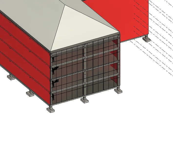
f. Have at-least one side of the building with curtain walls and glass panels
- We are provide the curtain wall at the front of the model with the help of architectural wall
Step-14
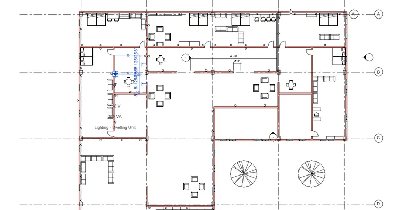
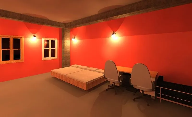
g. Include interior and exterior lighting fixtures
- Now we are tring to add the lightin fixture interior and exterior
- Goto family and us family choose interior light and place this which you want.
Step-15
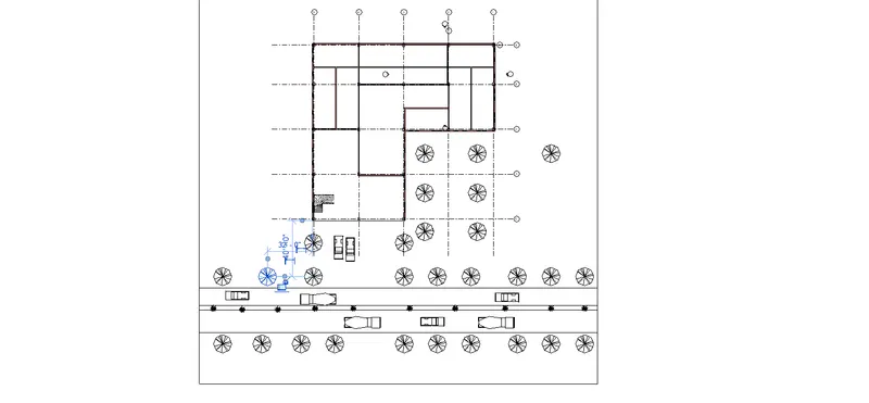
h. Place proper topographic components from outside ( Trees, Parking, Plants) to add details to the model
- With the help of topography we add topography plan in the model.
- and add Road , divider in the road , tree outside building and road
- iload vehical with the help of load family.
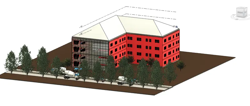
RESULT: I HAVE CRETED ALL GIVEN STRUCTURE MODEL. IN ARCHITECTURAL PLAN AND STRUCTURAL PLAN OF THE BUILDING IN THIS QUESTION WE WILL USE COLLABORATION WITH THE HELP OF REVIT SOFTWARE. AFTER GIVING THE ANSWER TO THE QUESTIONS SCREENSHOTS ARE ATTACHED WITH THE RESULTING DRAWING.
Answer to the question No.5
Question: Provide a set of drawings in an architectural and structural model to list the following details with categories and appropriate sheet templates included
a. Floor Plans with Annotations
b. Elevations
c. Sections
Answer:
Aim:Provide a set of drawings in an architectural and structural model to list the following details with categories and appropriate sheet templates included
a. Floor Plans with Annotations
b. Elevations
c. Sections
Introduction: in this question we have to create set of drawings and structural model to list the floor plans , Elevations and sections.
Procedure: TO COMPLETE THE ANSWER TO THE QUESTION WE FOLLOW THE FOLLOWING STEP:
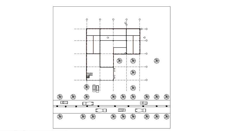
Step-1
- Open the architectural Model
- and go to the Ground floor
- Goto annotationn and provide annotations
- Take Screenshot this floor
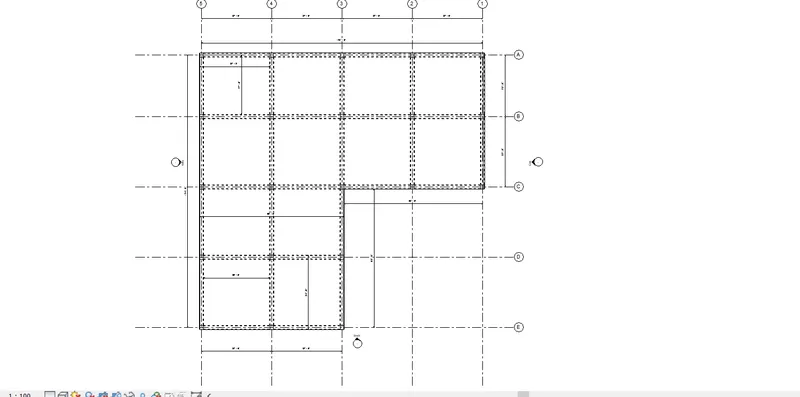
- Now go to the Third floor
- Goto annotationn and provide annotations
- Take Screenshot this floor.
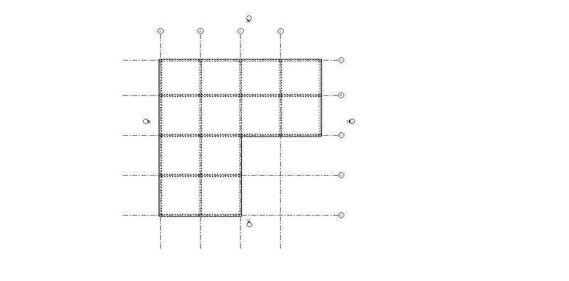
Step-2
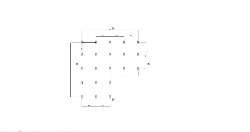
- Now go to the Foundation
- Goto annotationn and provide annotations
- Take Screenshot this floor.
Step-3
- Now go to the Second floor
- Goto annotationn and provide annotations
- Take Screenshot this floor.
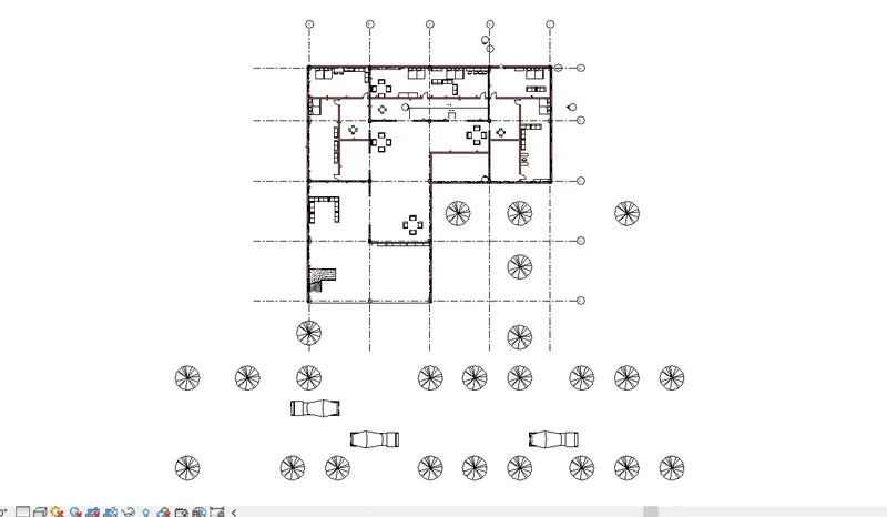
Step-4
- Now go to the First floor
- Goto annotationn and provide annotations
- Take Screenshot this floor.
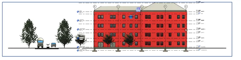
Step-5
Sections:
- Now go to the Second floor
- Goto annotationn and provide annotations
- Take Screenshot this floor.

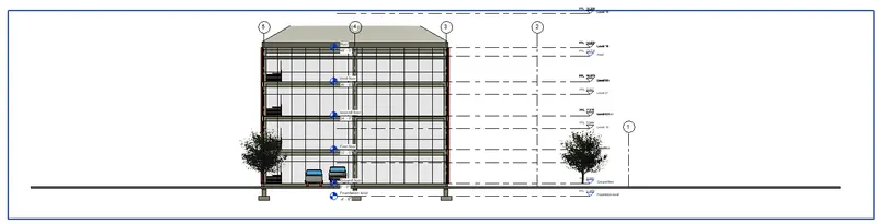
Step-6
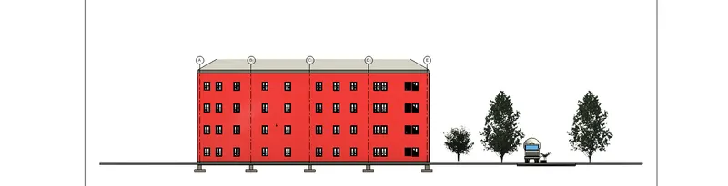
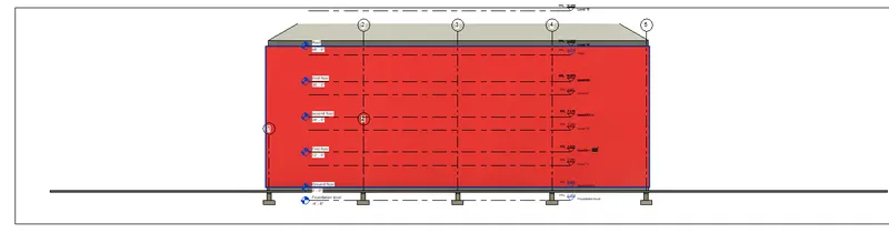
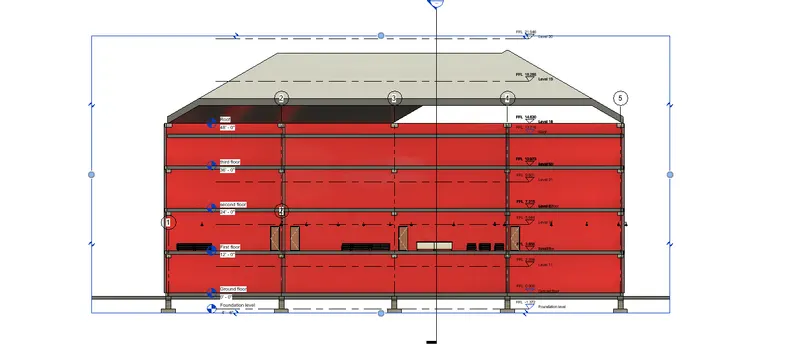
Side View:
- Now we creating the section.
- Select the floor
- For the section go to view tab
- Click section
- And provide this at the drawing
- Go to the section view.
Step-7
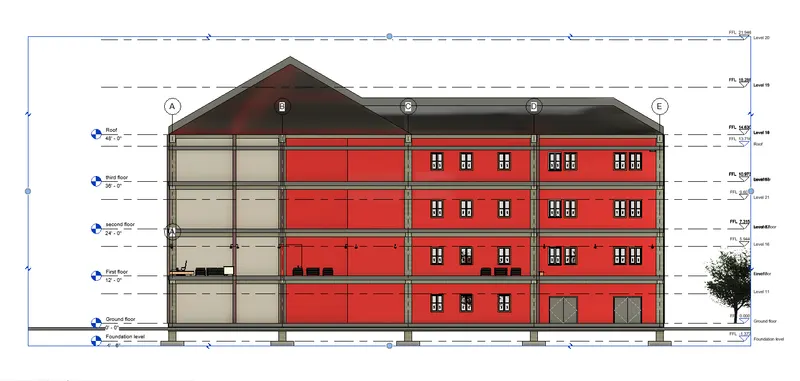
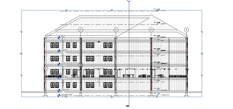
Section View:
- Now we creating the section.
- Select the floor
- For the section go to view tab
- Click section.
- And provide this at the drawing
- Go to the section view.
Step-8
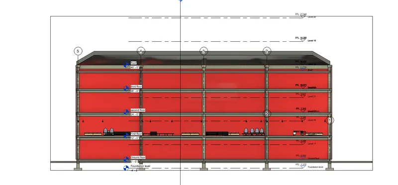
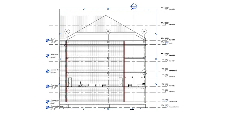
Bedroom view
- Now we creating the section of bedroom.
- Select the view
- For the section go to view tab
- Click section
- And provide this at the drawing
- Go to the section view.
- by thhis we are creating more section vertically and horizontally in the plan .
Step-9
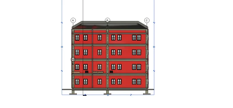
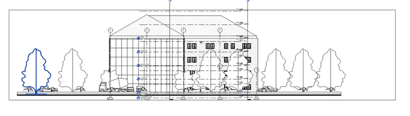
BAack view
Step-10
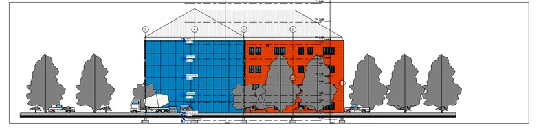
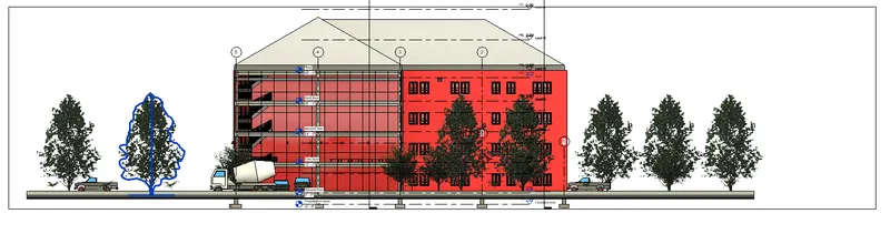
road building view
- Now we creating the views of model.
- Select the view
- For the section go to view tab
- Click section
- And provide this at the drawing
- Go to the section view.
RESULT: I HAVE CRETED ALL VIEW GIVEN STRUCTURE MODEL. WE CREATED THE FLOORS PLANS WITH ATATIONS AVATIONS AND SECTIONS.IN ARCHITECTURAL PLAN AND STRUCTURAL PLAN OF THE BUILDING IN THIS QUESTION WE WILL USE COLLABORATION WITH THE HELP OF REVIT SOFTWARE. AFTER GIVING THE ANSWER TO THE QUESTIONS SCREENSHOTS ARE ATTACHED WITH THE RESULTING DRAWING.
Answer to the question No.6
Question: Using the Rendering settings, Render images of the 3D model produced and include the rendered images to the drawing sheets.
a. Rendering from interior rooms
b. Rendering from out showing topographic features
c. Rendering through structural framing
Answer:
Aim: Using the Rendering settings, Render images of the 3D model produced and include the rendered images to the drawing sheets.
a. Rendering from interior rooms
b. Rendering from out showing topographic features
c. Rendering through structural framing
Introduction: in this question we have to creted the rendered view of the interior rooms and topographic features also rendering throght structural framing.
Procedure: TO COMPLETE THE ANSWER TO THE QUESTION WE FOLLOW THE FOLLOWING STEP:
Step-1
a. Rendering from interior rooms
- Now we are start to creating the rendering from interior side.
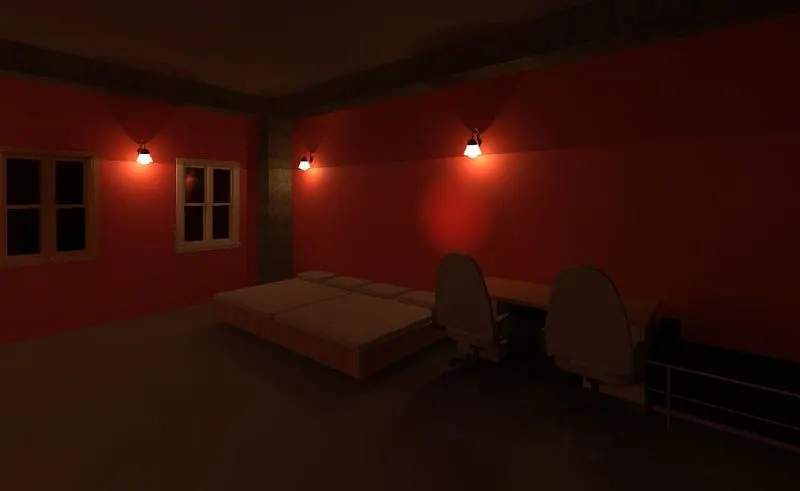
Bedroom Rendering:
Low Light Fixture:
- To render the Bedroomview of the building with model and select area by screen
- after this go to sun path on
- Now click on the rendering and set some setting
- save the picture after 100% rendering.
Light lighting Fixtures :
Step-2
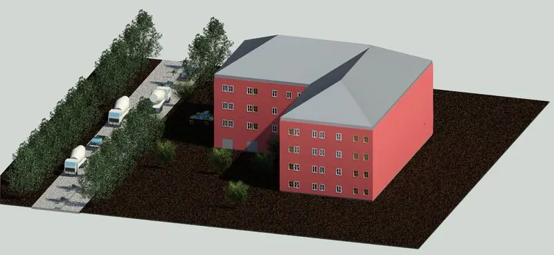
b. Rendering from out showing topographic features
- To render the topographic view of the building with model and select area by screen
- after this go to sun path on
- Now click on the rendering and set some setting
- save the picture after 100% rendering.
Side Building View:
Side Road VIew:
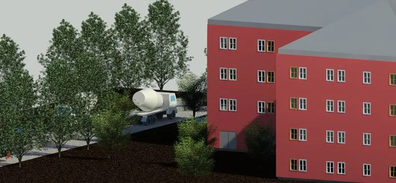
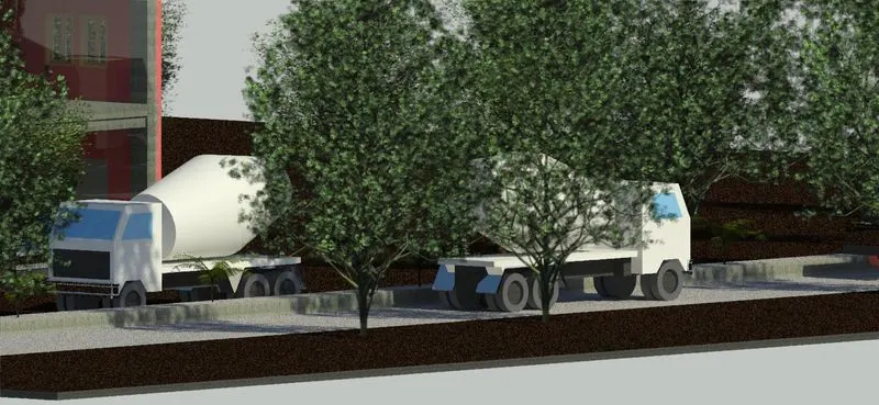
- To render the ROad view of the building with model and select area by screen
- after this go to sun path on
- Now click on the rendering and set some setting
- save the picture after 100% rendering.
Road View:
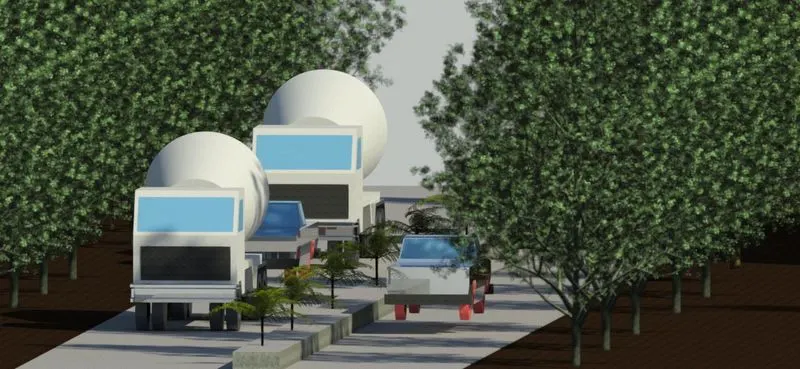
- To render the Tree and front road view view of the building with model and select area by screen
- after this go to sun path on
- Now click on the rendering and set some setting
- save the picture after 100% rendering.
Step-3
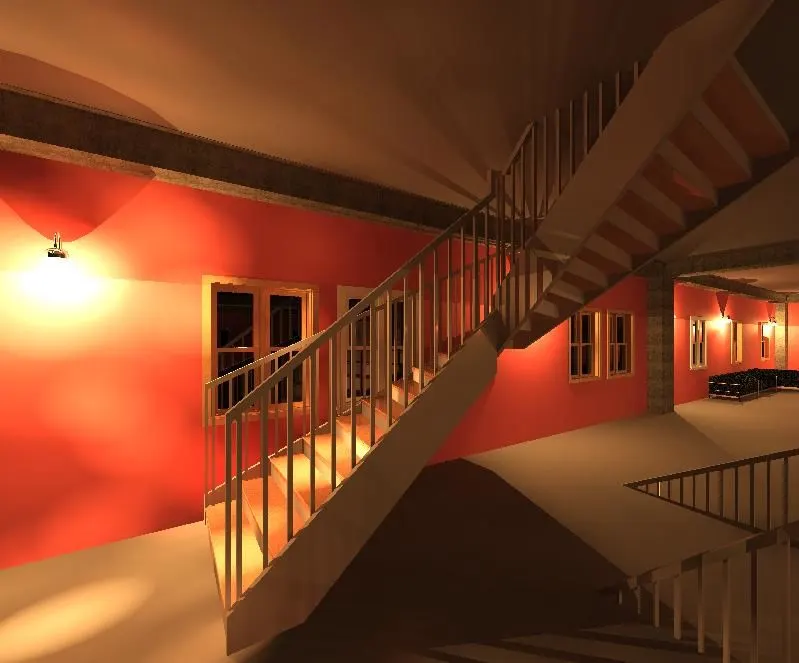
Staires:
- To render the Staire view of the building with model and select area by screen
- after this go to sun path on
- Now click on the rendering and set some setting
- save the picture after 100% rendering.
Step-4
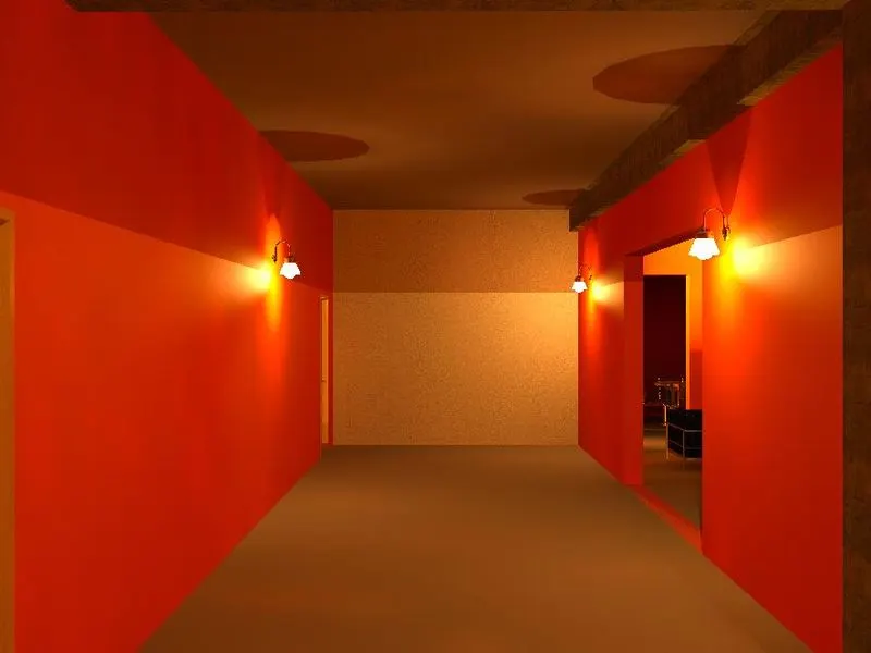
Gallary:
- To render the Gallery view of the building with model and select area by screen
- after this go to sun path on
- Now click on the rendering and set some setting
- save the picture after 100% rendering.
Step-5
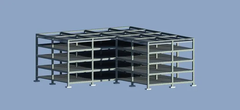
c. Rendering through structural framing
- To renderthe slab with column go to structure model and select area by screen
- after this go to sun path on
- Now click on the rendering and set some setting
- save the picture after 100% rendering.
Step-6
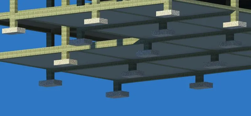
Foundation:
- To renderthe slab with Foundation model and select area by screen
- after this go to sun path on
- Now click on the rendering and set some setting
- save the picture after 100% rendering.
Step-7
Slab:
- To renderthe slab with column go to structure model and select area by screen
- after this go to sun path on
- Now click on the rendering and set some setting
- save the picture after 100% rendering.
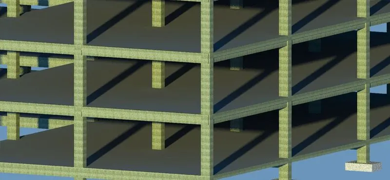
RESULT: I HAVE COMPLETED ALL THE GIVEN RENDERERED VIEW . I ADD THE LIGHTING FIXTURE AND RENDERRED THIS INTERIOR SIDE AND EXTERIOR SIDE I RENDERED THE TOPOGRAPHIC VIEW AND ALSO RENDERED THE STRUCTURE VIEW WITH THE HELP OF RENDERING OPTION.
Answer to the question No.7
Question: Print the set of drawing sheets created and submit the drawings from the architecture and structure model
Answer: TO COMPLETE THE ANSWER TO THE QUESTION WE FOLLOW THE FOLLOWING STEP:
Aim:
Introduction:
Procedure:
Step-1
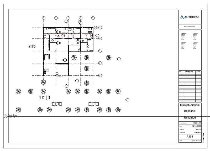
GROUND FLOOR PLAN
- To create the sheet of the drawing first open the architectural file of this model
- Go to the View tab
- After this click on the sheet option
- Select the sheet and open the A metric sheet
- Go to the view option and start to selec the view or First floor plan which we want to set the template
- Go to scale and set the drawing according to the template by scale.
Step-2
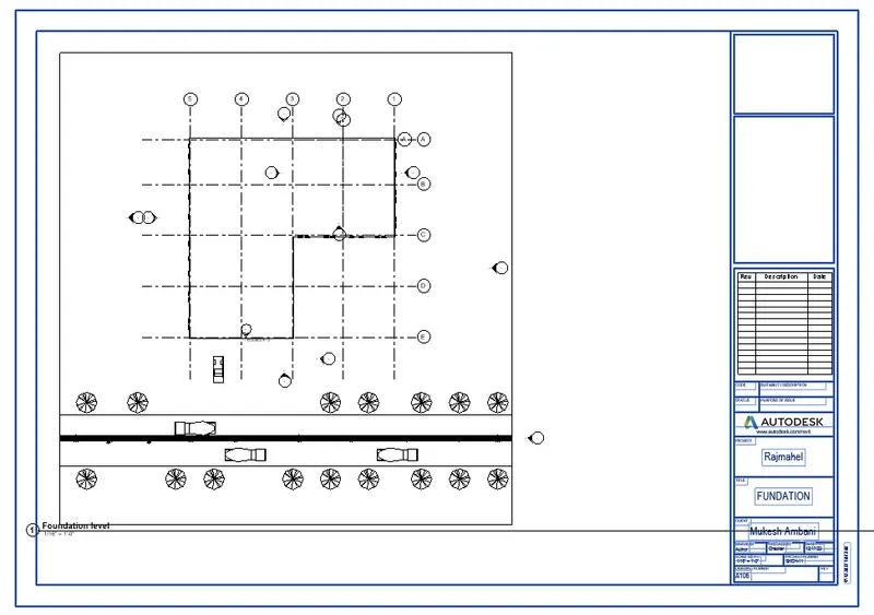
FOUNDATION PLAN
- To create the sheet of the drawing first open the architectural file of this model
- Go to the View tab
- After this click on the sheet option
- Select the sheet and open the A metric sheet
- Go to the view option and start to selec the view or Second floor plan which we want to set the template
- Go to scale and set the drawing according to the template by scale.
Step-3
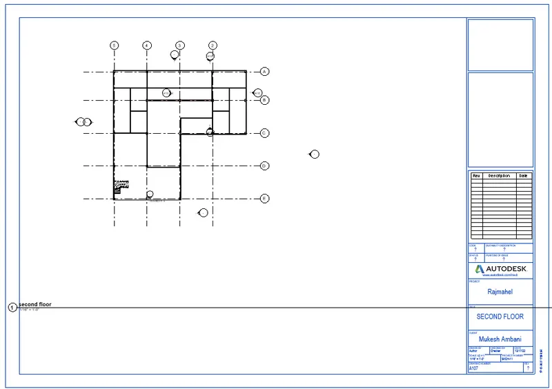
SECOND FLOOR
- To create the sheet of the drawing first open the architectural file of this model
- Go to the View tab
- After this click on the sheet option
- Select the sheet and open the A metric sheet
- Go to the view option and start to select the view or third floor plan which we want to set the template
- Go to scale and set the drawing according to the template by scale.
Step-4
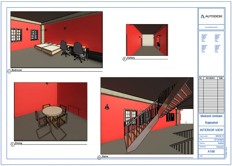
INTERIOR VIEW
- To create the sheet of the drawing first open the architectural file of this model
- Go to the View tab
- After this click on the sheet option
- Select the sheet and open the A metric sheet
- Go to the view option and start to selec the view or interior floor plan which we want to set the template
- Go to scale and set the drawing according to the template by scale.
Step-5
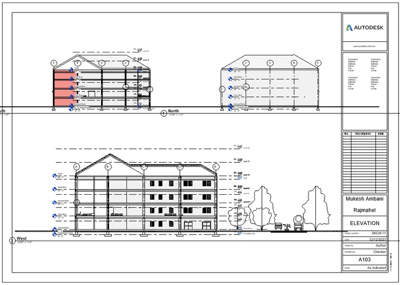
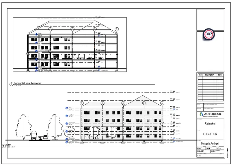
ELEVATION VIEW
- To create the sheet of the drawing first open the architectural file of this model
- Go to the View tab
- After this click on the sheet option
- Select the sheet and open the A metric sheet
- Go to the view option and start to selec the view or Elevation plan which we want to set the template
- Go to scale and set the drawing according to the template by scale.
- Download this as a PDF
Step-6
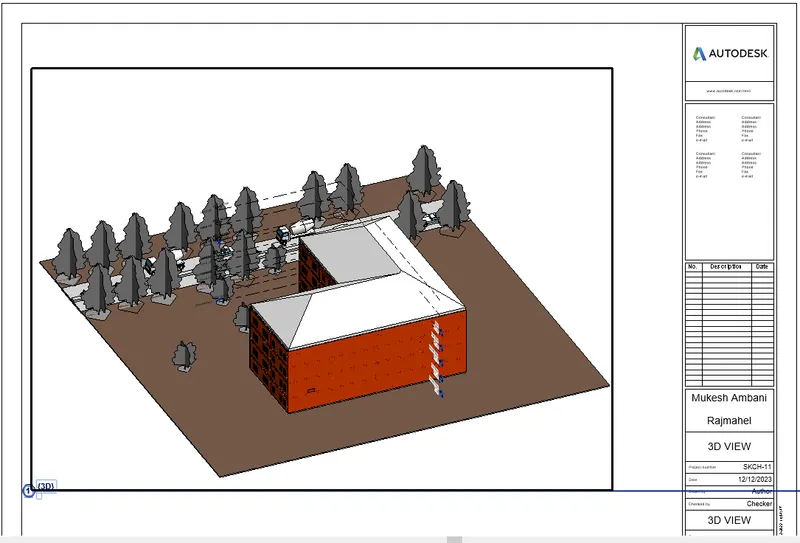
3D- VIEW
- To create the sheet of the drawing first open the architectural file of this model
- Go to the View tab
- After this click on the sheet option
- Select the sheet and open the A metric sheet
- Go to the view option and start to selec the view or 3D plan which we want to set the template
- Go to scale and set the drawing according to the template by scale.
Step-7
ROOF FLOOR PLAN
- To create the sheet of the drawing first open the architectural file of this model
- Go to the View tab
- After this click on the sheet option
- Select the sheet and open the A metric sheet
- Go to the view option and start to select the view or floor plan which we want to set the template
- Go to scale and set the drawing according to the template by scale.
- Download this as a PDF
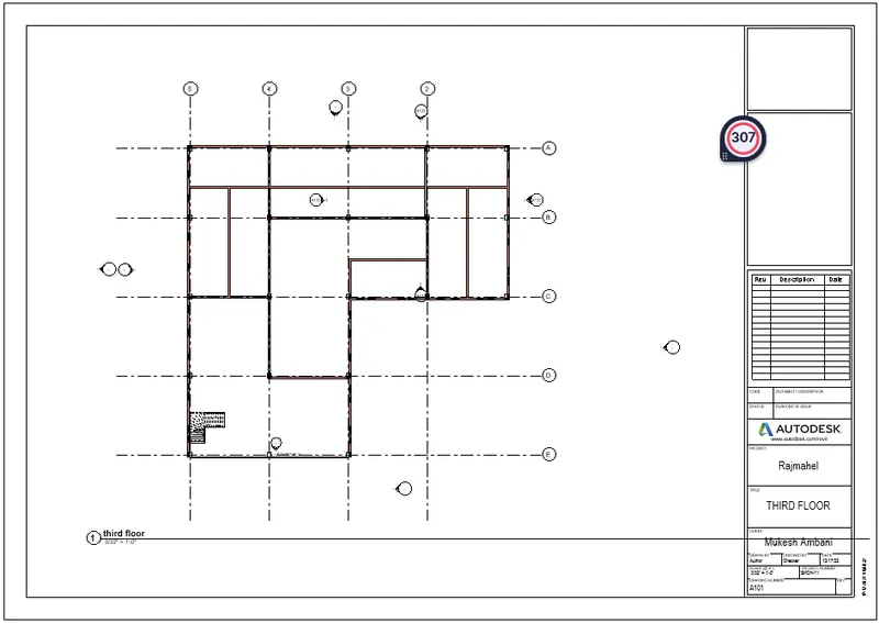
Step-8
- To create the sheet of the drawing first open the architectural file of this model
- Go to the View tab
- After this click on the sheet option
- Select the sheet and open the A metric sheet
- Go to the view option and start to select Roof plan which we want to set the template
- Go to scale and set the drawing according to the template by scale.
- Download this as a PDF
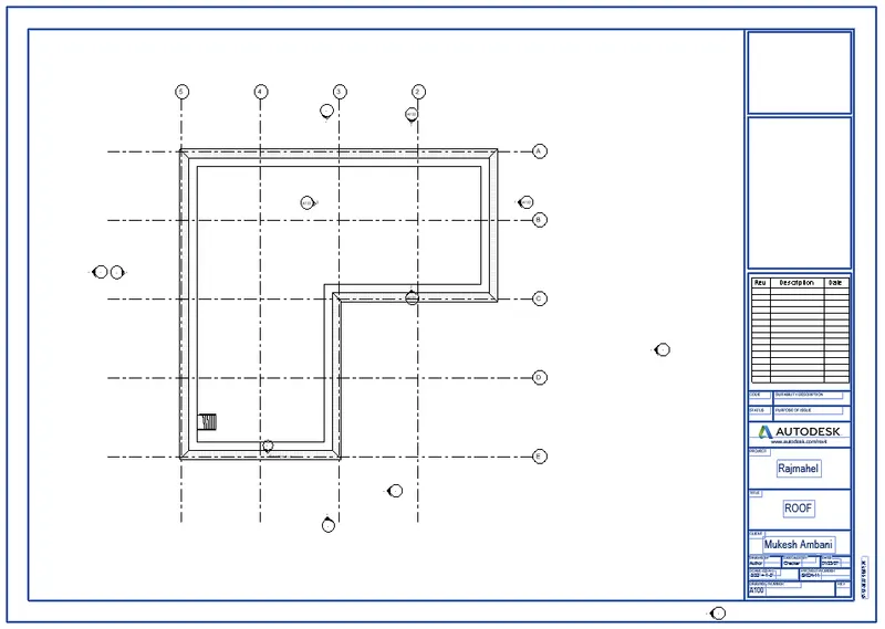
RESULT: I HAVE CREATED ALL GIVEN SEEET . IN ARCHITECTURAL PLAN AND STRUCTURAL PLAN OF THE BUILDING IN THIS QUESTION WE WILL USE VIEW TAB ANDSHEET OPTION WITH THE HELP OF REVIT SOFTWARE. AFTER GIVING THE ANSWER TO THE QUESTIONS SCREENSHOTS ARE ATTACHED WITH THE RESULTING DRAWING.