Creating Architectural and Structural model with 3D rendering using REVIT
Ans 1. I have choosen the Multi-unit Residential appartment.
Ans 2.
- My geographical location is indore as i mentioned in given revit file as well as in screenshot.
Based on assumptions and type of structure selected my modeling requirements from NBC are as follow:
- The minimum open space around a building height of 18m should be 6m (NBC Table 2,Cl. 8.2.3.1). Hence Satisfied.
- The type of Contruction i choosed here as "Type 4" construction. The FAR found for this type is 1.0 (from NBC table 3 Cl. 9.1&9.2)
- My Total Plot size is 2560.97 sq.m. and floor area is 817.70 sq.m. Therefore my FAR is found to be 0.32 that is under Type 4 i.e., 1.0. Hence Satisfied.
- In my model the width abutting the road is 12m which is above 9m. Hence Satisfied.
Ans 3.
- Aim : Using the structural model, include the following components based on the type of structure selected
a. Foundation – Isolated / Wall/Matt Foundation
b. Columns
c. Beams Connected to Columns
d. Roof Framing/ Truss
e. Floor / Decks
f. Floor Openings for Elevators and Stairs - Introduction : Creation of this particular components are to be done in Revit Structural Template by selecting different options in the given Tabs.
- Procedure :
- Foundation:
- Select Structure option in tabs.
- Then, choose type of foundation you want. (Here i choose isolated foundation).
- You can place foundations either by "At grids" or "At Columns " option. (Here i choose "At Columns" option but After placing columns which i am going to show in (b) part).
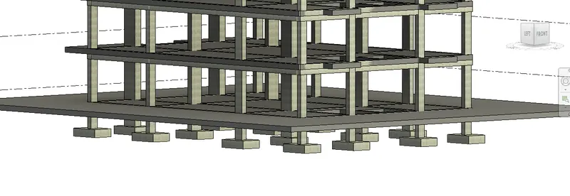
b. Columns :
- Begin with placing intersection of grids according to positioning of columns in your particular model.
- Select Structure option in tabs.
- Then, choose Column option in tab.
- There are 2 optiions for columns that is vertical or slanted. (Here i choose vertical columns).
- You can place Columns either by "At grids" or "At Columns " option. (Here i choose "At Grids" option).
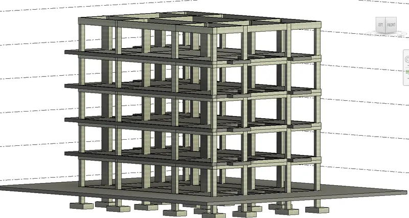
c. Beams Connected to Columns :
- Select Structure option in tabs.
- Then, choose Beam option in tab.
- Then there are so many options for placing Beams that is pick line, line, Arc etc. (Here i choose "At Grids" option).
- By selecting grids my columns are placed directly on grids particularly.
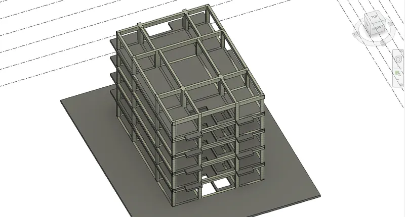
d. Roof Framing/ Truss : It has to be done in Architectural Option.
- Begin with selecting Architecture option in tabs.
- Then choose Roof option in tab.
- Then there are so many options for placing Roofs (Sloped or Plane) that is pick line, line, Arc,Rectangle etc.(Here i choose "Pick line" option).
- Then i picked lines upto where i want my roof to be placed.
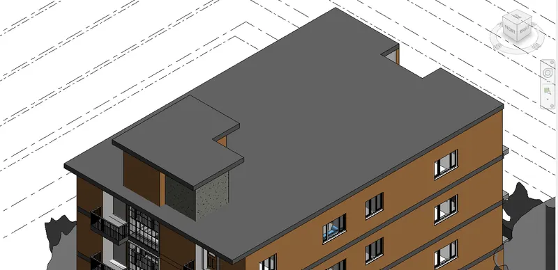
e. Floor / Decks : Here i placed Architectutal floor.
- Begin with selecting Structure option in tabs.
- Then choose Floor option in tab.
- Then there are many options for Floors Types.(Here i choose "Architectutal floor" option).
- Then there are so many options for placing Floors that is pick line, line, Arc,Rectangle etc.(Here i choose "Pick line" option).
- Then i picked lines upto where i want my Floor to be placed.
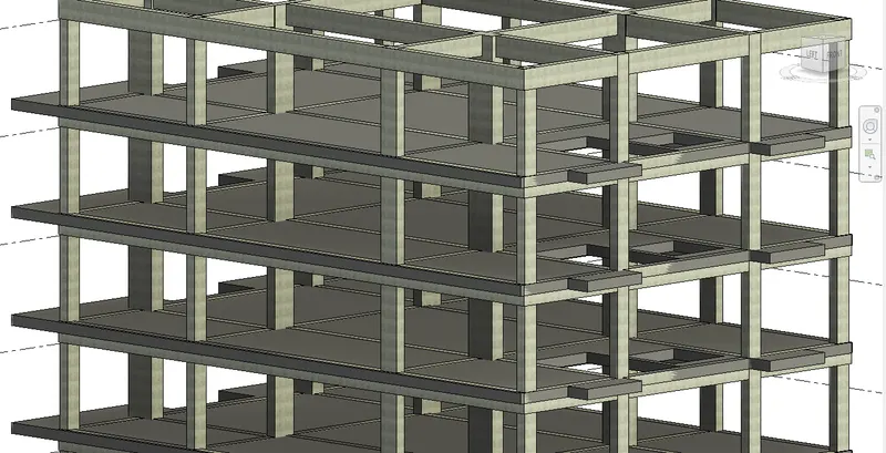
f. Floor Openings for Elevators and Stairs :
- Begin with selecting Structure option in tabs.
- Then there is an option i.e., "Shaft" choose Shaft option in tab.
- Then there are so many options for placing Shafts that is pick line, line, Arc,Rectangle etc.(Here i choose "Line" option).
- Then i make lines accordingly where i want my shaft to be placed for Openings of Elevators and Stairs.
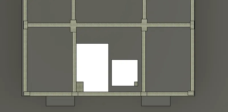
- Results : All Results are given in particular Images.
Ans 4.
- Aim : Using the architectural model, include the following components based on the type of structure selected
a. Wall Layout with appropriate material and finishing
b. Exterior façade with fancy finish
c. Interior partition walls to size rooms
d. Components to add details to a room ( Desk, Chair, Lighting, Plumbing fixtures).
e. Add components such as stairs Elevators.
f. Have at-least one side of the building with curtain walls and glass panels.
g. Include interior and exterior lighting fixtures.
h. Place proper topographic components from outside ( Trees, Parking, Plants) to add details to the model.
- Introduction : Creation of this particular components are to be done in Revit Architectural Template by selecting different options in the given Tabs.
- Procedure :
a. Wall Layout with appropriate material and finishing :
- Begin with selecting Architecture option in tabs.
- Then choose Wall option in that architectural wall in tab.
- Then choose Thickness of wall in property browser which you want to create in your model for wall layout.(Here i choose "Generic 8inch " option).
- Then there are so many options for placing Walls that is finish face exterior, finish face interior,centreline etc with different tools i.e., line,rectangle, arc etc. Choose accordingly.
- After that choose base constraint and top constraint as well as offsets accordingly.
- For Material and Finish choose wall type then go to edit type in property browser.
- Choose Structure option in that then a list appears for mterials and finish, choose accordingly in that based on your choice.
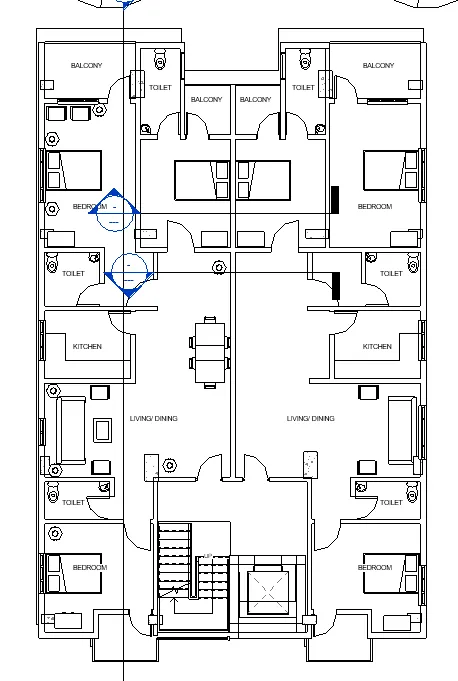
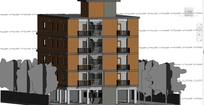
b. Exterior facade with fancy finish :
- For, exterior facade with fancy finish choose exterior components,wall elements etc.
- You can design and place windows, beam, columns, bricks,railings,glass panels etc. according to your desired planning and designing to make a good exterior facade.
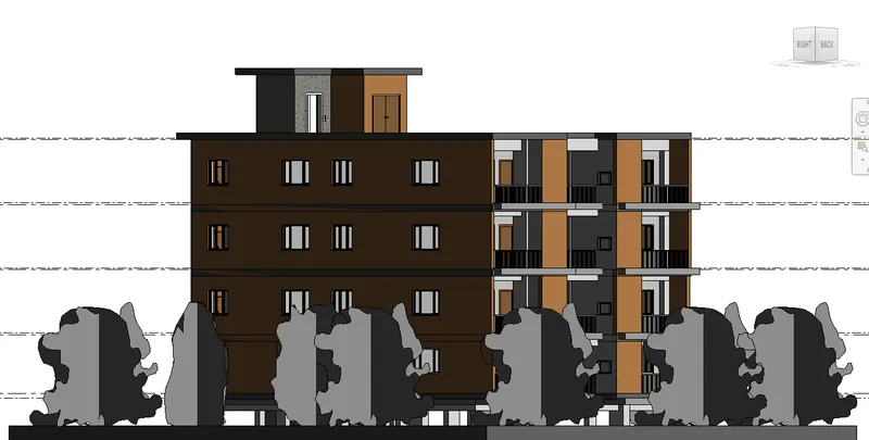
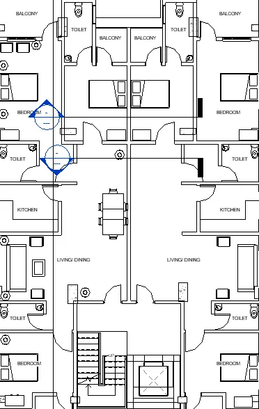
c. Interior partition walls to size rooms :
- Begin with selecting Architecture option in tabs.
- Then choose Wall option in that architectural wall in tab.
- Then choose Thickness of wall in property browser which you want to create in your model for wall layout.(Here i choose "Interior 6inch partition wall " option).
- Then there are so many options for placing Walls that is finish face exterior, finish face interior,centreline etc with different tools i.e., line,rectangle, arc etc. Choose accordingly.
- After that choose base constraint and top constraint as well as offsets accordingly.
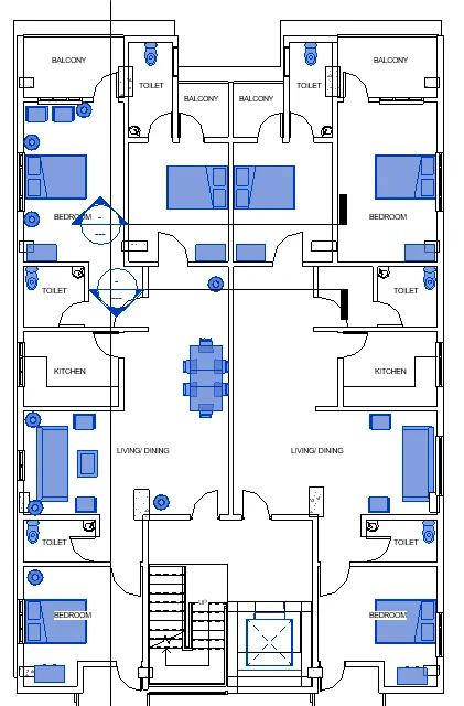
d. Components to add details to a room ( Desk, Chair, Lighting, Plumbing fixtures) :
- Begin with selecting Insert option in tabs.
- Then click on Load Family Option Choose following category,elements, instance i.e.,( Desk, Chair, Lighting, Plumbing fixtures), load it into your model.
- After loading components in your model, place different components in different rooms for various purposes.
- Can place by draging move, rotating,mirroring etc., options.
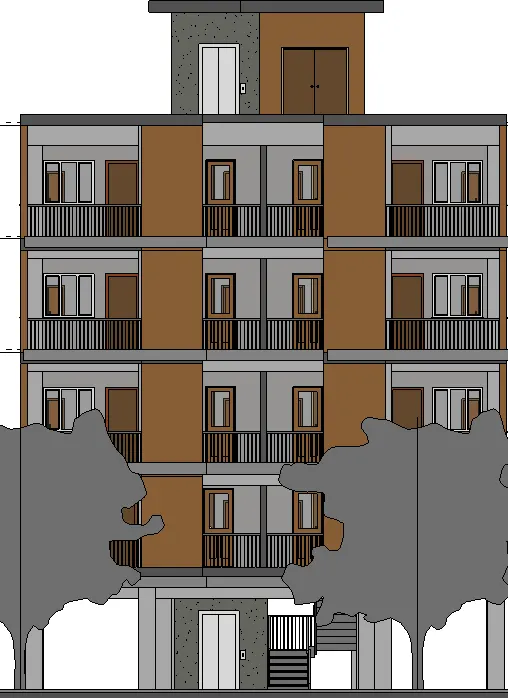
e. Add components such as Stairs , Elevators :
- For placing stairs begin with selecting Architecture option in tabs.
- Then choose Stairs option in that architectural tab.
- There you can find many options for creating stairs such as Straight,Spiral, L&U shape winder or simply run,landing etc.
- Choose your desired stairs from options and place accordingly at your desired place of strairs.
- As for Elevators begin with selecting Insert option in tabs.
- Then click on Load Family Option Choose following category,elements, instance i.e.,( Elevators).
- After loading component in your model, choose elevator and place by drag move accordingly where you define shaft opening for it.
f. Have at-least one side of the building with curtain walls and glass panels :
- For curtain wall, begin with selecting existing wall which you want to make curtain wall.
- After selecting wall, change the wall type in property browser.
- Select the wall as curtian wall and provide the grids as you want.
- Can place by draging move, rotating,mirroring etc., options at your desired place.
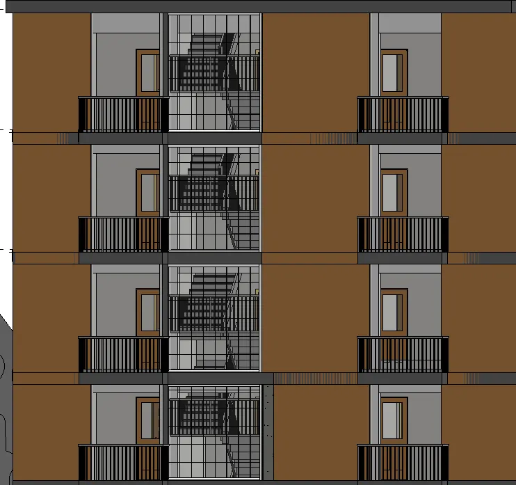
g. Include interior and exterior lighting fixtures :
- Begin with selecting Insert option in tabs.
- Then click on Load Family Option Choose following category,elements, instance i.e.,(Lighting), load it into your model.
- After loading lighting component in your model, place components in different places for various purposes.
- Can place by draging move, rotating,mirroring etc., options at your desired place.
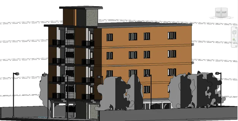
h. Place proper topographic components from outside ( Trees, Parking, Plants) to add details to the model:
- Begin with selecting Massing & Site option in tabs.
- Then click on Site Components option for trees and plants .
- Similarly ,for Parking Select Parking Component option given in the tab.
- After that a window will open in property browser in which there are plants,trees & parking component.
- Select according top your choice and place Accordingly,
- Can place by draging move, rotating,mirroring etc., options at your desired place.
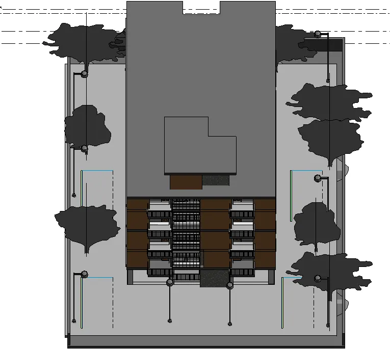
- Results : All Results are given in particular Images.
Ans 5.
- Aim : Provide a set of drawings in an architectural and structural model to list the following details with categories and appropriate sheet templates included
a. Floor Plans with Annotations
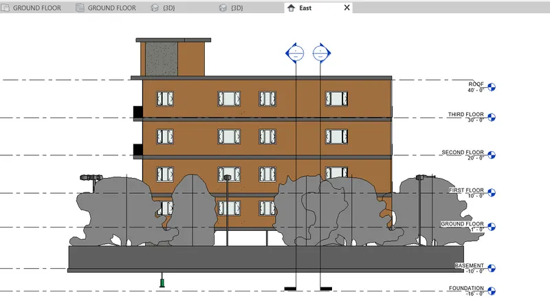
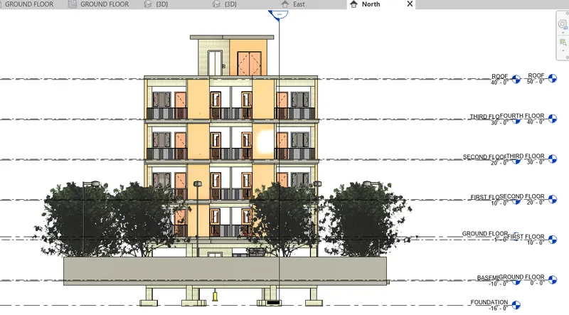
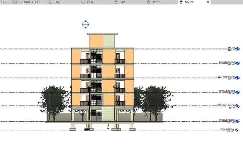
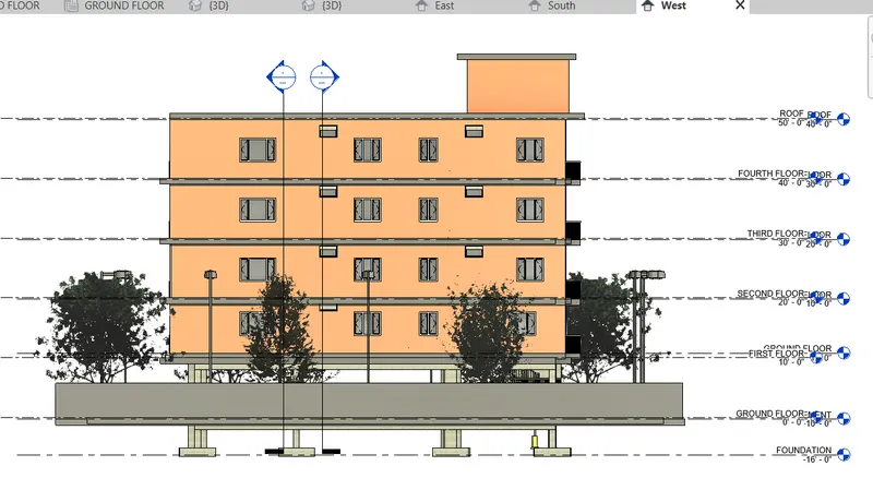
b. Elevations
c. Sections - Introduction : Creation of this particular components are to be done in Revit Architectural Template by selecting different options in the given Tabs.
- Procedure :
a. Floor Plans with Annotations :
- Begin with selecting Annotate option in tabs.
- Then click on Text option for providing Annotation text.
- In this you can edit font type, size of font etc. through property browser.
- After that type desired words which you want to annotate the particular place through text tool in the floor plans such as bedroom,kitchen,toilet etc.
- Can place by draging move, rotating,mirroring etc., options at your desired place.
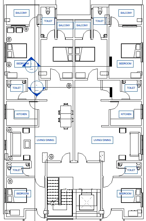
b. Elevations :
- Begin with selecting Project Browser.
- In this window you will find Elevation heading. In case if you cant able to find there go to View tab there you will see a elevation option in that ,click on that and choose elevation points accordingly wherever you want north,south,east,west for your particular project.
- After that comes on elevation in project browser in that you will find the 4 directions north,south,east,west which you had mentioned in your project.
- Click on them according to which view of the model you want to see.
- In that view you can able to see everything you had placed in that model with reference to your given Levels(floor levels,foundation etc.).
c. Sections :
- In this window you will find Section option.
- After clicking on section option, you can choose section option such as building section or wall sectiion etc.
- After choosing option, it allows you to make section line to cut section according to your view.
- You can do it by just click and drag from where to where you want section of structure.
- After that you can find your view in project browser window explained similarly in Elevtaion (point no. 3).
- Click on particular section name according to which view of the model section you want to see.
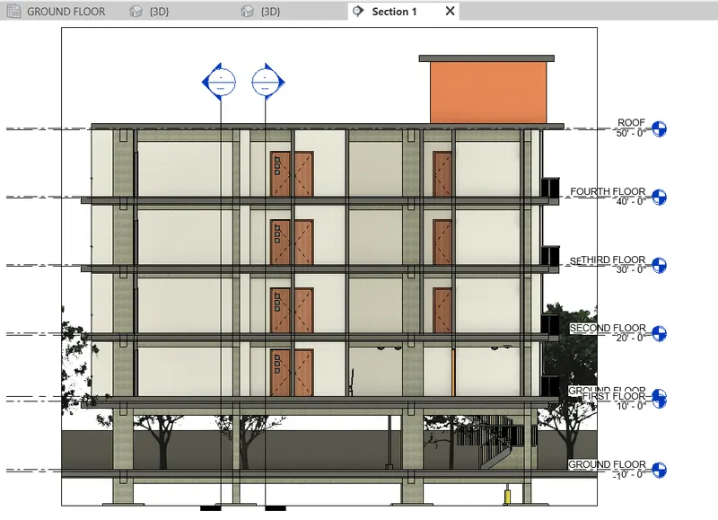
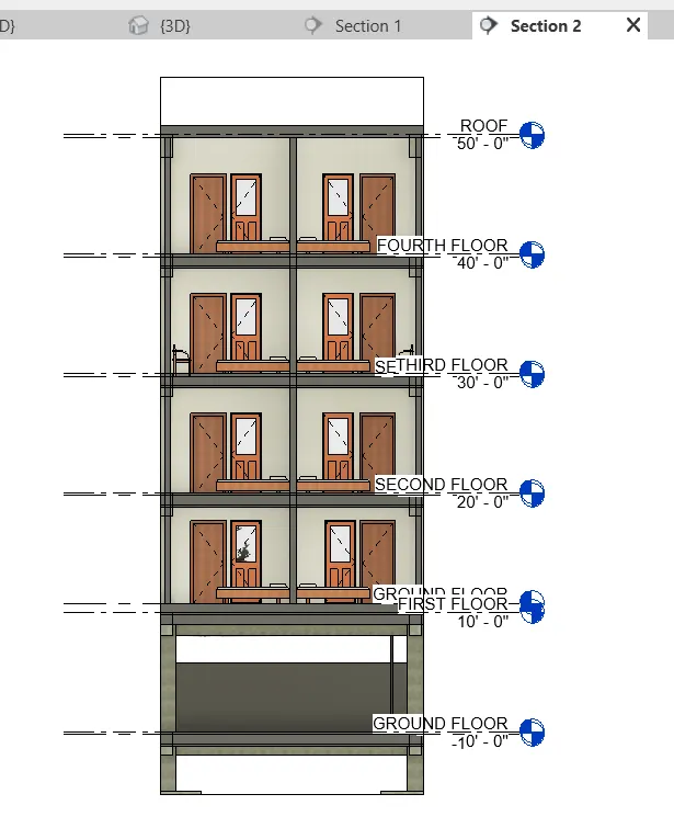
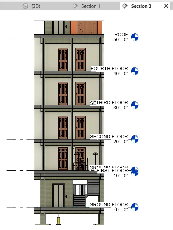
- Results : All Results are given in particular Images.
Ans 6.
- Aim : Using the Rendering settings, Render images of the 3D model produced and include the rendered images to the drawing sheets
a. Rendering from interior rooms
b. Rendering from out showing topographic features
c. Rendering through structural framing - Introduction : Creation of this particular components are to be done in either Revit Architectural or Structural Template by selecting 3D Camera and Rendering options in the given Tabs.
- Procedure :
a. Rendering from interior rooms :
- Begin with selecting 3D tool in Tabs.
- After clicking on 3D option, there you can choose Camera option.
- After that you will find a camera icon on your plan, you can place that icon according to your desired views which you want.
- Then you will find your particular view in project browser 3D view option, you can also rename it according to your annotation.
- Finally, you can resize your views on particular window and make it ready for Rendering process.
- You can render you views by choosing view tab there you can render option of simply just click "RR" i.e., shortcut key to open the render window.
- In render window you can adjust rendering settings according to your choice.
- Finally click on Render option to start process after that you can save it in your project by your desired name.
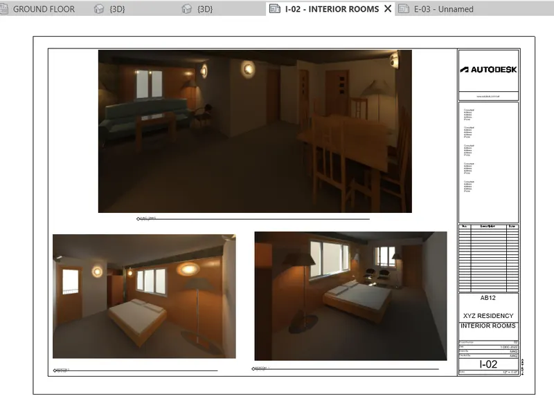
b. Rendering from out showing topographic features : Similarly to the procedure of Ans 6a.
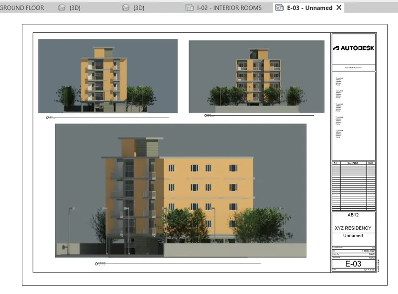
c. Rendering through structural framing : Similarly to the procedure of Ans 6a.
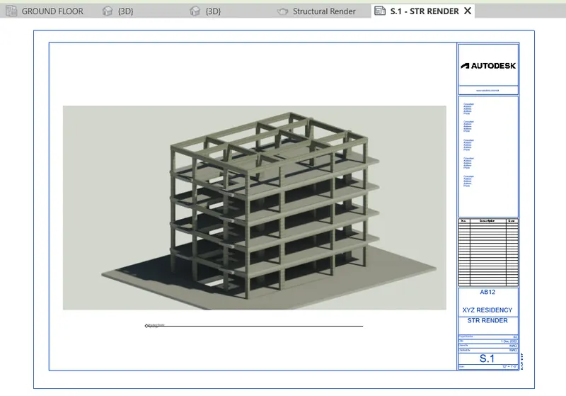
- Results : All Results are given in particular Images.
Ans 7.
- Aim : Print the set of drawing sheets created and submit the drawings from the architecture and structure model.
- Introduction : Printing of particular sheets has to done in Print window given Autodesk Revit Software.
- Procedure :
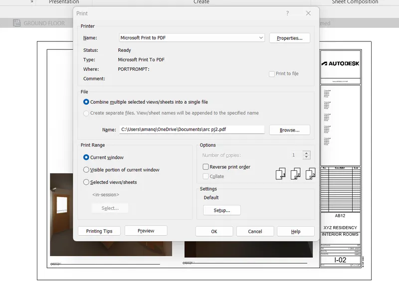
- Print option can be accessed from File menu or simply by clicking CTRL+P(shortcut key) to open print window.
- There you can see many editing options for printing such as-
- Printer- To select Printer, if you multiple printers connected to your device then you can choose from which printer you want to print. You can also change option from Print to Fax,pdf etc.
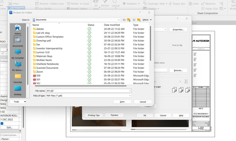
- File- In this you can select or browse the folder in your device for storage of particular Revit file.
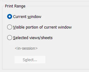
- Print range- In this, the selection of print view has to be done by options such as current window,selected views/sheets,visible portion.
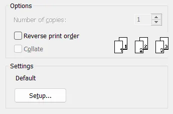
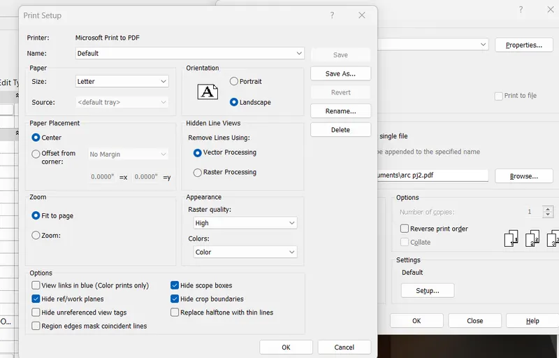
3. There are some more options like number of copies and page setup such as page size,orientation etc.
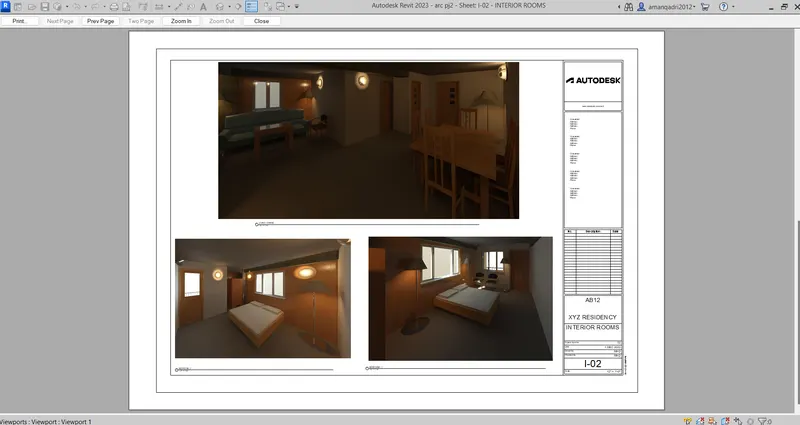
4. After editing of print options you can see the final preview of print which you want by preview option at bottom of window.
5. Then after finalizing the preview you can make Print of that particular view by clicking OK.
6. Save it in your desired space of device.
- Results : All Results are given in particular Images.
...........THANKYOU.............