Creating Architectural and Structural model with 3D rendering using REVIT
1. Select the type of structure you want to build from one of the three below
Multi unit Residential Apartment
Office Buildings
School
ANSWER
I want to select the model of Multi unit Residential Apartment.
Residential Apartments
- It is a housing unit which includes a kitchen, bathroom, bedroom and living room.
- It occupies only a part of building.
- They may be owned by an owner-occupier or can be rented by tenants.
2.Assume reasonable assumptions for geographic and location details for your project modeling. Based on assumptions and type of structure selected identify the modeling requirements from NBC.
ANSWER
- My assumed location details of Multi unit Residential Apartments are Ambattur, Chennai-600053.
- If I draw the multi residential apartments of modeling gives the model requirements from NBC of all categories.
3. Using the structural model, include the following components based on the type of structure selected
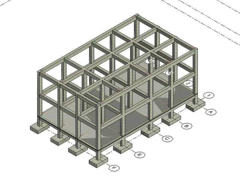
Foundation – isolated / wall/ mat foundation
Columns
Beam connected to columns
Roof Farming/Truss
Floor/ Decks
Floor openings for elevators and stairs
AIM
To create foundation, columns, beams, roof farming, floor, floor openings for elevators and stairs by using Revit Software.
INTRODUCTION OF STRUCTURAL MODEL
- Structural models helps to engineers make an accurate estimation of the materials and components used during construction.
- Its also aids in getting a clear perception of both interior and exterior 3d views.
- It contains a main elements of foundation, column, beam, roof, floor, wall..,
PROEDURE
- Open the structural diagram which created before.
Foundation
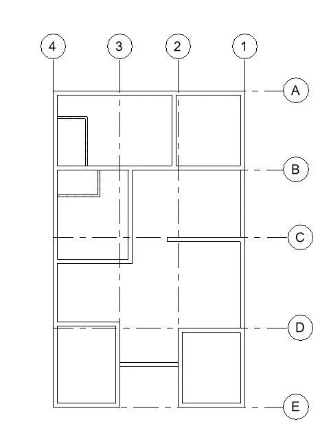
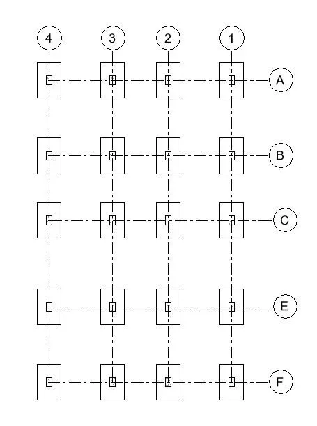
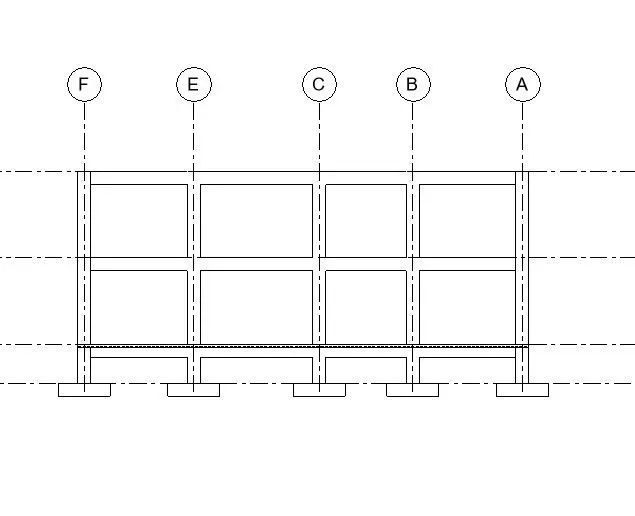
- Before we create the foundation , to draw the grids for longitudinal and transverse plan.
- Then, to draw the levels of foundation below the ground floor level at -4’6”.
- Go to Structural Tab > foundation tab, here I choose to Isolated footing at the level of Foundation.
- After that, Go to insert > Load families to load the footing design from structural foundations.
Columns
- The same procedure for Columns located.
- Here also, we changed the dimension of column from properties.
Beams
- The same procedure to creation of beam at constraint level and then each and every beam have been connected to the columns by structural farming.
TRUSS
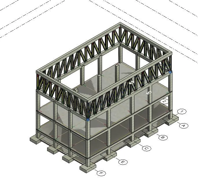
- To create a truss of standard designed requirements.
- Go to structural tab > click on truss > select the truss model and place where we require at desired locations.
Floor
- The same procedure for the above truss formation.
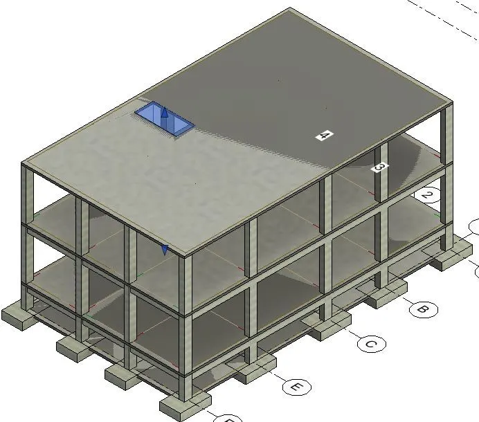
- Go to structural tab > click on floor > create the boundary line and then to click ok.
- Finally to getting the floor with desired thickness and align the associated location.
Floor openings of elevators and stairs.
- To create the opening for stairs to usage of floor to floor movement without any disturbance.
- Go to structural > shafts > create the opening of boundary and then click ok to get the openings with a selected constrain level.
4. Using the architectural model , include the following components based on the type of structural selected
Wall layout with appropriate material and finishing
Interior partition wall to Size Rooms
Components to add details to Room ( Desk, chair, table, lighting, plumbing fixtures )
Add components such as stairs elevators
Have at-least one side of building with curtain walls and glass panels
Include interior and exterior lighting fixtures
Place proper topographic components from outside ( Trees, parking, plants) to add details to the model
AIM
To create architectural plan and to add the components based on the type of structure selected.
PROCEDURE
- To create an architectural model of residential unit.
- Go to architecture tab > load families > load all components to select depends upon the different structure area of rooms or outside.
RESULTS
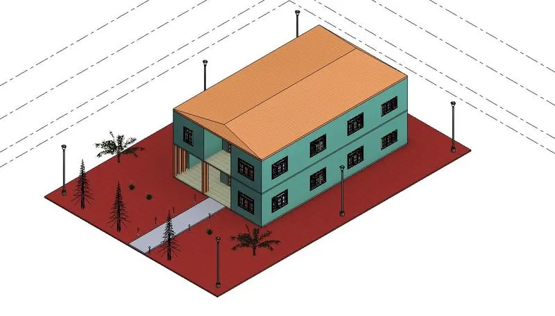
Wall layout
- To drawn the wall, then to select the wall to change the appropriate material, finishing and thickness.
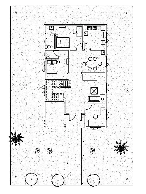
Interior partition wall
- Interior partition wall are thickness of 4”and to add appropriate material.
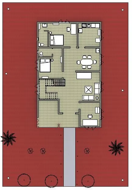
Components to add each room
- The components of each and every room to added. ( desk, table, lighting, bed, table, sink, shelf, stoves, plumbing fixtures, chair, etc..,)
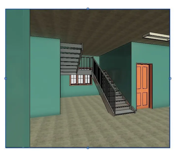
Add components such as stairs
- To add the components of materials in stair with railing.
Curtain and Glass panel
- To created the wall should be in curtain.
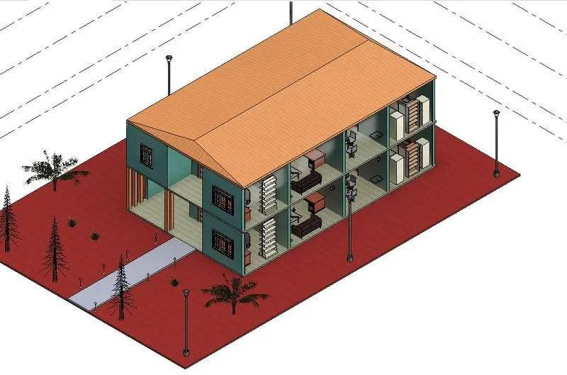
Lighting fixtures
- The lighting fixtures of interior and exterior are added.
Topography components
- To add the topography components of tress, plants, lighting is done.
5. Provide set of drawings in architectural and structural model to list the following details with categories and appropriate sheet templates include
Floor plan with annotations
Elevation
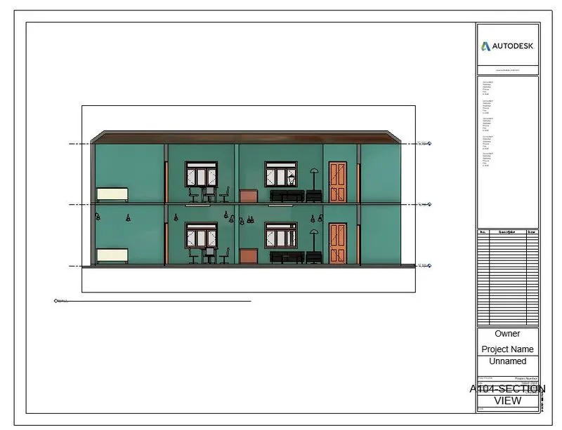
Section
AIM
To provide the set of drawing in architectural and structural model to the list of following with categories and appropriate sheet templates.
PROCEDURE
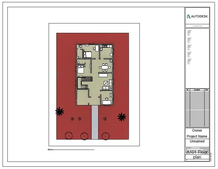
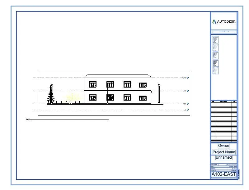
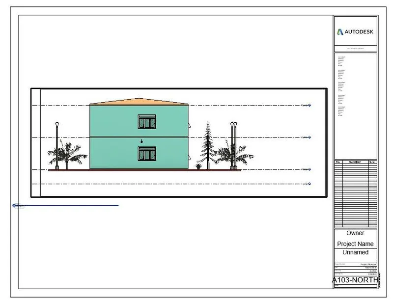
- To open the architectural and structural plan, and to prepared the box of all categories of plan views to add the sheet template.
- The sheet templates are created by floor plan, elevation and sectional view of diagrams.
RESULTS
Floor plan view with sheet template
Elevation view with sheet template
Sectional view with sheet template
6. Using the Rendering setting, Render image of 3D model produced and include the Render image to the drawing sheet.
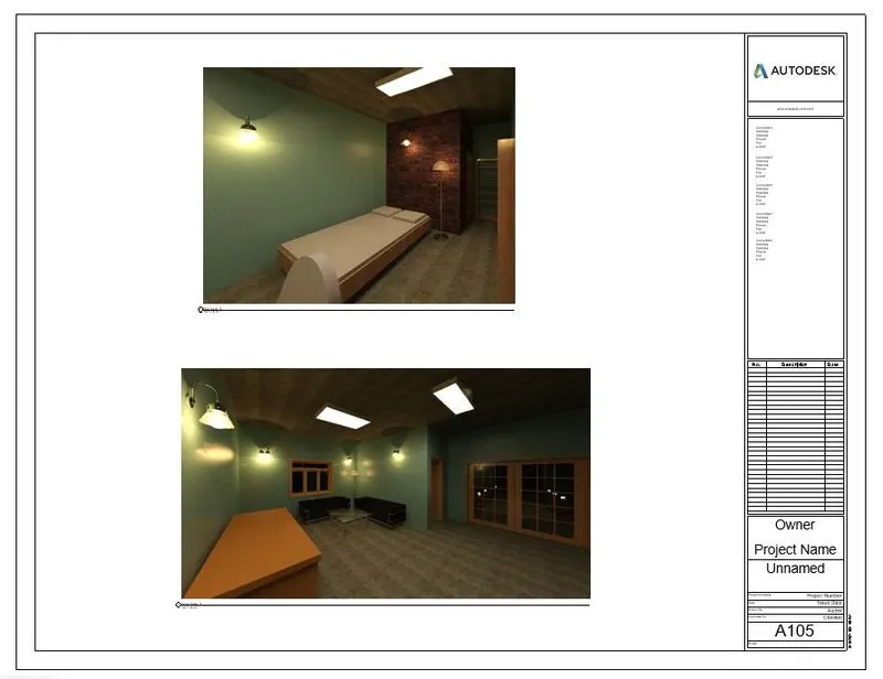
Rendering from interior Rooms
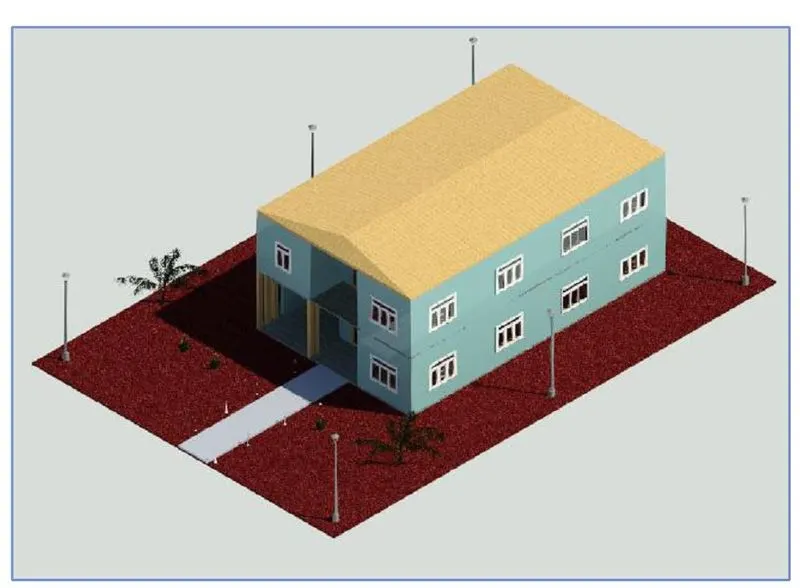
Rendering from out showing topography features
Rendering through structural farming
AIM
To use the Rendering settings of drawing and to add the image to sheet templates.
PROCEDURE
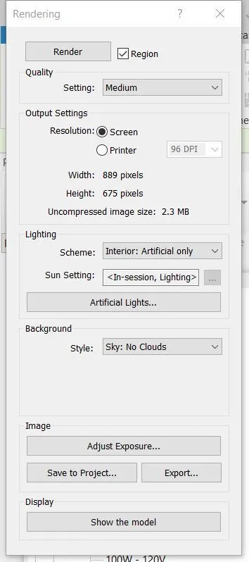
- Go to view tab > to select the Render options.
- After that to create a region and modify the sun setting of exposure based conditions, then to click ok, rendering images are created.( to keep interior for sun and artificial )
RESULTS
Exterior Rendering images
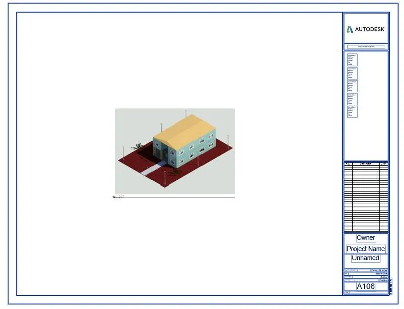
Interior Rendering images with Rooms
7. Print the set of drawing sheets created and submit the drawings from architectural and structural model.
AIM
To print the set of projects of drawing sheet created.
PROCEDURE
- After completion the whole work of our drawings.
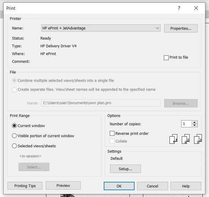
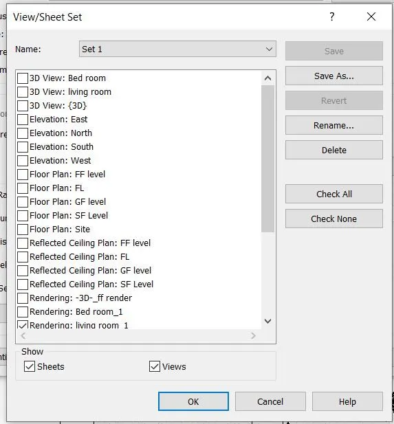
- Go to file tab > select print options to taken the copy with in our hand to execute the next step.
RESULTS