Creating Architectural and Structural model with 3D rendering using REVIT
1Q:Select the type of structure you want to build from one of the three below:
a. Multi-Unit Residential Apartment
b. Office Buildings
c. School
ANS: Multi-unit residential apartment
2Q: Assume reasonable assumptions for geographic and location details for your project modeling. Based on assumptions and type of structure selected identify the modeling requirements from NBC.
ANS:
My building is constructed in the residential area
My building is constructed in the plain area (geographic)
As per the NBC, the height limit will be given in NBC part V-1. (National building code)
The open space around the building shall not be less than 4.5m
The type of construction as type 2 construction, the FAR value for the business building shall be taken as 2.9.
The plot size is taken as 14.6mx23.6m and individual floor area is 10m2. Hence, FAR value obtained is 2.14 which is within the prescribed limits as per NBC.
The width of the road abutting the building is taken as 9m (30').
3Q:
Using the structural model, include the following components based on the type of structure selected
a. Foundation – Isolated / Wall/Matt Foundation
b. Columns
c. Beams Connected to Columns
d. Roof Framing/ Truss
e. Floor / Decks
f. Floor Openings for Elevators and Stairs
PROCEDURE:
Open the structural model, collabrate it with the central, and save it.
Now using the grid create it horizontal and vertical direction and specify the location to the grids.
Create the levels in the elevation.
Now in the stuctural tab select the isolated foundation and select in the grids in foundation level.
In the architecture tab select the type of colum and dimensions of colum, select at the grids and give the height of 10'.
To connect the beam to column select the stutural tab and click on the beam and select the beam type and edit the dimensions and connect the beam to column.
To create the floor go to the architecture tab and select the floor and floor type create.
Now create the stairs in architecture tab and select option stair, and model the stairs to the selected level.
And using the shaft option in architecture tab create the shaft for the floor opening for the stairs.
4Q: Using the architectural model, include the following components based on the type of structure selected
a. Wall Layout with appropriate material and finishing
b. Exterior façade with fancy finish
c. Interior partition walls to size rooms
d. Components to add details to a room ( Desk, Chair, Lighting, Plumbing fixtures)
e. Add components such as stairs Elevators
f. Have at-least one side of the building with curtain walls and glass panels
g. Include interior and exterior lighting fixtures
h. Place proper topographic components from outside ( Trees, Parking, Plants) to add details to the model
PROCEDURE:
Open the architectural model, collabrate it with the central, and save it.
Now using the grid create it horizontal and vertical direction and specify the location to the grids.
Create the levels in the elevation.
Now insert the stuctural file in the architectural model.
Select the wall in architectural tab and type of wall and height.
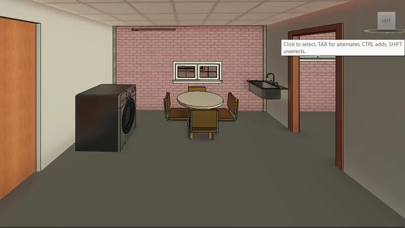
Also model the interior portion walls of the room.
Using the component option add the material in the model doors,windows,etc.,
5Q:Provide a set of drawings in an architectural and structural model to list the following details with categories and appropriate sheet templates included
a. Floor Plans with Annotations
b. Elevations
c. Sections
PROCEDURE:
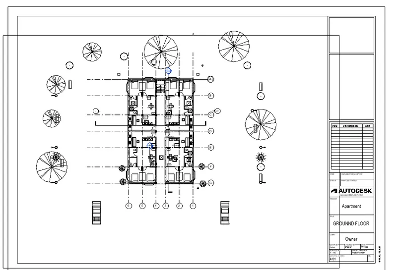
To create the floor plan with the sheet we need to create the sheet na dinsert the floor paln in the sheet.
Give the information in the sheet.
Ground floor plan with sheet.
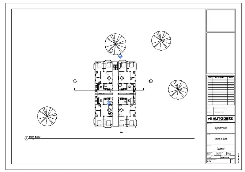
Third floor plan with sheet.
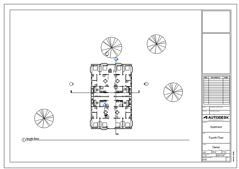
Fourth floor plan with sheet.
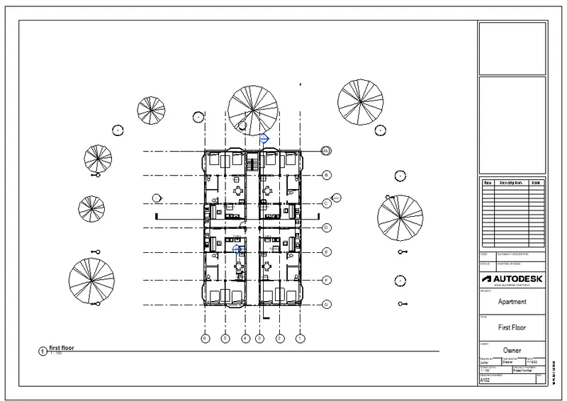
Floor plan with the sheet.
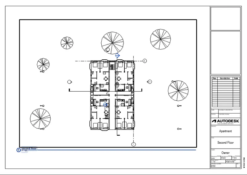
Second floor with the sheet.
Elevation east-west with sheet
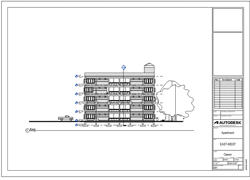
Elevation north-south with sheet
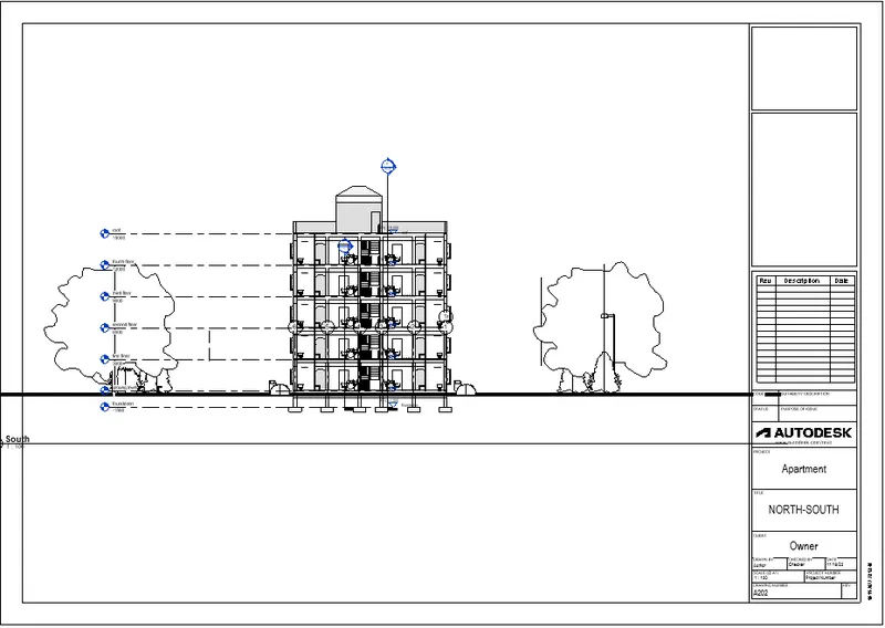
Section A with the sheet.
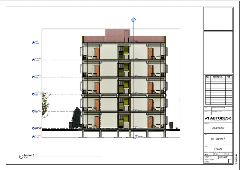
Section B with the sheet.
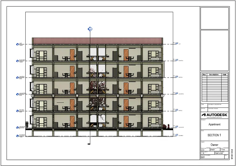
6Q:Using the Rendering settings, Render images of the 3D model produced and include the rendered images to the drawing sheets
a. Rendering from interior rooms
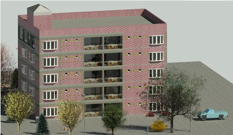
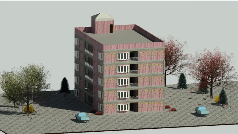
b. Rendering from out showing topographic features
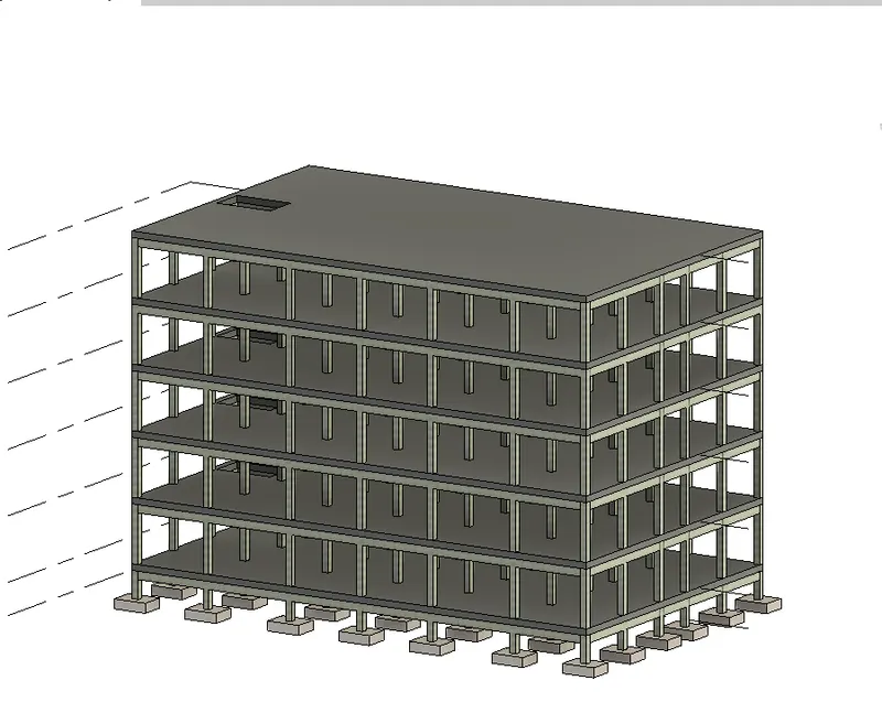
c. Rendering through structural framing
PROCEDURE:
TO create the render images we need to select the camera place it at a point.
Now in the View tab select the render option and render the image.
Master Bedroom rendering image.
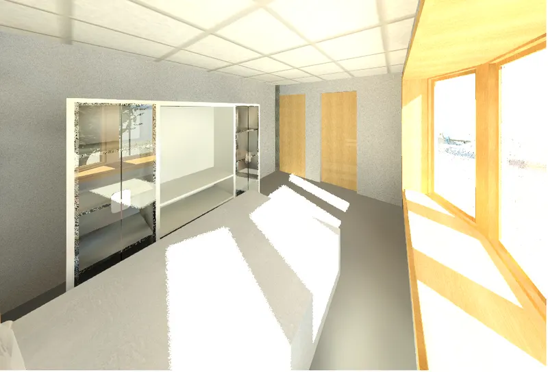
Bed room 1
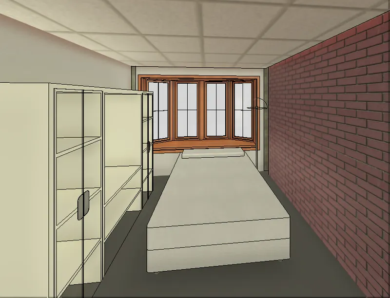
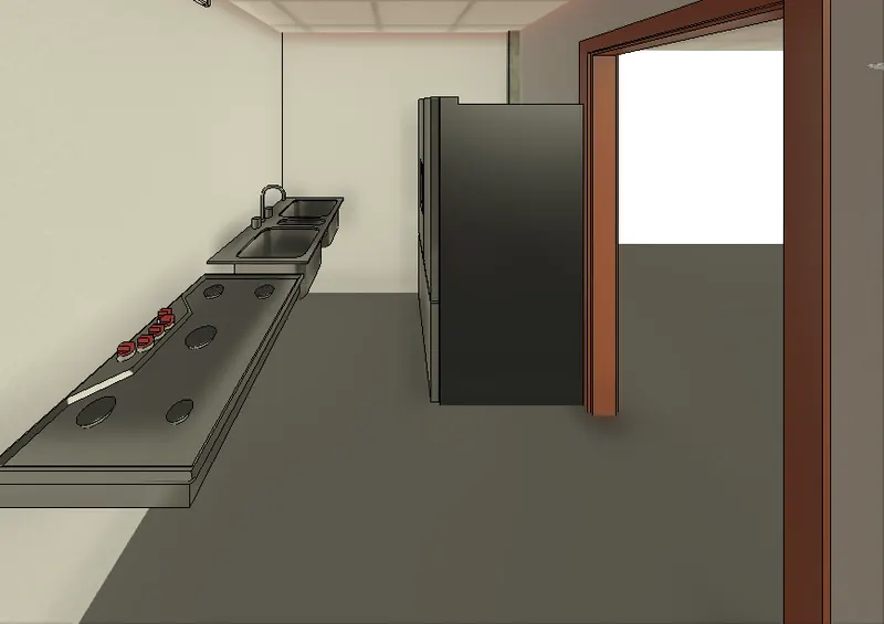
Kitchen
Dining room
Living room
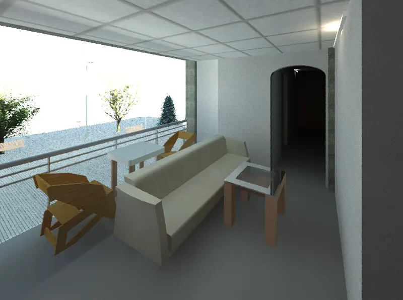
Balcony
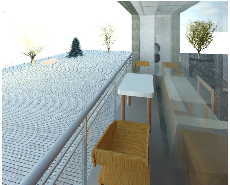
Rendering from out showing topographic features
Rendering through structural framing
7Q:Print the set of drawing sheets created and submit the drawings from the architecture and structure model
PROCEDURE:
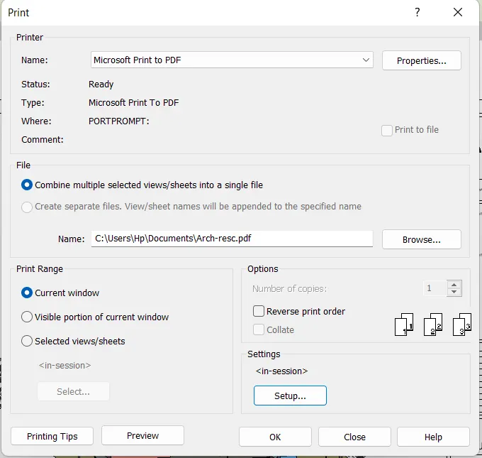
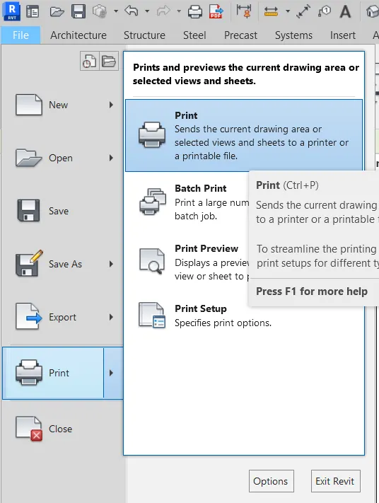
- The Print tool prints the current window, a visible portion of the current window, of selected views and sheets - You can send the desired drawings to the printer to PRIV or PLT file, or to a PDF
PROCEDURE
Step-1
- First, we use the print tool to print the drawings, as shown below.
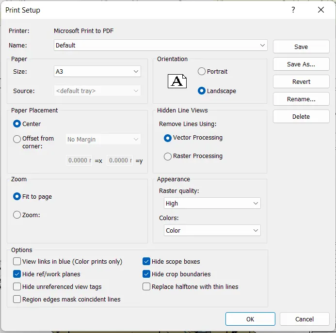
Step-2
- After printing the drawings, we can print the drawing as shown below.