Creating Architectural and Structural model with 3D rendering using REVIT
1.Select the type of structure you want to build from one of the three below:
a. Multi-Unit Residential Apartment
b. Office Buildings
c. School
ANSWER-->
From the above options option (a) Multi-Unit Residential A partment is selected for the project work
---------------------------------------------------------------------------------------------------------------------------------------------
2) Assume reasonable assumptions for geographic and location details for your project modeling. Based on assumptions and type of structure selected identify the modeling requirements from NBC
ANSWER-->
Geographic and location details for project modeling. Based on assumptions and type of structure selected identify the modeling requirements from NBC
- As above mentioned the building comes under the residential category
- Its come under group A
- Location of the project is Karnataka,Bangalore
- Geographic condition of the land is plain or flat
- The height of the multi-unit residential building is 45'
- Height, area limitations and safety measures are follwed according to NBC 2005
- Thickness of the wall , for exterior wall is 8' and for interior wall is 6'
- Width of the road is 18.5m
- Height of the building is not exceeding 1.5 times width of the road
- Hence , this project is completely safe and followed all the regulations according to NBC 2005
- So it is suitable for construction
------------------------------------------------------------------------------------------------------------------------------------------
3. AIM
Using the structural model, include the following components based on the type of structure selected
a. Foundation – Isolated / Wall/Matt Foundation
b. Columns
c. Beams Connected to Columns
d. Roof Framing/ Truss
e. Floor / Decks
f. Floor Openings for Elevators and Stairs
INTRODUCTION
- Autodesk Revit is a building information modelling software tool for architects , landscape architects , structural engineers , mechancial, electrical and plumbing (MEP) engineers, designers and contractors .
- The software allows users to design a building and structure and its component in 3D , annotate the model with 2D drafting elements , and access the building information from the building model's database.
- The revit sotware offers the following
- Revit customization and support
- Revit plugin development
- Revit mobile app development
- Custom Revit add-ins for MEP
- Some of the major advantages of revit are as follows
- parametric modelling
- collaboration
- coordination
- scheduling
- energy analysis
- rendering presentation
- construction documentation
COMMANDS USED
- Structural template
- Architectural template
- Grids
- Levels
- Beams
- Columns
- Foundations
- Floors
PROCEDURE
STEP1
- Open rivet
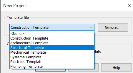
- Create a project using the structural template
- From the home page click on 'NEW'
- A dialogbox will appear from that select structural template
- Create new project
- Click ok
STEP2
CREATING GRIDS
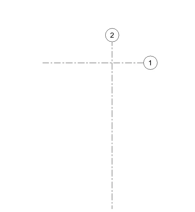
- Go to the structural tab and from that select the grid option
- draw a grid in horizontal and vertical manner , intersecting eachother
- Give name of the horizontal grid as A
- Give name of vertical grid as 1
- Save the project as 'week7 structural plan'
STEP3
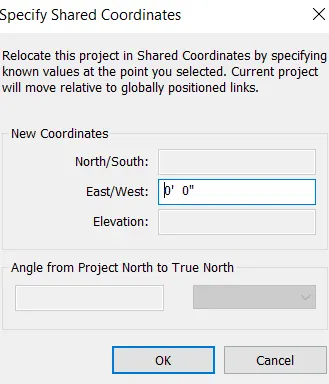
- Go to the manage tab and from that select specify the coordinates at point option
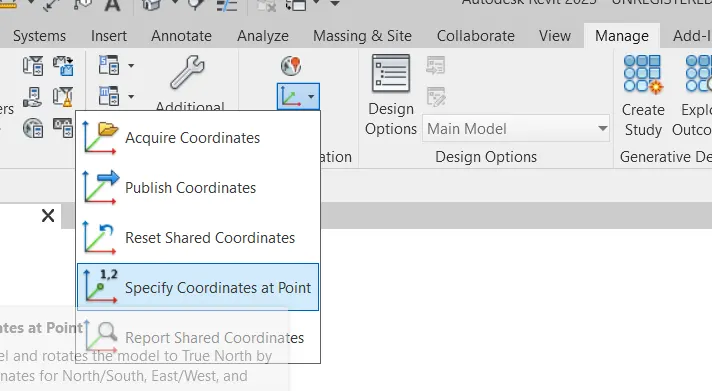
- then click on the horizontal grid , the specify shared coordinates tab will appears
- In that we need to enter the coordinates for north/south as 0
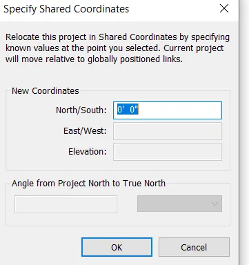
- then click on the vertical grid , the specify shared coordinates tab will appears
- In that we need to enter the coordinates for east/west as 0
STEP4
PROJECT SAVES AS CENTRAL MODEL
- Go to the collaborate tab and select collaborate
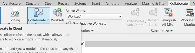
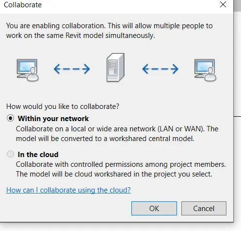
- a tab will appear and two options will be there
- from that select option within your network
- then press ok
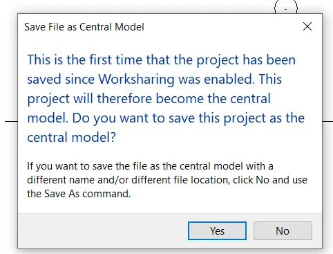
- next we need to save the project file as central model
- click save , dialog box will appear
- press yes
STEP5
Drawing levels and grids
- Offset the previously drawn grids to conveninent distance horizontaly and vertically
- Name it appropriately
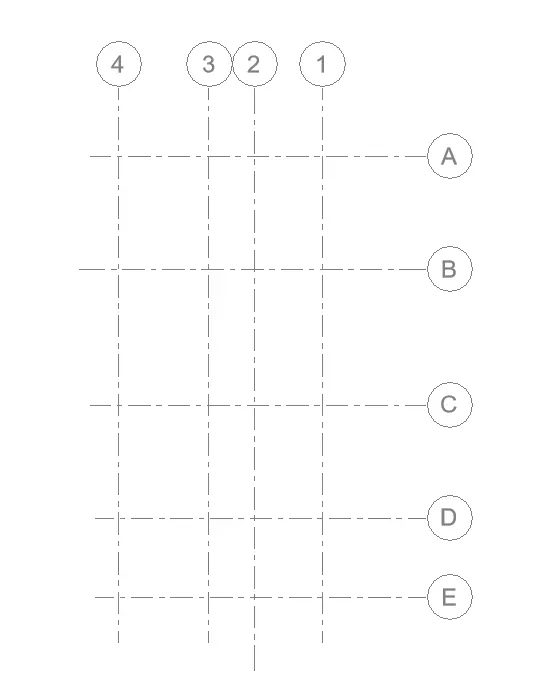
- go to the structural tab and from that select levels and create levels
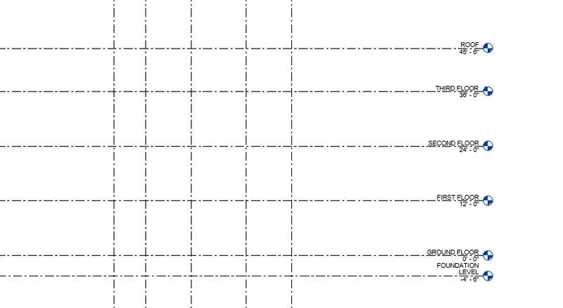
STEP6
Creating beams, columns, foundation , floor
column
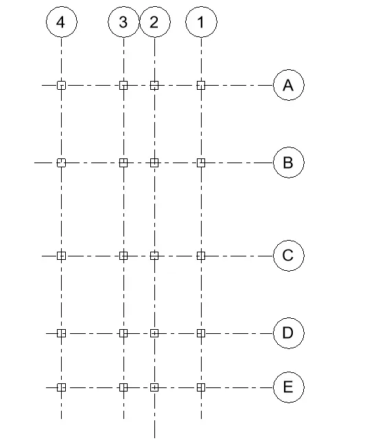
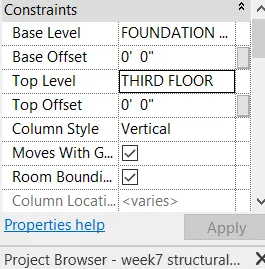
- Go to the structural tab and select column
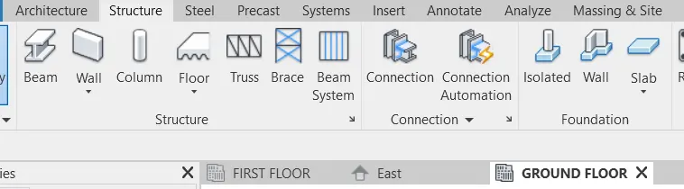
- Then we can choose vertical or slant column
- then select at grids
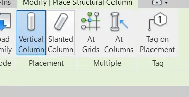
- select the grids then click finish
- Now the columns will be place at the intersection of grids
FOUNDATION
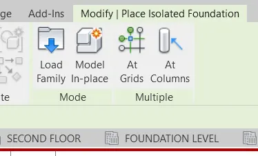
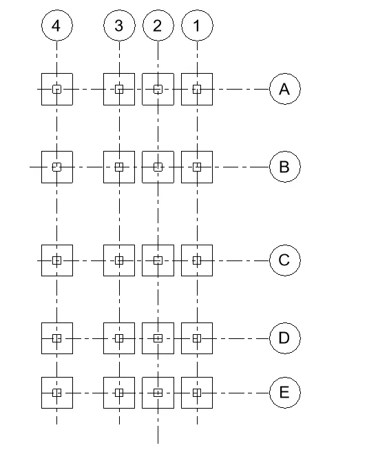
- Go to the structural tab and select the isolated footing
- then place atgrids by selcting the grids
BEAM
-
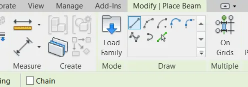
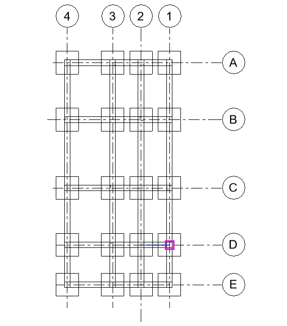
- Go to the structural tab and select the beam
- then place on grids by selcting the grids
- STRUCTURAL FLOOR
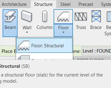
- Go to the structural tab and select the structural floor
- using rectangle draw from one corner to other corner
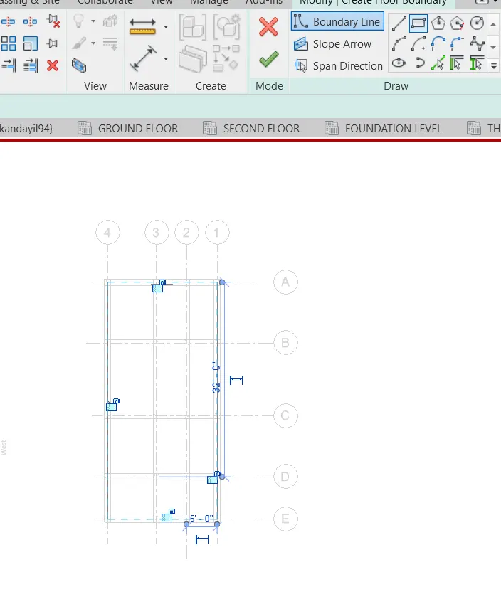
- then click finish
- same way do to the other floors also
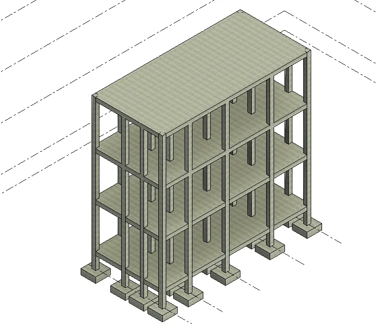
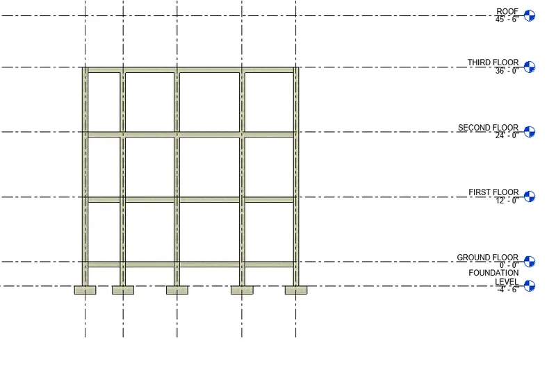
3D View
RESULT
The given components are included based on the type of structure
------------------------------------------------------------------------------------------------------------------------------------
4. AIM
Using the architectural model, include the following components based on the type of structure selected
a. Wall Layout with appropriate material and finishing
b. Exterior façade with fancy finish
c. Interior partition walls to size rooms
d. Components to add details to a room ( Desk, Chair, Lighting, Plumbing fixtures)
e. Add components such as stairs Elevators
f. Have at-least one side of the building with curtain walls and glass panels
g. Include interior and exterior lighting fixtures
h. Place proper topographic components from outside ( Trees, Parking, Plants) to add details to the model
INTRODUCTION
- Autodesk Revit is a building information modelling software tool for architects , landscape architects , structural engineers , mechancial, electrical and plumbing (MEP) engineers, designers and contractors .
- The software allows users to design a building and structure and its component in 3D , annotate the model with 2D drafting elements , and access the building information from the building model's database.
- The revit sotware offers the following
- Revit customization and support
- Revit plugin development
- Revit mobile app development
- Custom Revit add-ins for MEP
- Some of the major advantages of revit are as follows
- parametric modelling
- collaboration
- coordination
- scheduling
- energy analysis
- rendering presentation
- construction documentation
COMMANDS USED
- Architecture template
- Walls
- Components
- Load family
- Ceiling
- Floor
- Doors
- Windows
- Staircase
- Railings
PROCEDURE
STEP1
- Open rivet
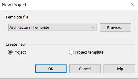
- Create a project using the architectural template
- From the home page click on 'NEW'
- A dialogbox will appear from that select architectural template
- Create new project
- Click ok
STEP2
CREATING GRIDS
- Go to thel architectural tab and from that select the grid option
- draw a grid in horizontal and vertical manner , intersecting eachother
- Give name of the horizontal grid as A
- Give name of vertical grid as 1
- Save the project as 'week7 architectural plan'
STEP3
- Go to the manage tab and from that select specify the coordinates at point option
- then click on the horizontal grid , the specify shared coordinates tab will appears
- In that we need to enter the coordinates for north/south as 0
- then click on the vertical grid , the specify shared coordinates tab will appears
- In that we need to enter the coordinates for east/west as 0
STEP4
PROJECT SAVES AS CENTRAL MODEL
- Go to the collaborate tab and select collaborate
- a tab will appear and two options will be there
- from that select option within your network
- then press ok
- next we need to save the project file as central model
- click save , dialog box will appear
- press yes
STEP5
- synchronize with the cental
- synchronize option will be visible
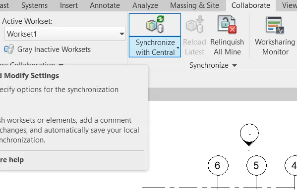
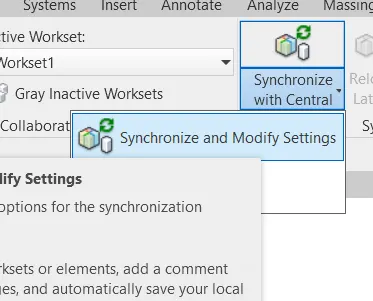
- After selecting the synchronize option a new tab will appear
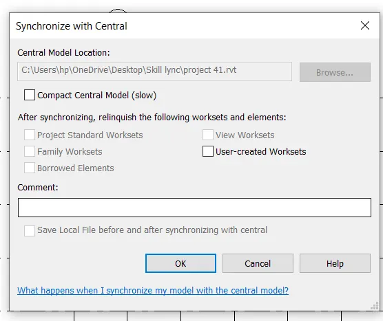
STEP6
link structrural and architectural model
- then go to the insert tab and from that select revit link
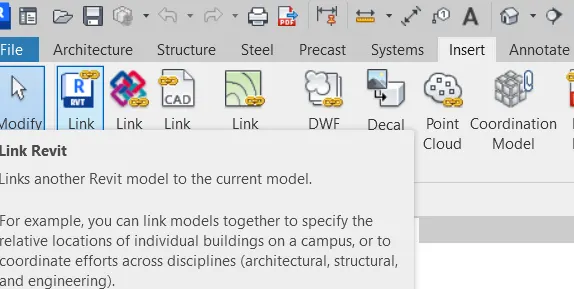
- select the structural model so that the structural model is inserted to the architectural model
- architectural tab is linked to the structural tab not copied
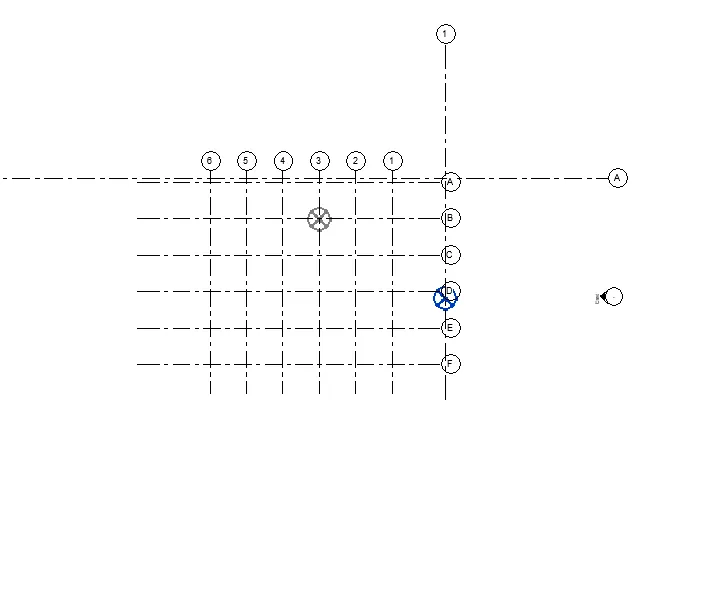
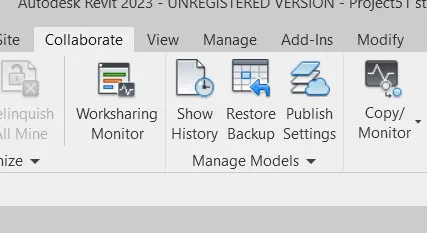
Copy/ monitor
- For that go to the collaborate from that select copy/ monitor from that click'select link'
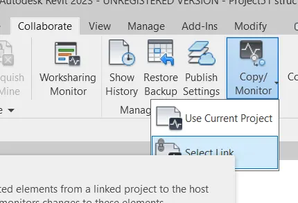
- Then click the copy option
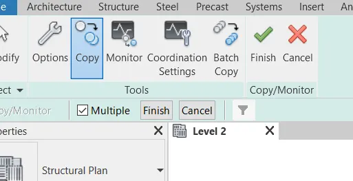
- Choose multiple and select all the grids and click finish
- select the copied grids and pin it
- Click the elevation and create the levels required for the architectiural tab
- using the 'VG' command , select custom in annotation and off the grids
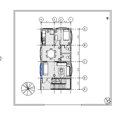
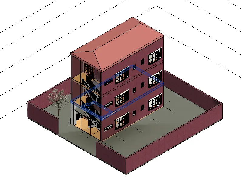
- using architectural wall add wall to all the floors
- add stairs to all the levels
- add windows and doors to the walls
- go to architecture the components - place the component-load families in the components required for the project
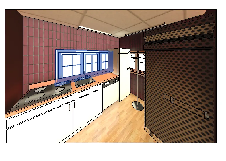
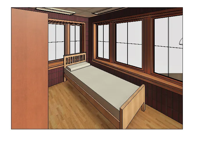
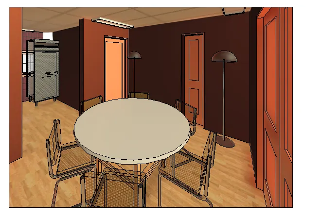
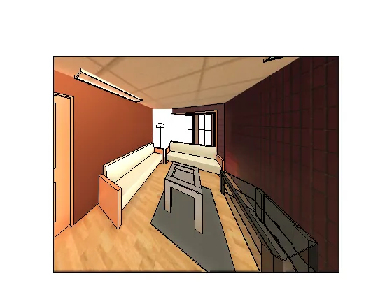
- set camera in all the room to view pictures in realistics of building
- save the project
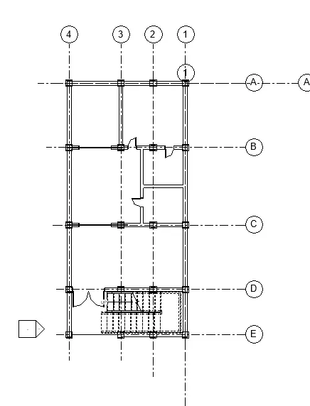
RESULT
- The given components are sucessfully included based on the type of structure using the architectural model
------------------------------------------------------------------------------------------------------------------------------------------
5. AIM
To Provide a set of drawings in an architectural and structural model to list the following details with categories and appropriate sheet templates included
a. Floor Plans with Annotations
b. Elevations
c. Sections
INTRODUCTION
- Autodesk Revit is a building information modelling software tool for architects , landscape architects , structural engineers , mechancial, electrical and plumbing (MEP) engineers, designers and contractors .
- The software allows users to design a building and structure and its component in 3D , annotate the model with 2D drafting elements , and access the building information from the building model's database.
- The revit sotware offers the following
- Revit customization and support
- Revit plugin development
- Revit mobile app development
- Custom Revit add-ins for MEP
- Some of the major advantages of revit are as follows
- parametric modelling
- collaboration
- coordination
- scheduling
- energy analysis
- rendering presentation
- construction documentation
COMMANDS USED
- Insert
- Sheets
- Load families
- Edit sheets
- Load image
- View
PROCEDURE
STEP1
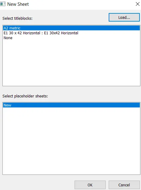
- Click on the sheet option in the viewtab
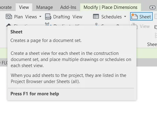
- After clicking the sheet option the new sheet tab will be visible in the screen
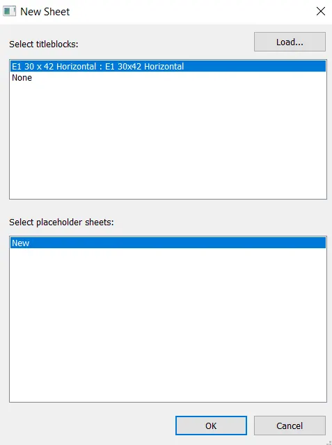
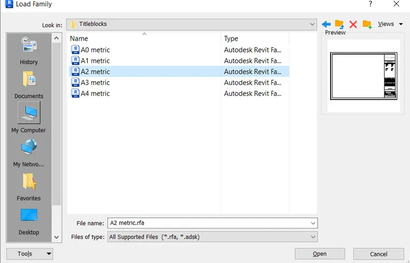
- then load the sheet as per the requirement
- select the loaded sheet and sheet will be displayed
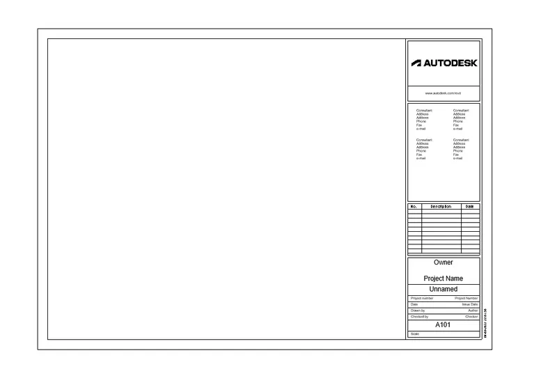
- Edit and change the data in the sheet as per requirement
STEP2
FLOOR PLANS
- Edit and change the data in the sheet as per requirement
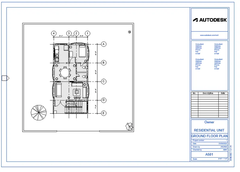
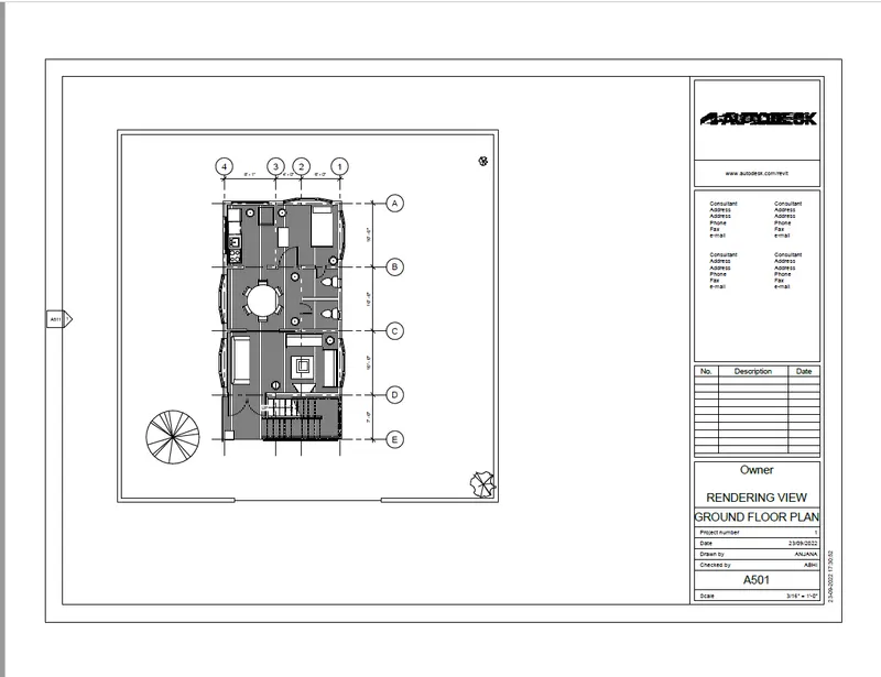
- First adding ground floor plan to the sheet A-501
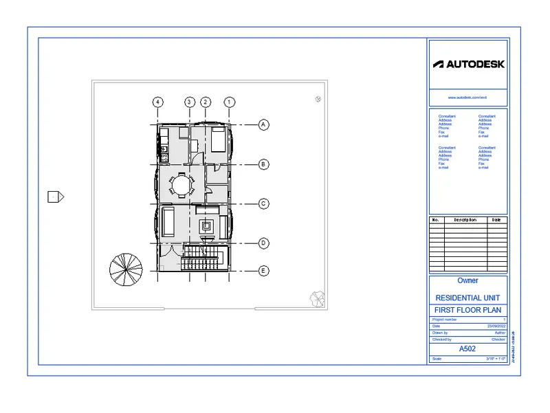
- Adding first floor plan to the sheet by draging the view to the sheet A502
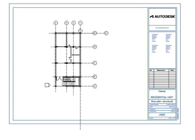
- Next we add ground floor structural plan to the sheet by dragging it into the sheet A-503
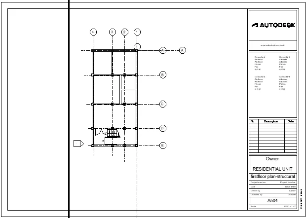
- Next we add first floor structural plan to the sheet by dragging it into the sheet A-504
SECTIONS
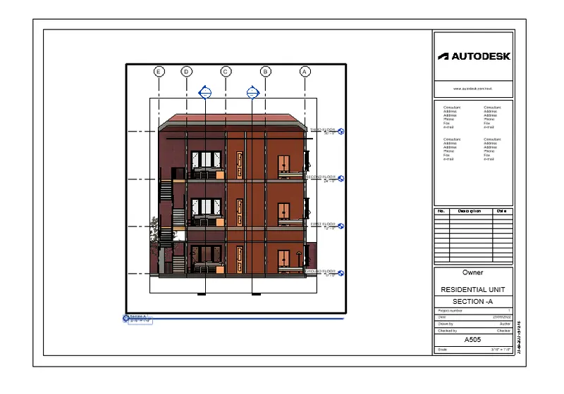
- Next we add section-A to the sheet A-505
- next we add section -B to the sheet A-506
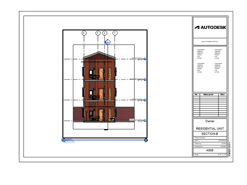
- next we add section -C to the sheet A- 507
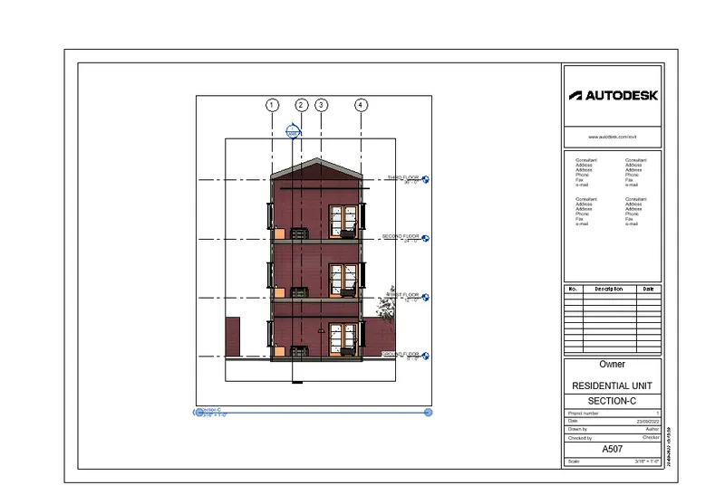
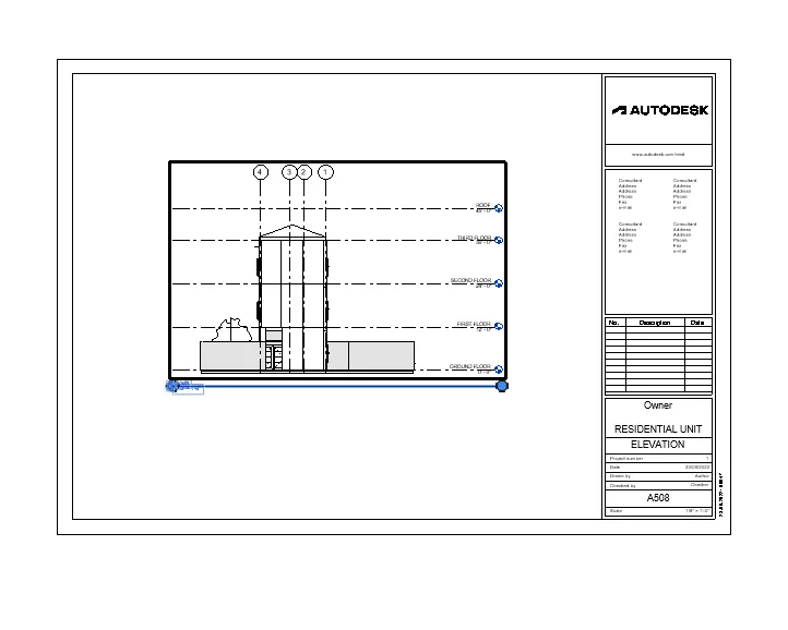
ELEVATIONS
- next we have to add front elevation to the sheet A-508
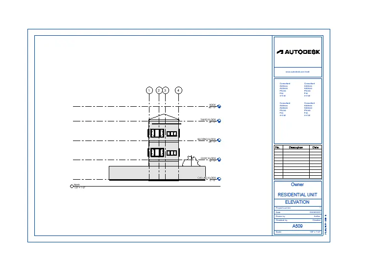
- next we have to add back elevation to the sheet A-509
- next we have to add side elevation to the sheet A-510
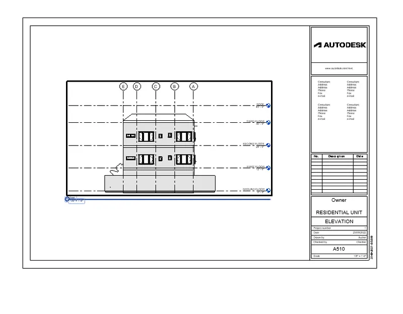
- next we have to add side elevation to the sheet A-511

RESULT
Provided a set of drawings in an architectural and structural model and listed the following details with categories and appropriate sheet templates included
--------------------------------------------------------------------------------------------------------------------------------------------
6. AIM
Using the Rendering settings, Render images of the 3D model produced and include the rendered images to the drawing sheets
INTRODUCTION
- Render the view to create a photorealistic image of the 3D model
- After preparing the 3D view and using the rendering dialog to select desired settings, click render to render the image
- Revit begins the rendering process , rendering the entire image progressively
- Revit displays a progress dialog box, which shows information about the rendering process
COMMANDS USED
- Render
- Region
- Style
- Scheme
- Sheet
PROCEDURE
STEP1
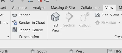
- for rendering go to the view render or by using RR command
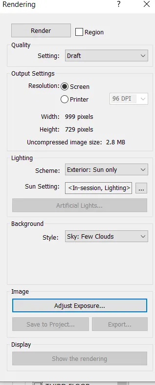
- Dialogbox will appear and adjust it and render
- save the rendered image
STEP2
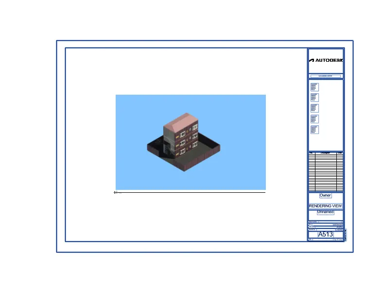
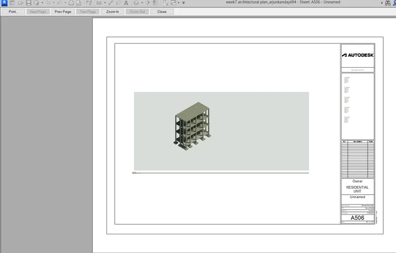
- First we can add rendering view residential building to the sheet
- next we can add rendering view of kitchen to the sheet
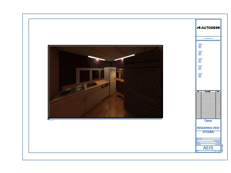
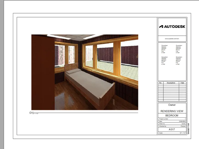
- next we can add rendering view of bedroom to the sheet
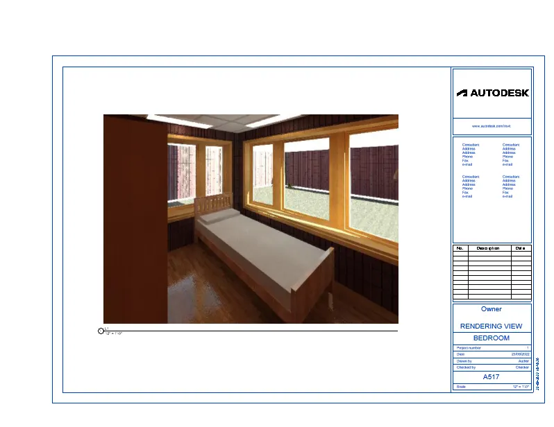
- next we can add rendering view of dinning room to the sheet
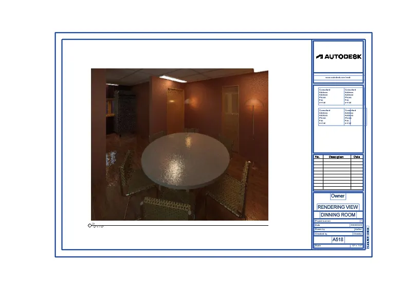
- next we can add rendering view of living room to the sheet
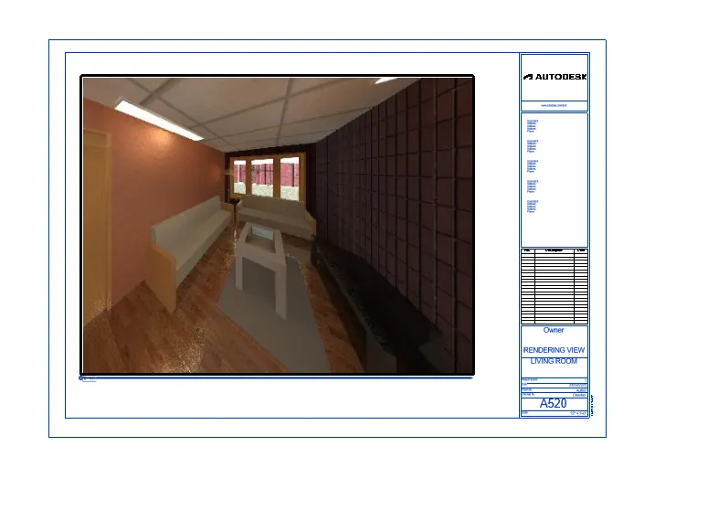
- next we can add rendering view of structural framing to the sheet
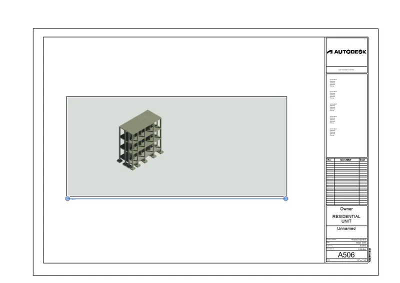
RESULT
Rendered images of the 3D model produced and included the rendered images to the drawing sheets
-------------------------------------------------------------------------------------------------------------------------------------------
7. AIM
To Print the set of drawing sheets created and submit the drawings from the architecture and structure model
INTRODUCTION
- Use the print tool to print selected views and sheets
- You can send the desired drawings to the printer , to a PRN or PLT file or to a PDF file
COMMANDS USED
- File
- Setup page
PROCEDURE
STEP1
- we need print tool to print the drawings
- for that use ctrl+p
- a dialog box will appear
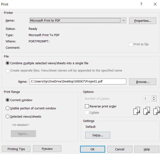
- in that select page setup to adjust the page
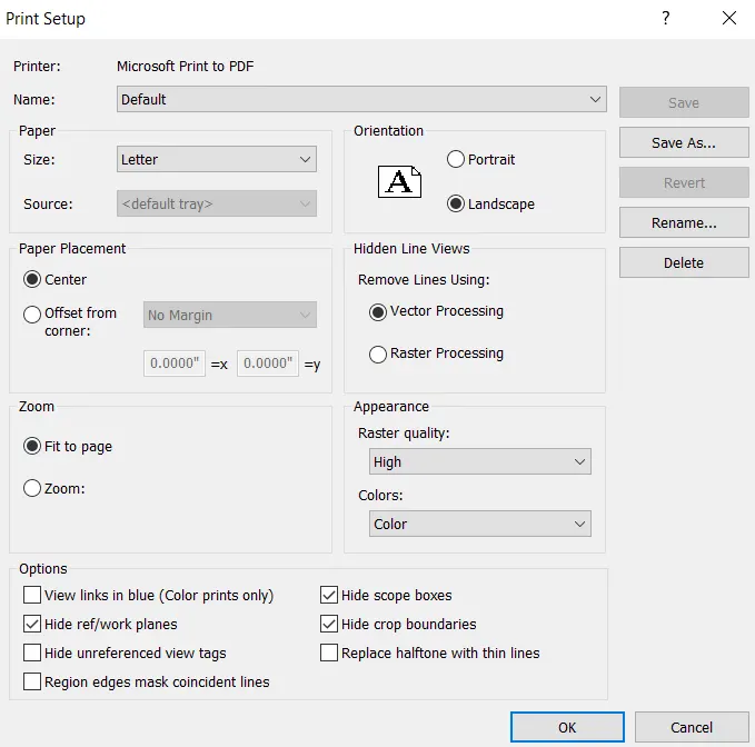
STEP2
- After printing the drawings , we open the printed drawings as shown below
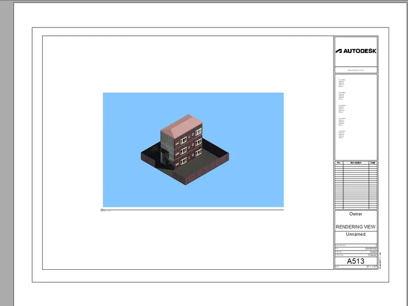
RESULT
- The set of drawing sheets created
- submited the drawings from the architecture and structure model
---------------------------------------------------------------------------------------------------------------------------------------------