Creating Architectural and Structural model with 3D rendering using REVIT
1) Select the type of structure you want to build from one of the three below:
a. Multi-Unit Residential Apartment
b. Office Buildings
c. School
My model represent the Multi-resident apartment
Aim:
To build from one Multi-Unit Residential Apartment
Commands Are used:
- Architecture
- Wall
- Ceiling
- Annotate
- Wall
- Door
- Railing
- Insert
Procedure:
- First We select the architectural tab create the new drawing
- And we do save the file name as project
- Change the dimension to the unit as feet
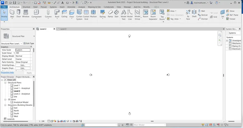
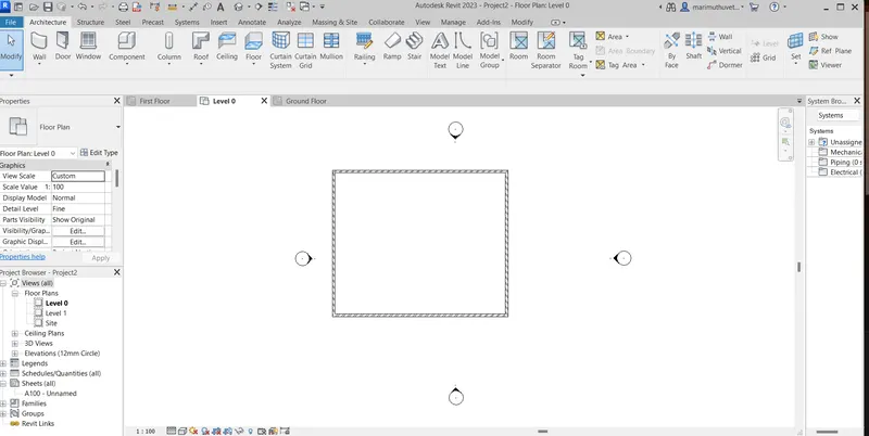
- Have create the outer layout 36'x34' feet respectively
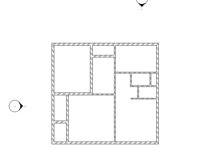
- I give the partion over the layout
- I go for an 2 bed room 1 kitchen 1 balcony the lift wall and foyer
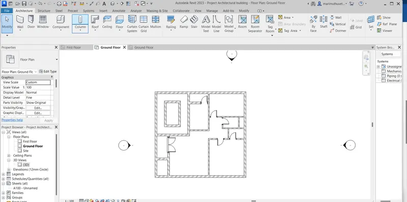
- Next we provide the windows and the the door at the respective dimension
- Next we proceed with the staircase we provide the staircase over the lift wall
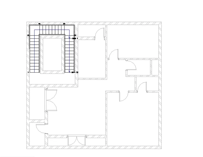
- We gives the lift for an purpose of the residential unit purpose
- To add the furniture and the tv units
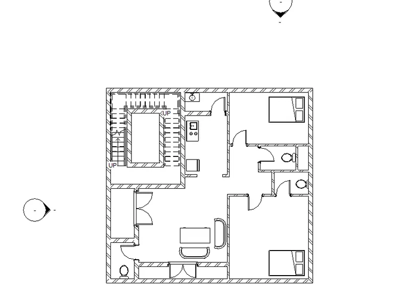
Once we check the 3d view

To give the annotation to the outer layout boundary
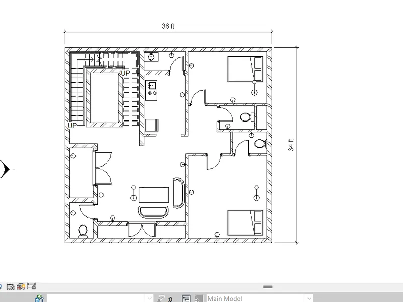
To copy the ground floor plan to the level 1
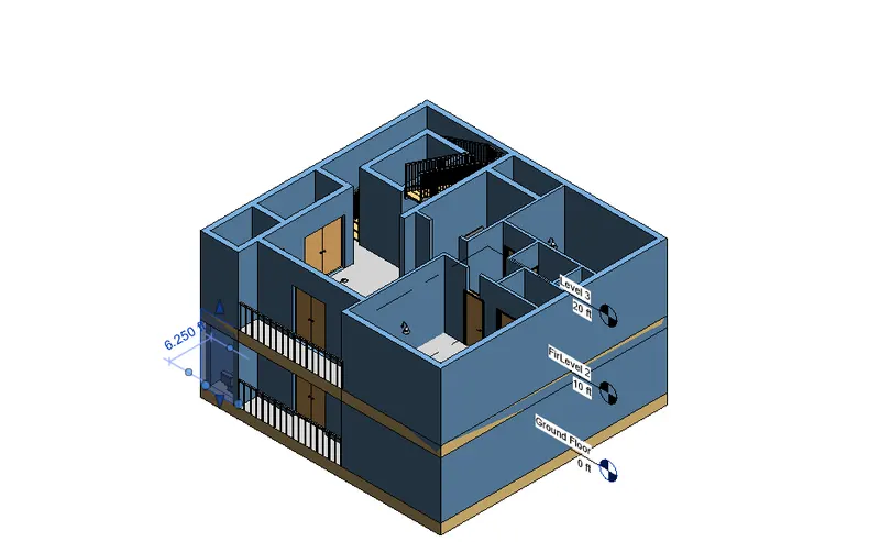
To create the roof and the tophographic view
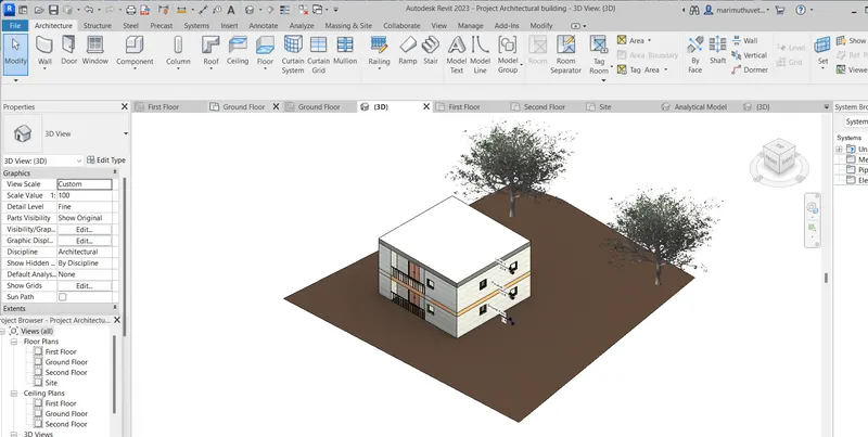
RESULT:
Finally we draw the architectural drawing multi residential unit
Aim:
To build from one Multi-Unit Residential Apartment
Commands Are used:
- Strcture
- Wall
- Ceiling
- Column
- Beam
- Door
- Insert
Procedure:
- First We select the Strctural tab create the new drawing
- And we do save the file name as project
- Change the dimension to the unit as feet
- To craete the grid as per the dimensions
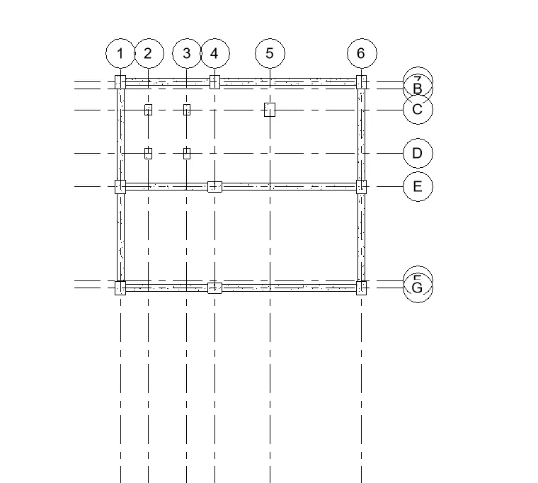
To click the column to fix it
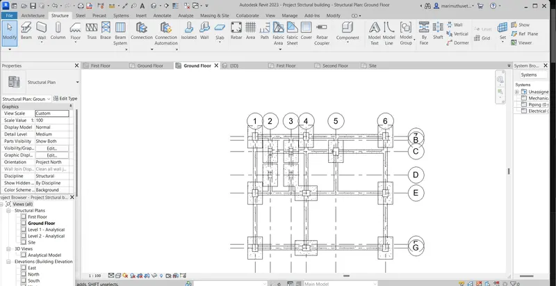
After the fix of the column and the beam to create the wall
To check the 3d view
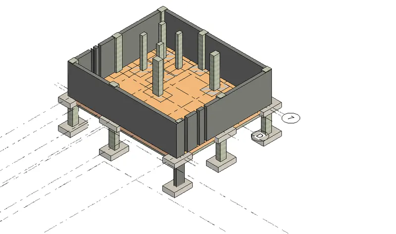
RESULT:
Finally we draw the Strctural plan drawing
2) Assume reasonable assumptions for geographic and location details for your project modeling. Based on assumptions and type of structure selected identify the modeling requirements from NBC
- To be the open space area around the building should not less than 4.5m
- As mentioned my building comes under residential category and it can be situated in the center of the city.
- The road width and the length in front of my building is 36'x34'
- The height, area and safety measures will follow the rules and regulations of NBC.
- The height of my project is 24'
- So my building height is 8 m and the road width is 12m, the height of the building should not exceed 1.5 times the width of the road width.
- In this case the building height is not exceeding so it is suitable for construction.
3) Using the structural model, include the following components based on the type of structure selected
a. Foundation – Isolated / Wall/Matt Foundation
b. Columns
c. Beams Connected to Columns
d. Roof Framing/ Truss
e. Floor / Decks
f. Floor Openings for Elevators and Stairs
Aim:
To using the structural model, include the following components
Commands Are used:
- Strcture
- Wall
- Ceiling
- Grid
- Level
Procedure:
- First We select the Strctural tab create the new drawing
- And we do save the file name as project
- Change the dimension to the unit as feet
- First we created the outer boundary layer
- After we created the grid
- To create the Foundation – Isolated / Wall/Matt Foundation
Next we created the Columns
And we connected to the beams
After the confirmation to check the 3d view
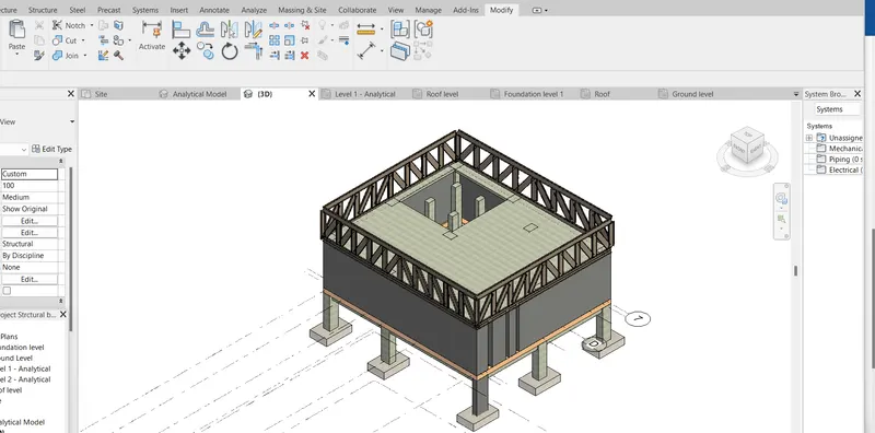
To click the floor tab and placed it
Next we click the roof framing
To create the Floor Openings for Elevators and Stairs
RESULT:
Finally we draw the all components given drawing
4) Using the architectural model, include the following components based on the type of structure selected
a. Wall Layout with appropriate material and finishing
b. Exterior façade with fancy finish
c. Interior partition walls to size rooms
d. Components to add details to a room ( Desk, Chair, Lighting, Plumbing fixtures)
e. Add components such as stairs Elevators
f. Have at-least one side of the building with curtain walls and glass panels
g. Include interior and exterior lighting fixtures
h. Place proper topographic components from outside ( Trees, Parking, Plants) to add details to the model
Aim:
To Using the architectural model, include the following components
Commands Are used:
- Architecture
- Wall
- Ceiling
- Annotate
- Wall
- Door
- Railing
- Insert
Procedure:
- First We select the architectural tab create the new drawing
- And we do save the file name as project
- Change the dimension to the unit as feet
- Have create the outer layout 36'x34' feet respectively
- I give the partion over the layout
- I go for an 2 bed room 1 kitchen 1 balcony the lift wall and foyer
- Next we provide the windows and the the door at the respective dimension
- Next we proceed with the staircase we provide the staircase over the lift wall
- We gives the lift for an purpose of the residential unit purpose
- To add the furniture and the tv units
To check the Wall Layout with appropriate material and finishing
To give the annotation to the outer layout boundary
To copy the ground floor plan to the level 1 and gives the wall as the exterior facde
Go for an annotae tool and gives Interior partition walls to size rooms
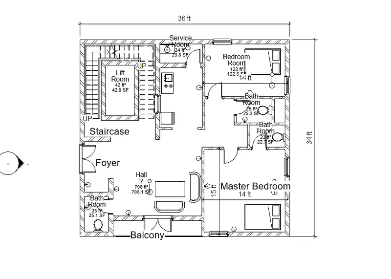
To add the componets of the chair desk all of tis things
To add the staircase over the lift wall
To create an one wall at the certain wall
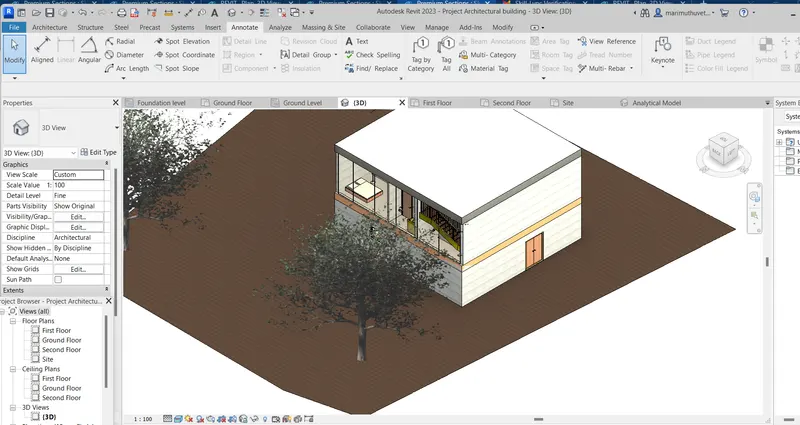
To Include interior and exterior lighting fixtures
To create the roof and the tophographic view
RESULT:
Finally We draw an following given components
5) Provide a set of drawings in an architectural and structural model to list the following details with categories and appropriate sheet templates included
a. Floor Plans with Annotations
b. Elevations
c. Sections
Aim:
To provide the strctural and architectural drawing
Commands Are used:
- Architecture
- Wall
- Ceiling
Procedure:
Floor Plan Drawings:
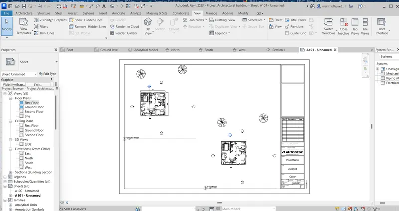
The drawing will be Architectural drawing
The Drawing will be Strcural drawing
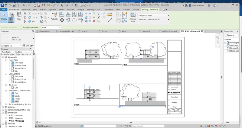
The elevation drawings
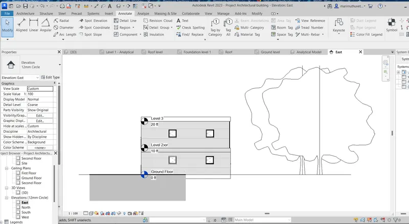
This is an architectural east drawing
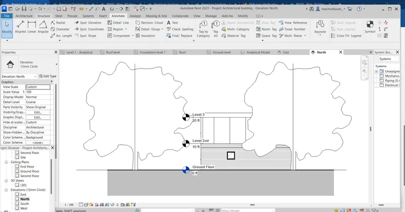
This is an architectural north drawing
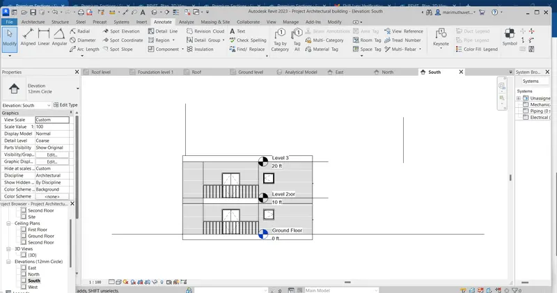
This is an architectural south drawing
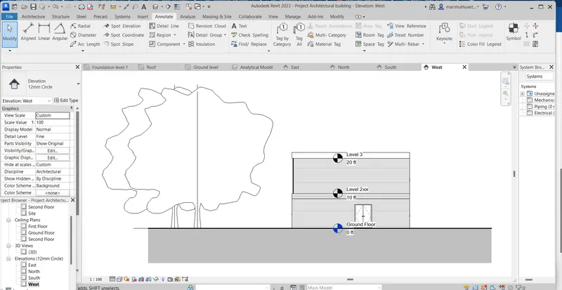
This is an architectural west drawing
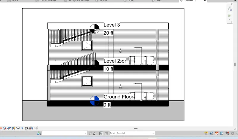
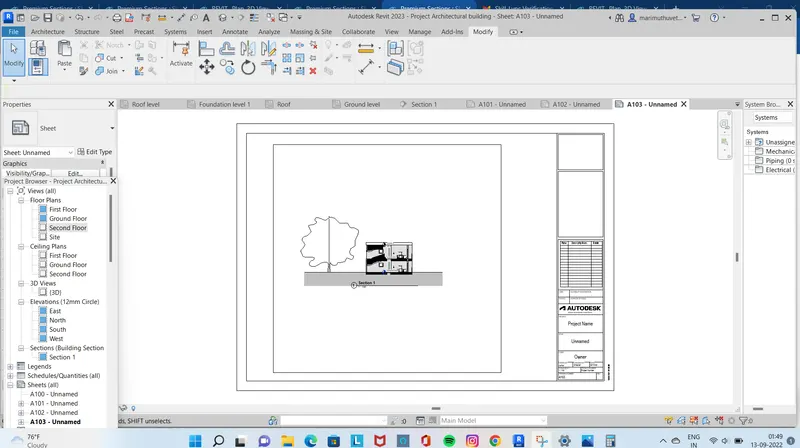
This is an architectural section drawing
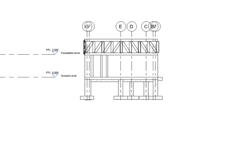
This is an structural east drawing
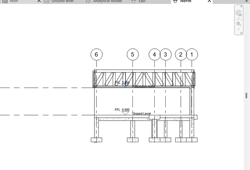
This is an structural north drawing
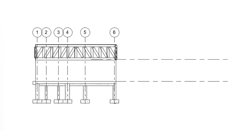
This is an structural south drawing
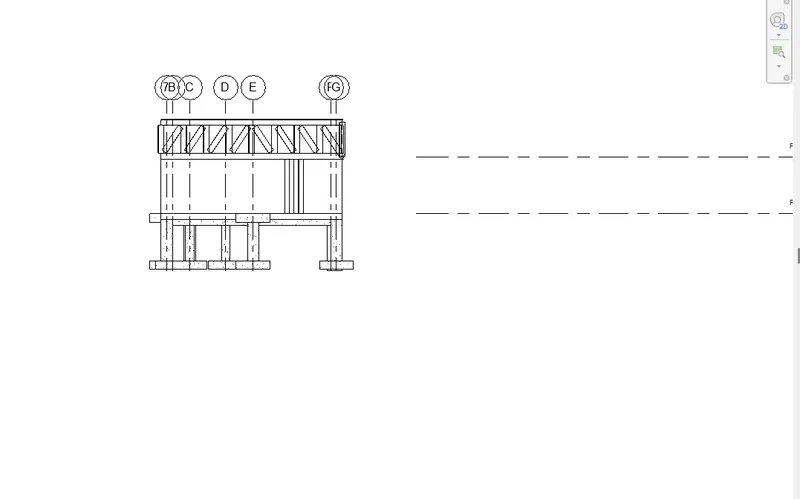
This is an structural west drawing
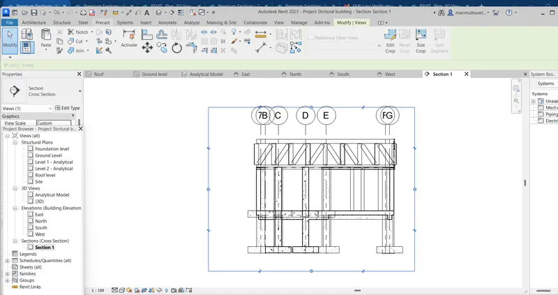
This is an structural section drawing
RESULT:
Finally we draw the all the components of the drawings
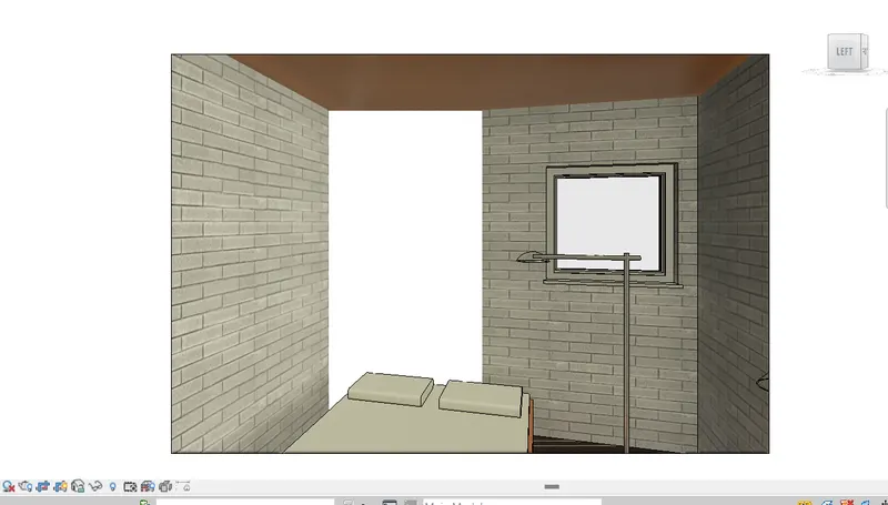
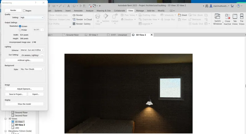
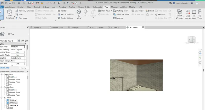
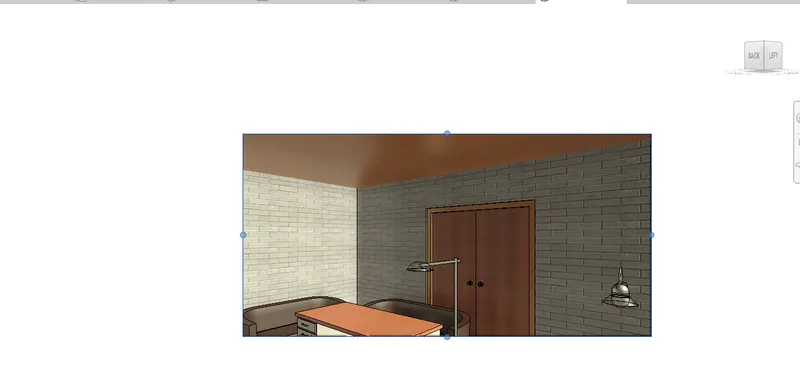
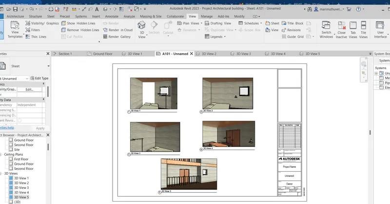
6) Using the Rendering settings, Render images of the 3D model produced and include the rendered images to the drawing sheets
a. Rendering from interior rooms
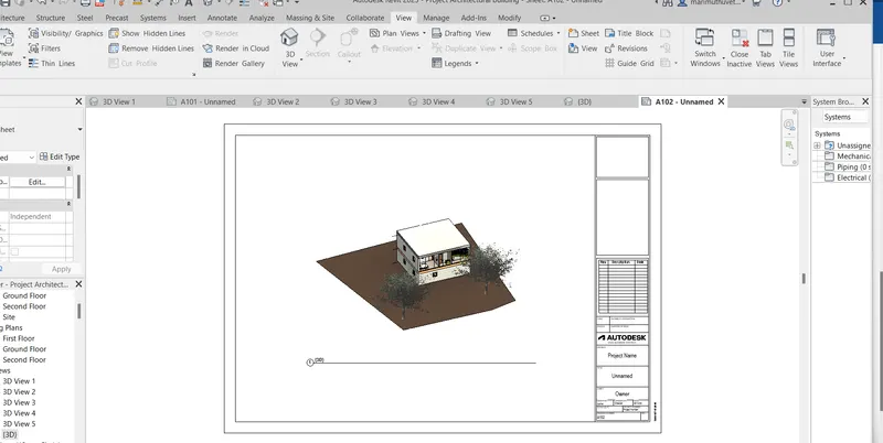
b. Rendering from out showing topographic features
c. Rendering through structural framing
Aim:
To Using the Rendering settings, Render images of the 3D model produced and include the rendered images
Commands Are used:
- Architecture
- Wall
- Rendering
Procedure:
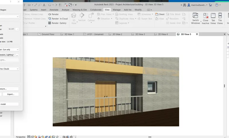
- Created the architectural drawing
- Go to the view to the camera where it as wants placed it
- Thats will mentioned as 3d view 1 and 2
- To click the rendering option
RESULT:
Finally we render the drawings and adding to the sheet
7) Print the set of drawing sheets created and submit the drawings from the architecture and structure model
Aim:
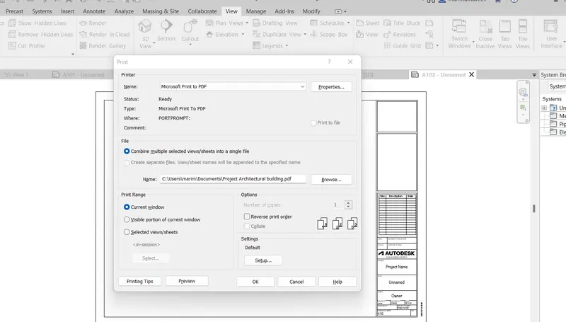
To print the the set of drawing sheets created and submit the drawings
Procedure:
- To click the print option
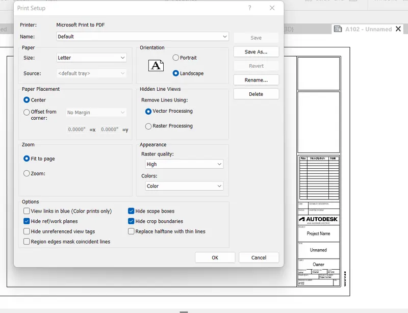
- And go for an page set up once check the box
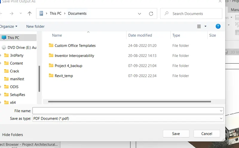
- Want to save the file click the microsoft as pdf option to save it
RESULT:
Finally we print the revit drawing to the pdf