Creating Architectural and Structural model with 3D rendering using REVIT
1) Select the type of structure you want to build from one of the three below:
a. Multi-Unit Residential Apartment
b. Office Buildings
c. School
Ans 1. The selected building structure is a Multi-unit Residential Apartment Parking + 6 floors for the project work.
2) Assume reasonable assumptions for geographic and locration details for your project modeling. Based on assumptions and type of structure selected identify the modeling requirements from NBC
Ans 2. The Parking + 6 floors structure is located in Nashik, Maharastra State.
- The plot size is 262sqm and it is a 2 road corner plot
- As per bye laws and NBC code the FAR is 1.1 times plot area and additional area for construction can be availed by paying the Premium and anciliary charges and buying TDR thus taking the FAR to maximum of 3.2 times plot area
- Thus we have considered area of 840sqm which is within the permissible limit.
- There is a one 3BHK residential unit on one floor.
- The mandatory number of Parkings for 2 wheeler and 4 wheelers is provided at ground floor level as per the local bye laws and NBC standard requirement
- The room size and areas provided are more than the minimum area specified in the NBC standard
- The side margins from boundary wall and set back distance from the roads are H/5 for buildings above 15m height thus in our case the set back distance is 3.5m for building height of 17.40m as per 2.90m height of each floor which is more than 2.75m height requirement as per NBC.
- Staircase width of 1.20 m is maintained as per the bye laws requirement.
- One Elevator is provided as per the mandatory requirement for building above 15m height.
3) Using the structural model, include the following components based on the type of structure selected
a. Foundation – Isolated / Wall/Matt Foundation
b. Columns
c. Beams Connected to Columns
d. Roof Framing/ Truss
e. Floor / Decks
f. Floor Openings for Elevators and Stairs
Ans 3.
INTRODUCTION: Creating a Structural model for the building structure selected.
AIM: To create the structure model fo the residential building selected including the following components for the structure selected
- The isolated foundations to be provided for the columns and matt foundation to be provided for lift shaft walls
- The rectangular concrete columns to be considered for the structure
- Rectangular concrete beams to be considered and connected to the columns at different levels.
- Roof of RCC concrete slab is to be provided.
- RCC slabs to be considered for the slab
- Floor openings are to be created in the slab at all levels using shaft command for staircase, lift shaft and plumbing shafts.
PROCEDURE:
- The procedure for creating the Structural model mentioned below along with the screenshots for various steps.
- The architectural floor plans and elevations are defined in the architectural model prior to starting to create the Structural model.
- The grid lines are also provided in the architectural plans.
- Now open a new project in Structural template
- Link the Architectural project from the Insert tab and Link Revit file
- The Architectural plan view will be visible on the structural template.
- On Home tab create 3D view.
- Click on Collaborate tab
- Click on Copy/ Monitor tab and click on the Select lin
- Select the 3D view, the Copy/Monitor ribbon will be opened at top
- Click on Copy tab
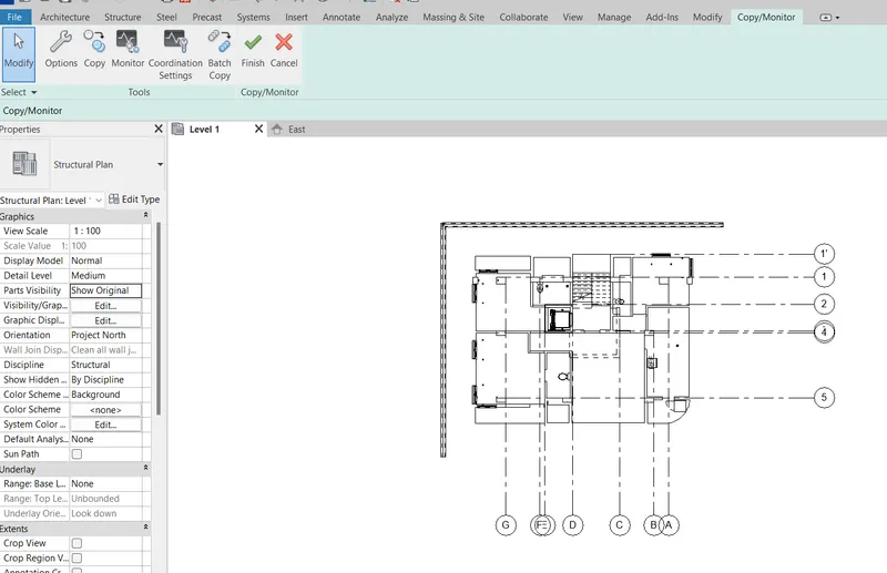
- Then select the Multiple option check mark
- Then select all the elements on the drawing view
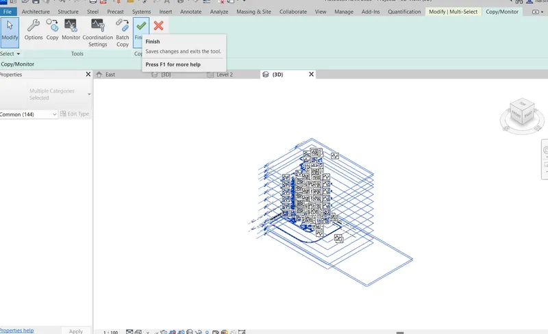
- Click Finish.
- The again click on the copy monitor and click on the upper Finish tab
- Go to View Tab and select the Floor plan views or Structural plan views from the architectural model linked
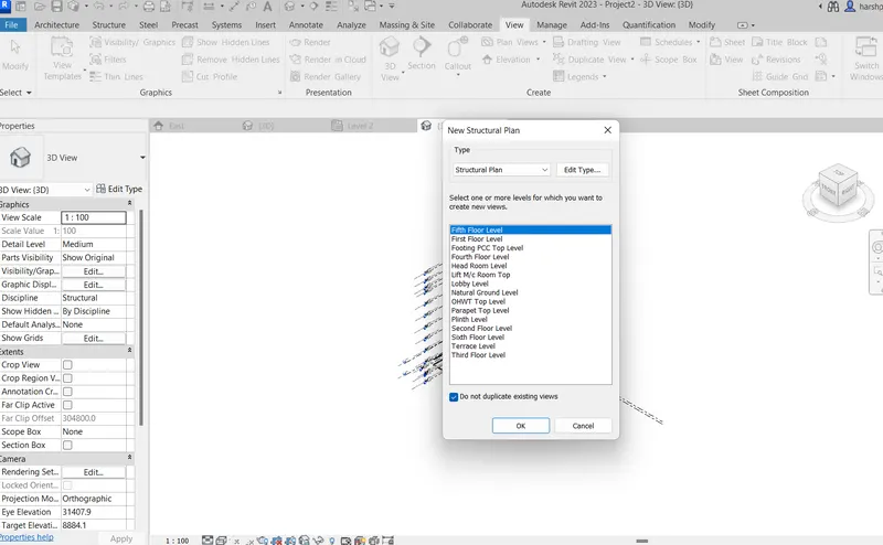
- Thus the structural plan view list is visible in the project browser
- By selecting the Discipline to Coordination we can view the Architectural elements in the plan
- By selecting the Discipline to Structural, only structural elements will be seen
- We can manage the Revit link on or off from Visibiiity graphics and Revit links tab
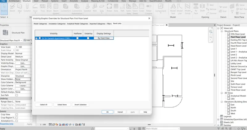
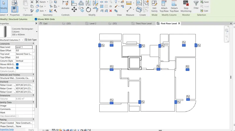
- The default columns are seen in the plan view which can be changed to required concrete column elements by selecting the column from the list of available column types in properties or by creating the required size of column
- The limits of column height are defined in the properties
- We have considered the limit of column from foundation level to terrace level
- The above terrace columns are selected later and adjusted to required elevation for headroom slab
- Beam grid can be created by clicking Beam in the Structural model veiw by selecting the beam type in the properties or creating the required size of the beam
- The beams are connected from column to column to form grid and cantilevers are also created for supporting the structure outside the column line
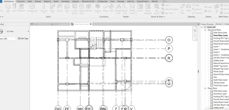
- Thus beam grid is created at plinth level and parking (First floor) level separately as per required structure
- Similarly the beam grid is created at the Second floor level for typical slab.
- The Typical slab beam grid levels are then copied to Clip board and pasted at upper levels upto terrace slab
- The floor is created at the one level from outer to outer of the beam grid by providing the required properties for material and thickness of slab.
- Similarly the floors are also copied to clipboard and pasted to required levels
- Now the openings for the Staircase shaft, Elevator shaft and Plumbing shaft are created by drawing the boundaries on the slab and specifying the height or levels for the shaft by using Shaft command.
- Thus the various views of the structural framing work created is shown below in the screenshots.
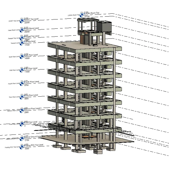
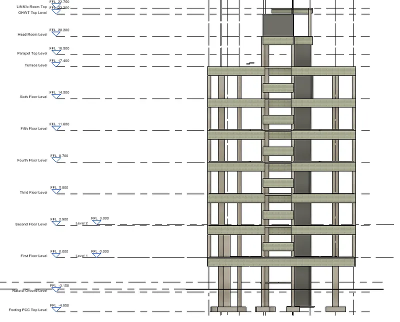
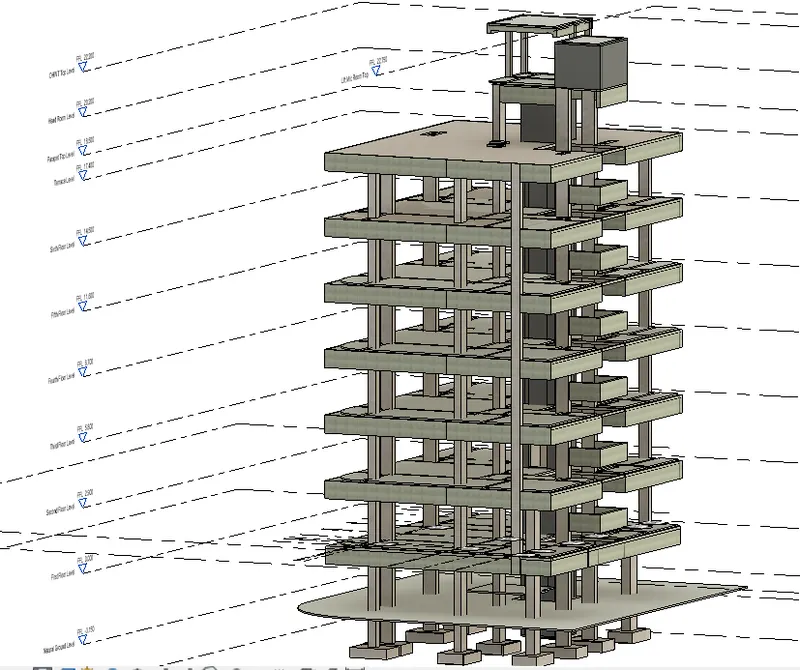
- The coordination view before creating the structural floors is shown below
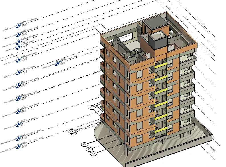
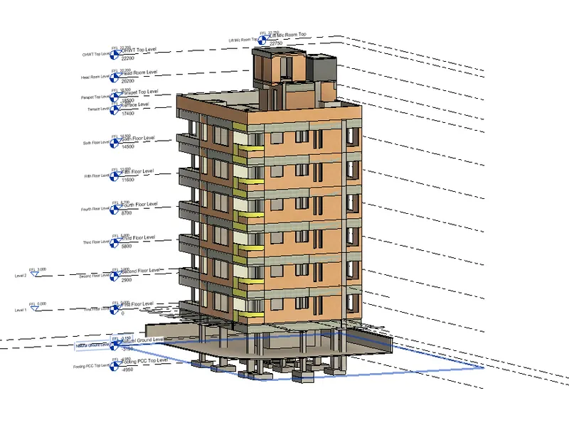
CONCLUSION: Thus we have create the Structural model for the selected Parking +6 floors residential unit from the Architectural plan views using various tools by Linking the revit files and by using Copy/Monitor tool from Collaborate tab
4) Using the architectural model, include the following components based on the type of structure selected
a. Wall Layout with appropriate material and finishing
b. Exterior façade with fancy finish
c. Interior partition walls to size rooms
d. Components to add details to a room ( Desk, Chair, Lighting, Plumbing fixtures)
e. Add components such as stairs Elevators
f. Have at-least one side of the building with curtain walls and glass panels
g. Include interior and exterior lighting fixtures
h. Place proper topographic components from outside ( Trees, Parking, Plants) to add details to the model
Ans 3.
INTRODUCTION: Creating an Architectural model for the building structure selected.
AIM: To create the architectural model fo the residential building of Parking + 6floors selected including the following architectural components for the structure selected
- The wall to be considered as brick wall of 150mm thickness for external walls and 100mm thickness for internal partion walls.
- External facade treatment to be provided for the shaft openings in elevation
- Curtain walls to be provided to the entrance lobby
- Furniture and plumbing fixtures to be provided
- Staircase to be provided
- Internal and external lighting fixtures to be provided
- Rectangular concrete beams to be considered and connected to the columns at different levels.
- Trees to be provided
PROCEDURE:
- Open an architectural template.
- Create a floor plan for the residential typical floor
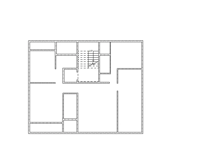
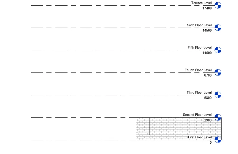
- Create elevations with the height of floors as 2.90m
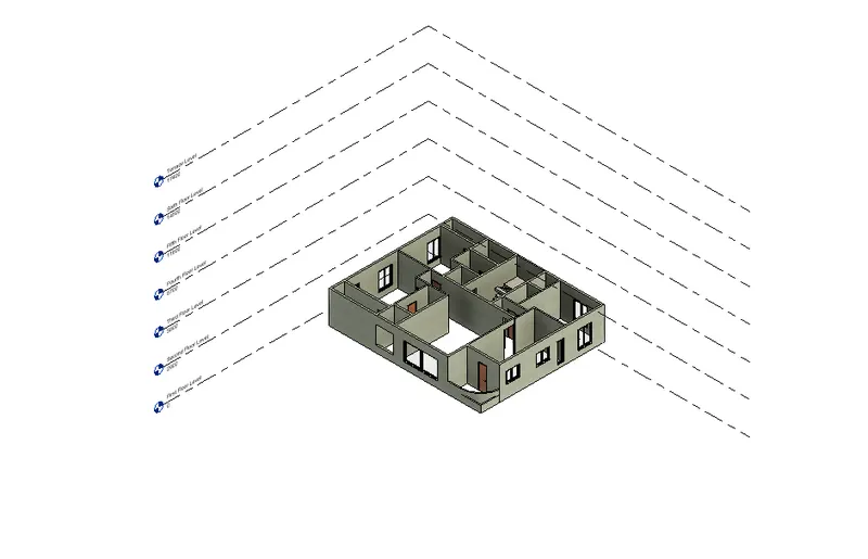
- Create internal and external wall elements as per the room size
- Provide the doors and windows for the rooms by loading the family for doors and windows
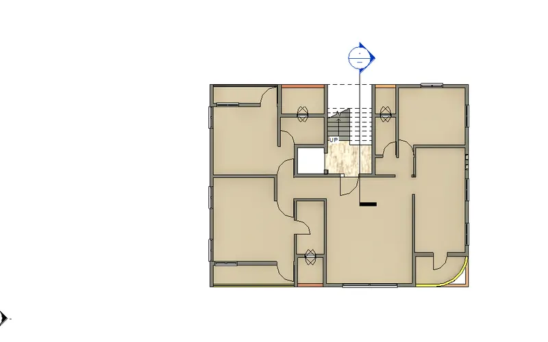
- Provide the floor by selecting the floor boundaries for different room areas
- Provide the furniture elements in the plan
- If required colour the wall in the single floor layout so that same will be repeated to upper floors after copy pasting
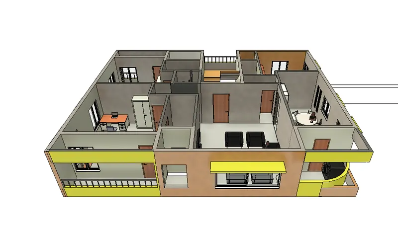
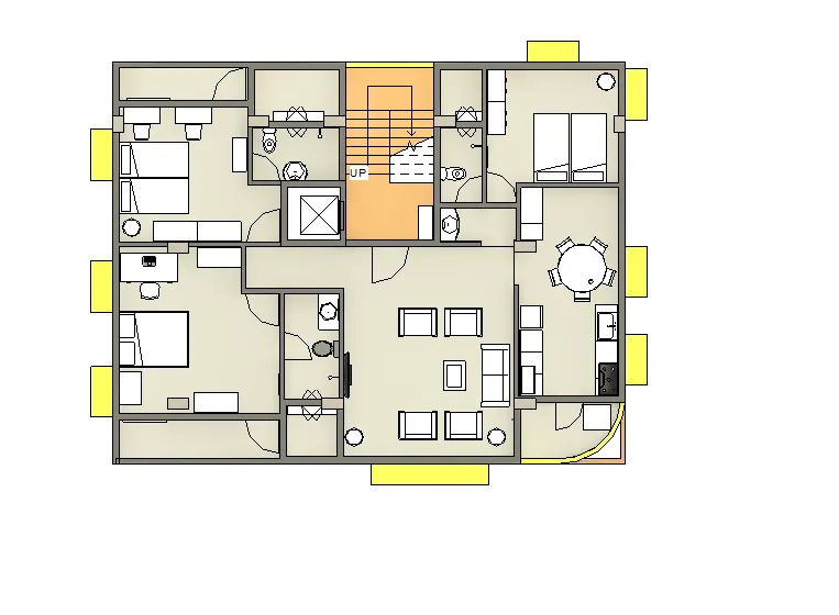
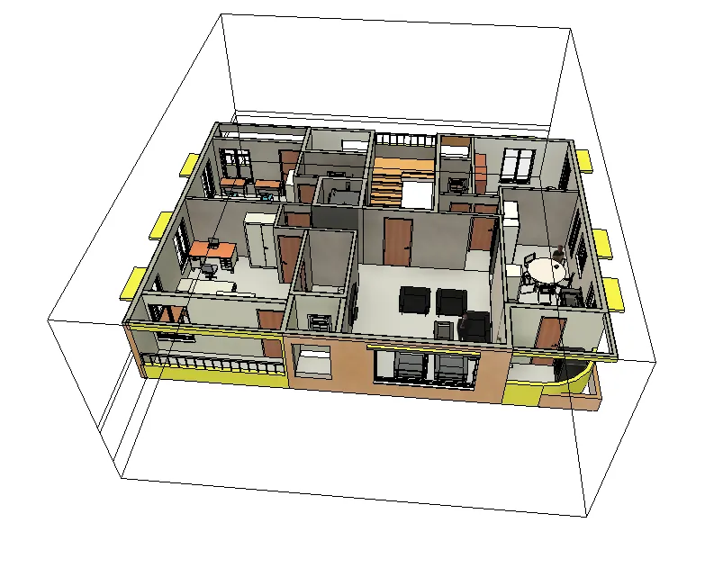
- Section box in properties can be selected to cut the desired sections of the model
- Copy the typical floor layout with all the elements and paste in the upper floor levels
- Create the parking level and below ground levels
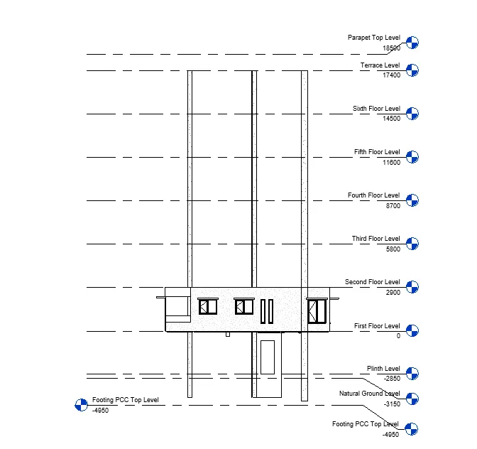
- The floor can also be groupd and shifted to upper floors.
- If any change is made by edit group command then the changes will reflect in the groups at all floor levels.
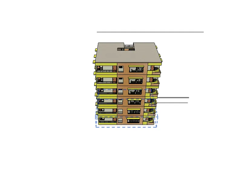
- Create the plinth floor and entrance lobby layout
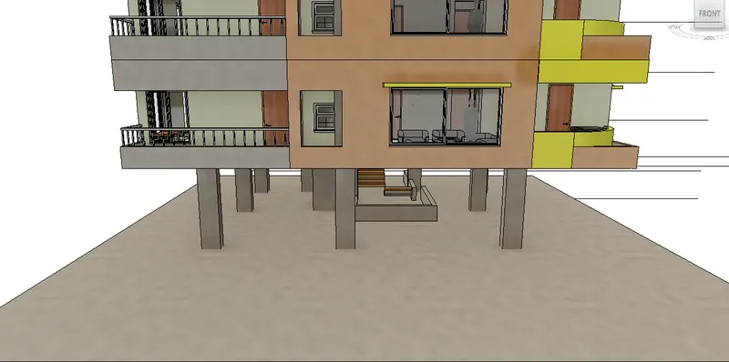
- Curtain wall glazing to be provided in the lobby area
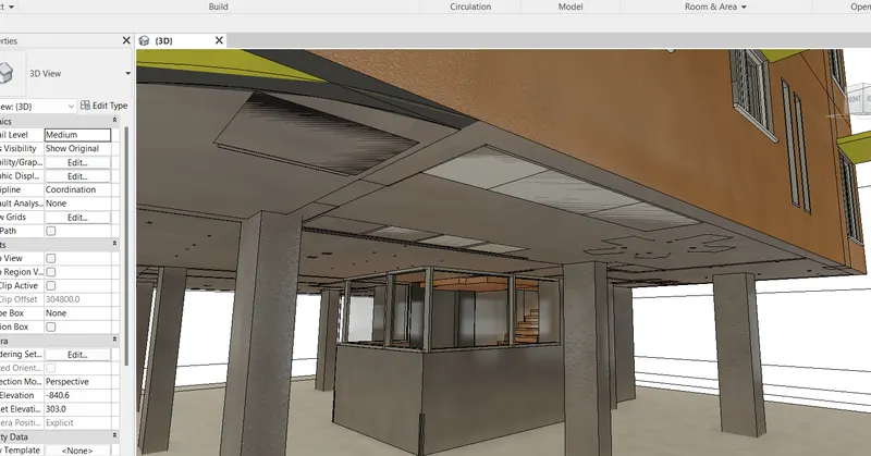
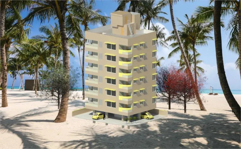
- Various Elevation, Section and 3D views are shown below for reference
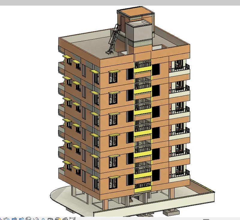
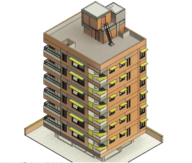
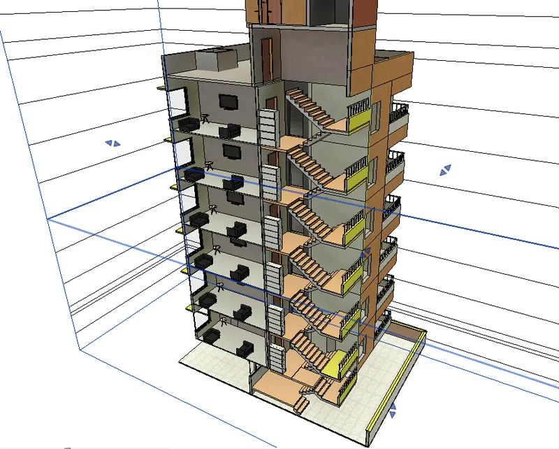
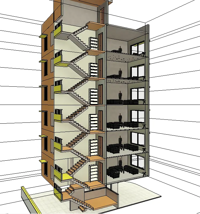
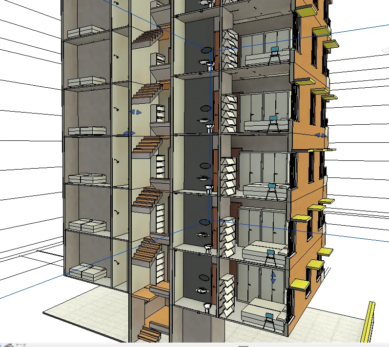
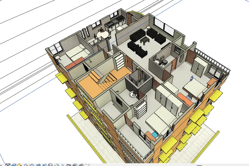
- The rendered view of the building is shown below
5) Provide a set of drawings in an architectural and structural model to list the following details with categories and appropriate sheet templates included
a. Floor Plans with Annotations
b. Elevations
c. Sections
Ans 5.
INTRODUCTION: Creating the sheet templates
AIM : To create the sheet templates for Floor plan with annotations, Elevations and sections.
PROCEDURE:
- Provide the Room tag showing Room name and area of the room
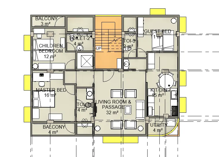
- Create the Sheet templates from View tab for Floor plan , Elevations & Sections
- Provide the project details in the template from Project information
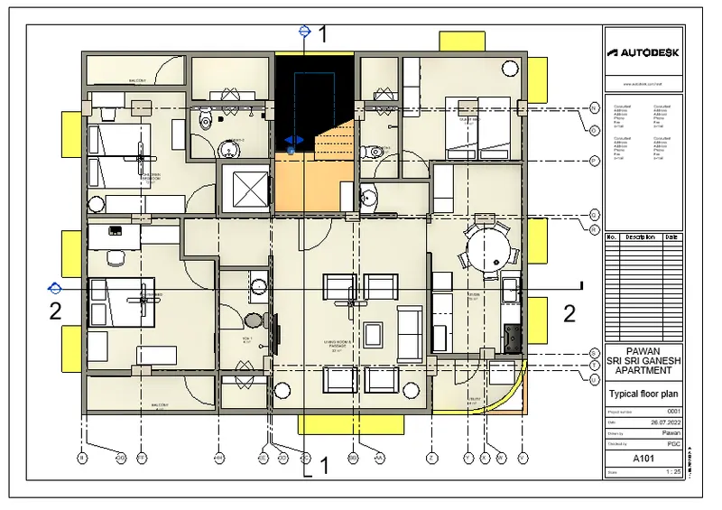
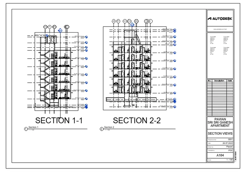
CONCLUSION: Thus we have created the templates for the Floor Plan, Elevations and Sections.
6) Using the Rendering settings, Render images of the 3D model produced and include the rendered images to the drawing sheets
a. Rendering from interior rooms
b. Rendering from out showing topographic features
c. Rendering through structural framing
Ans 6.
NTRODUCTION: Rendering and Creating the sheet templates
AIM : To create the sheet templates for Floor plan with annotations, Elevations and sections.
PROCEDURE:
- Set the camera inside the plan view and project the area to be viewed.
- Check the 3D view and render the view
- Create the template for the rendered views
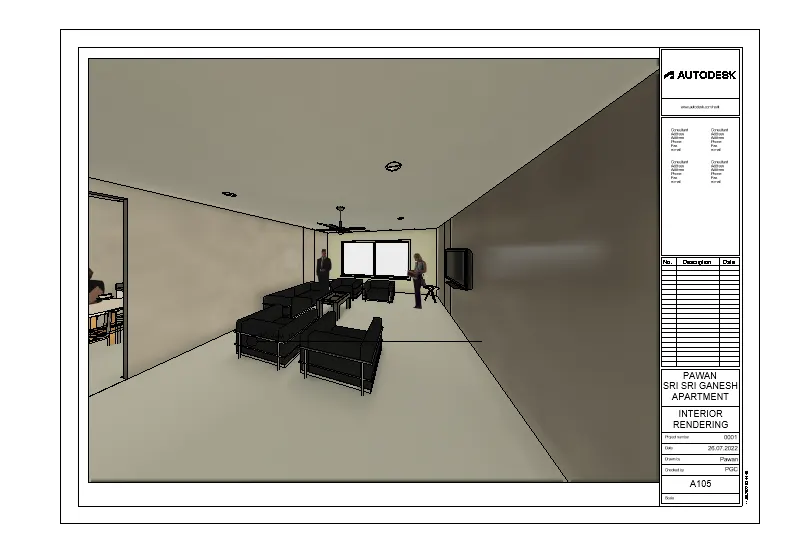
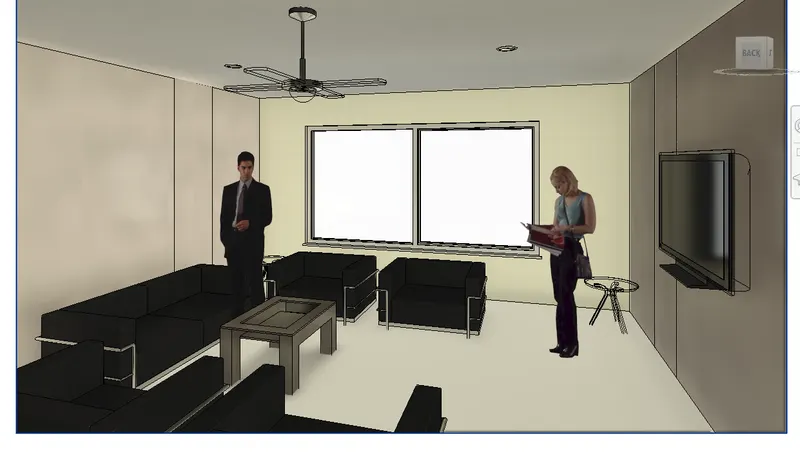
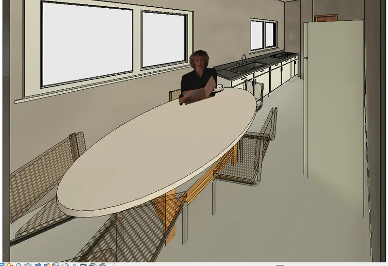
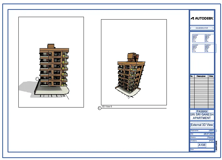
- Create the 3d views for the structural model
CONCLUSION: Thus we have created the 3D views and rendering for the views and also created the templates for rendered views for interior views and external views.
7) Print the set of drawing sheets created and submit the drawings from the architecture and structure model
Ans 7.
INTRODUCTION: Printing the drawing sheets
AIM : To print the drawing sheets created for submission for the architectural and structural model
PROCEDURE:
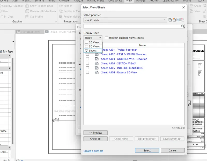
- Select the required sheets from the models created and print the same for submission
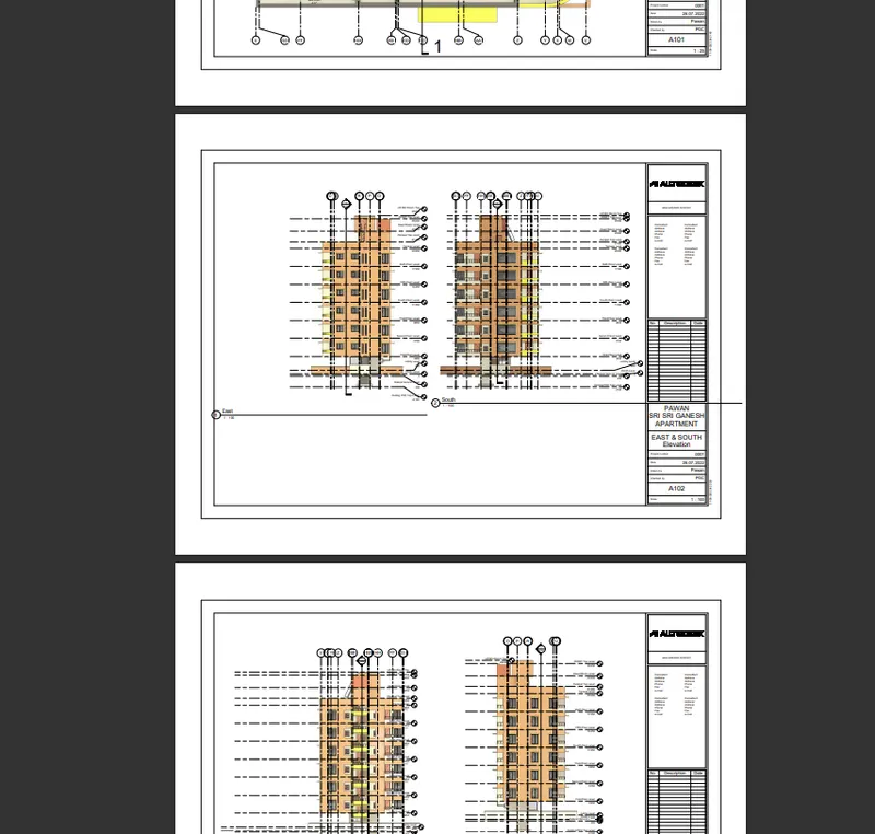
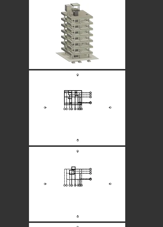
CONCLUSION: Thus we have printed in PDF format, the sheets created in the project for submission.