Creating Architectural and Structural model with 3D rendering using REVIT
1) Select the type of structure you want to build from one of the three below:
a. Multi-Unit Residential Apartment
b. Office Buildings
c. School
A multi-unit residential apartment.
2) Assume reasonable assumptions for geographic and location details for your project modelling. Based on assumptions and type of structure selected identify the modelling requirements from NBC.
The geographical and location details of the project are:
- The building comes under the residential category and it is situated on the outskirt of the city.
- The project is located near the highway.
- The road width in front of my building is 60'.
- The height, area and safety measures will follow the rules and regulations of NBC.
- The height of my project is 42' and the road width is 60'.
- So the building height is 12.8 m and the road width is 18.2 m, the height of the building should not exceed 1.5 times the width of the road width.
- In this case the building height is not exceeding so it is suitable for construction.
3) Using the structural model, include the following components based on the type of structure selected
a. Foundation - Isolated/Wall/Matt Foundation
b. Columns
c. Beams Connected to Columns
d. Roof Framing/Truss
e. Floor / Decks
f. Floor Openings for Elevators and Stairs
AIM
To create the structural model, including the components like foundation, column, and beams connected to column, Roof framing or truss, Floor/Decks, and Floor opening.
INTRODUCTION:
- Beams and columns are two important structural elements that play a key role in creating a safe load path to transfer the weight and forces on a structure to the foundations and into the ground.
- Beams and columns could be built using the same shapes and materials but each serves a different function and is designed differently.
- A foundation is the lowest part of the building structure.
- It is the engineering field of study devoted to the design of those structures, which support other structures, most typically buildings bridges or transportation infrastructure.
- It is at the periphery of Civil, Structural and Geotechnical Engineering disciplines and has a distinct focus on soil-structure interaction
PROCEDURE:
Open Revit - Structural Template.
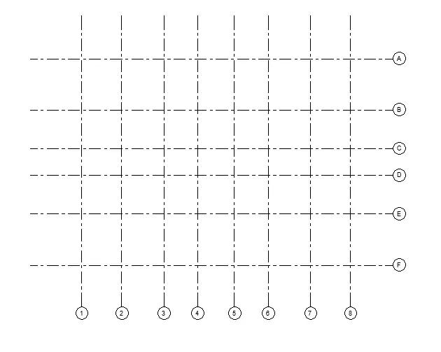
Go to the Architecture> Datum> Grid
Draw the vertical and horizontal grids as shown below.
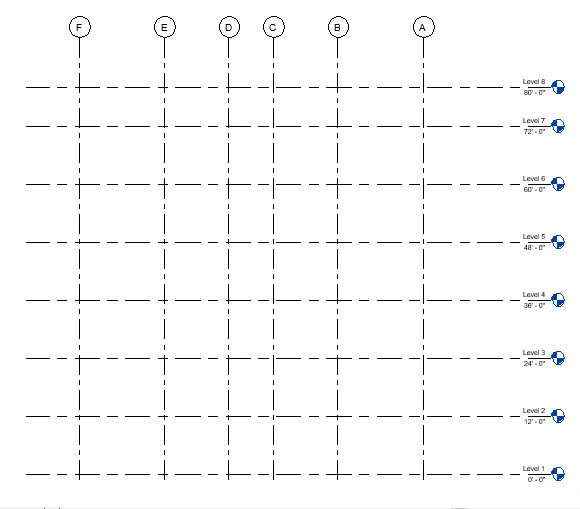
Go to the Architecture> Datum> Level
Create levels as shown in the figure.
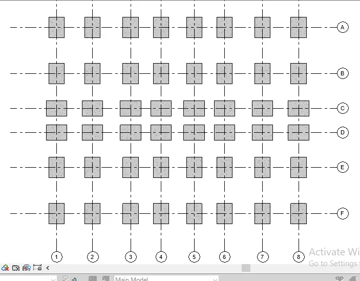
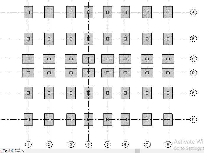
Adding isolated footing at each grid point of size 1800 x 1200 x 450mm and 1200 x 1800 x 450mm.
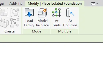
Go to Structure> Foundation> Isolated
Select the appropriate foundation from the list.
Place the foundations "At Grids"
Next, we need to add the columns with the size of 450mm x 600mm and 600mm x 450mm.
Go to Structure>Column
Select the required column from the list.
Place the columns "At Grids"
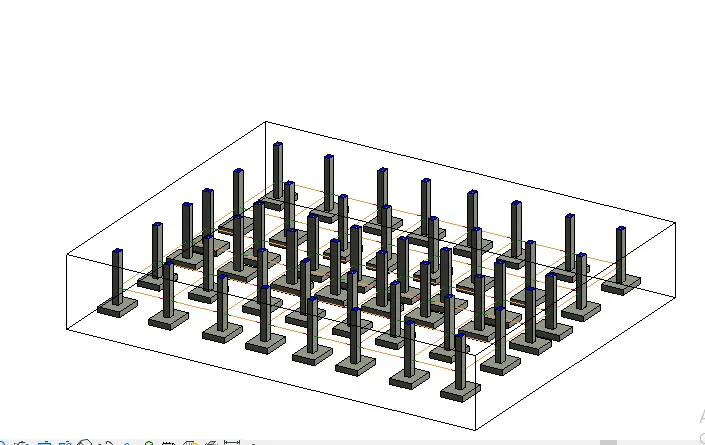
A 3D view of the columns and foundation is shown below
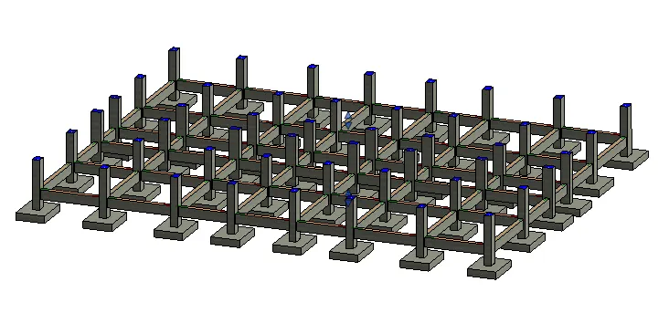
Adding concrete rectangular beams of size 300 x 600mm to the columns
Go to Structure> Beams
Select Concrete rectangular beam 300x600 from the list
Draw the beams at the required positions
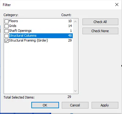
Copy and paste the beams to all the floors
Filter all other elements before copying
Go to Clipboard> Copy to clipboard
Paste> Aligned to selected levels
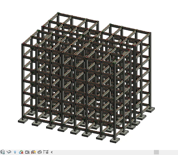
A structural floor is created for each floor
Go to Structure> Floor
Choose Insitu concrete 150mm from the list
Draw the floor as shown below.
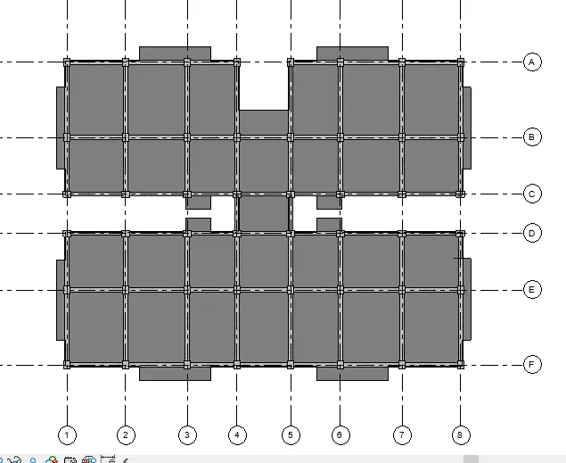
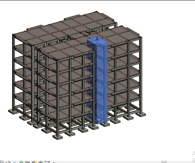
A shaft opening is created for the stairs as shown below
Go to Structure> Shaft
Create the shaft as shown below.
RESULT:
The given components are created successfully using a structural template in Revit.
4) Using the architectural model, include the following components based on the type of structure selected
a. Wall Layout with appropriate material and finishing
b. Exterior façade with fancy finish
c. Interior partition walls to size rooms
d. Components to add details to a room (Desk, Chair, Lighting, Plumbing fixtures)
e. Add components such as stairs Elevators
f. Have at least one side of the building with curtain walls and glass panels
g. Include interior and exterior lighting fixtures
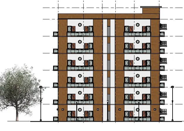
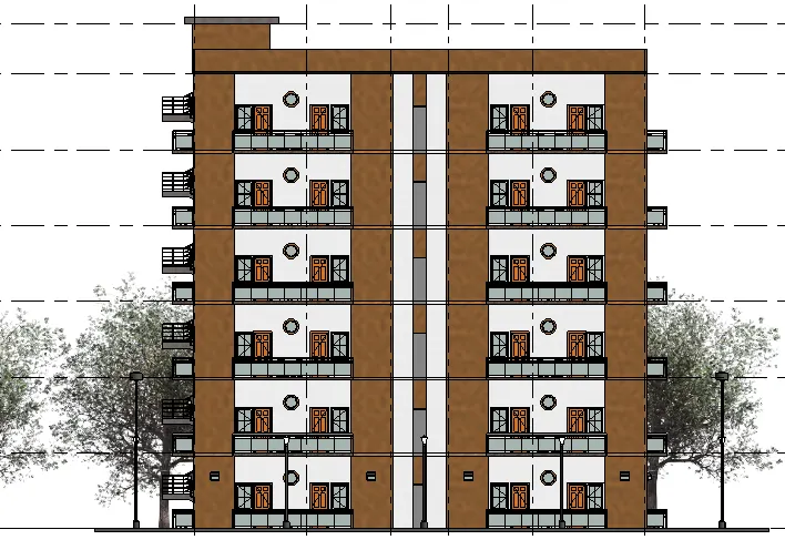
h. Place proper topographic components from outside (Trees, Parking, Plants) to add details to the model
AIM:
To include the given components based on the type of structure selected using the architectural model.
INTRODUCTION
- Partition walls are a significant component of a building design. Without partition walls, a building's plan cannot be decorative or structured
- Lighting fixtures, come in a wide variety of styles for various functions
- The most important functions are as a holder for the light source to provide directed light and to avoid visual glare.
- Some are very plain and functional, while some are pieces of art in themselves
- Nearly any material can be used so long as it can tolerate the excess heat and is in keeping with safety codes.
PROCEDURE
Open Revit - Architectural Template
Link the structural file to the architectural file
Go to Insert> Link Revit
Select the structural file created in the previous question
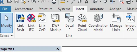
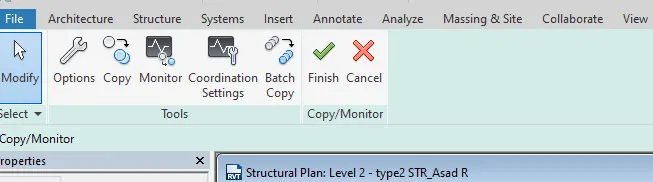
Go to Collaborate> Copy/ Monitor> Select Link
Select the linked file
A new tab will emerge, Click Copy
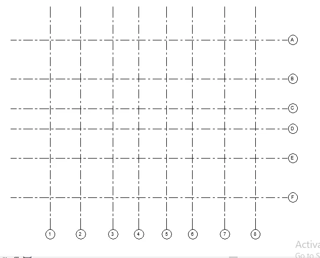
Copy the grids and levels one by one, and Click Finish.
All the grids and levels from the previous file are copied into the new file.
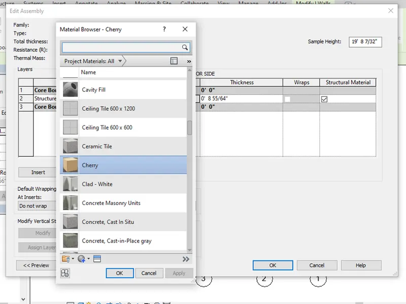
Click on the Wall > Edit Type > Structure > Material Browser
From the material browser, search for the required materials and hit apply.
Follow the same procedure to allocate materials to all your Architectural walls and floors.
a) Wall Layout with appropriate material and finishing:
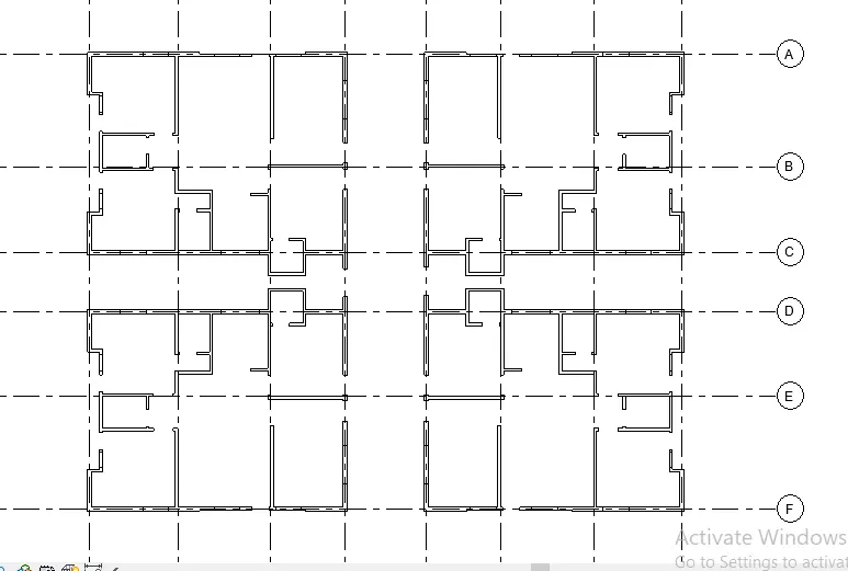
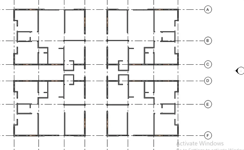
To create the wall layout with appropriate material and finishing, first, we need to draw the layout of our plan
Draw the walls and partition walls as shown below.
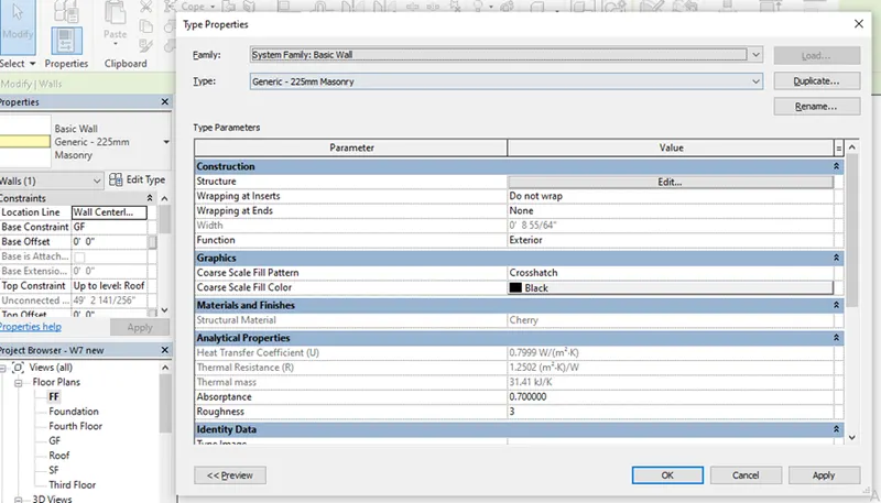
Click on the Wall > Edit Type > Structure > Material Browser
From the material browser, search for the required materials and hit apply.
b) Exterior façade with fancy finish:
After creating the layout we can manage the material of the wall either with the help of the properties option or from the Edit type option as just shown in the below figure:
c) Interior partition walls to size rooms
Choose a different wall for interior partitioning with a thickness of 135mm, we mostly provide a thinner wall for partitioning the inner wall as compared to exterior walls.
d) Add components such as stairs Elevators
Select the Stairs in the Architectural tab
Create stairs at the desired place.
Select the stair model and look for the connect option in the modify panel.
Click on the connect option
Select all the levels you want the stairs to go up to.
Once finished clicking all the levels, hit the finish and complete the stair tower.
e) Components to add details to a room (Desk, Chair, Lighting, Plumbing fixtures)
Add Architectural components and plumbing fixtures into the model
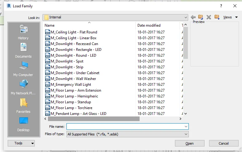
Go to Insert> Load Family
Browse the files and look for the required components by the room dimensions inside the building.
The most common family types include furniture, plumbing fixtures, windows, doors, kitchen appliances, and special equipment.
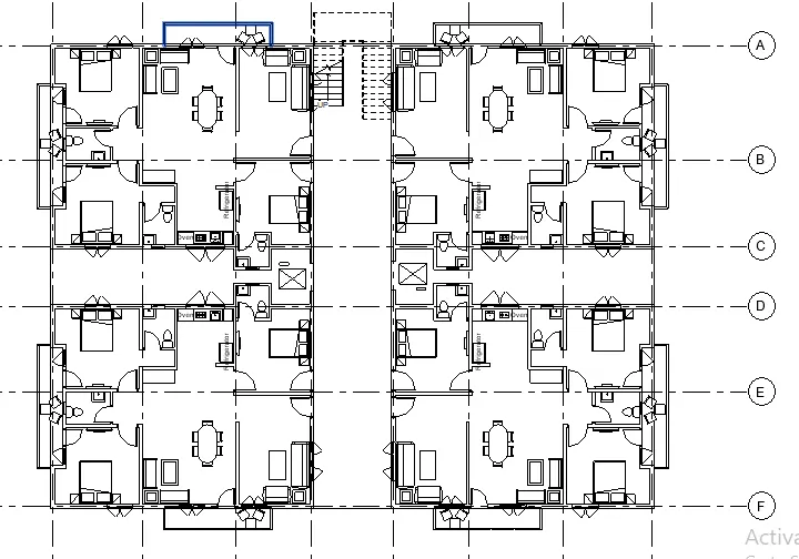
Copy the typical floor plan up to the seventh floor
Select the entire floor plan with all of the Architectural components and plumbing fixtures.
Make sure to filter out the multi-storey stair tower from the selection as it cannot be copied up.
After filtering the selection, copy it to the clipboard.
Then, go to the paste dropdown and choose to align with the selected levels option.
Select all the levels from second to seventh and click OK.
f) Include interior and exterior lighting fixtures
Create a ceiling on that floor to give the light fixture.
Go to Architecture> Ceiling
Create ceilings at the desired places.
After creating the ceiling, add the light fixtures
Go to Architecture> Component
Select the desired light fixtures and place them as shown below.
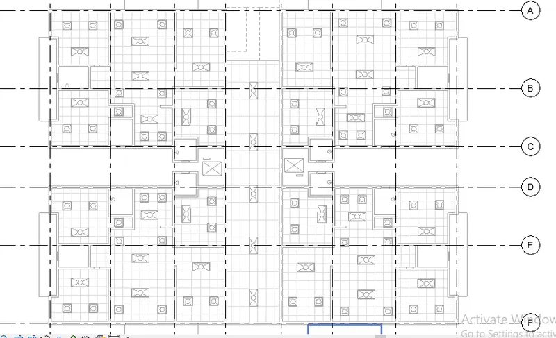
g) Place proper topographic components from outside (Trees, Parking, Plants) to add details to the model
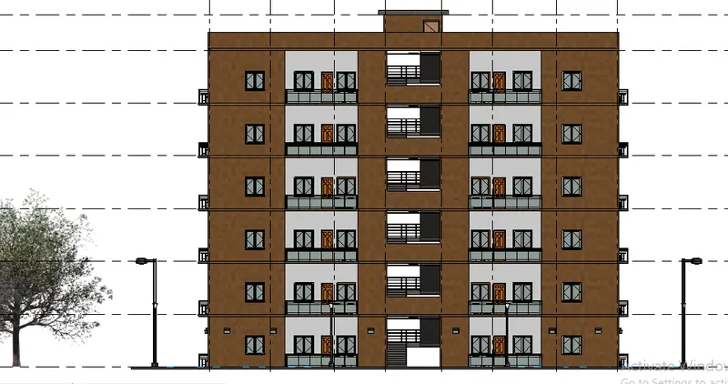
EAST VIEW
WEST VIEW
NORTH VIEW
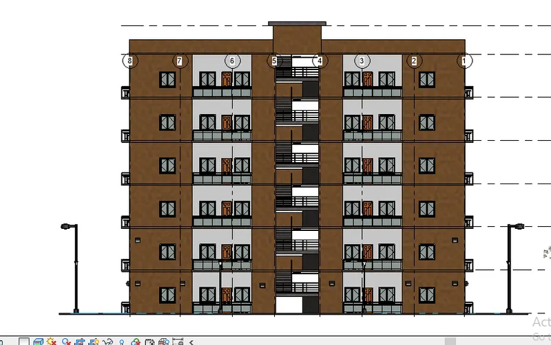
SOUTH VIEW
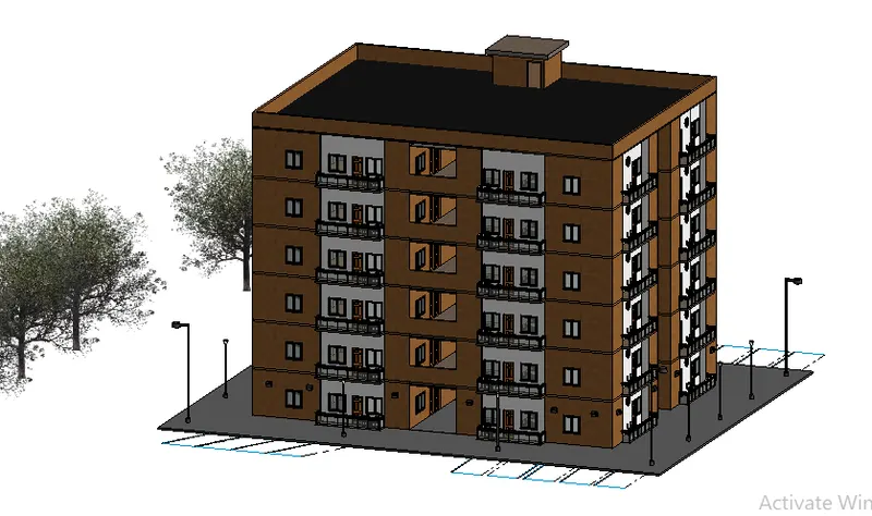
3D VIEW
5) Provide a set of drawings in an architectural and structural model to list the following details with categories and appropriate sheet templates included
a. Floor Plans with Annotations
b. Elevations
c. Sections
AIM
To provide a set of drawings in an architectural and structural model to list the given details with categories and appropriate sheets Templates included
INTRODUCTION
- Floor plans are the most critical element of your house plans Drawn to scale and shown from above floor plans illustrate how rooms. spaces and physical features work with each other within the home
- They're the key documents that show how people will move through the space and interact with their home Floor plans, show the extent to which space will work for its intended purpose
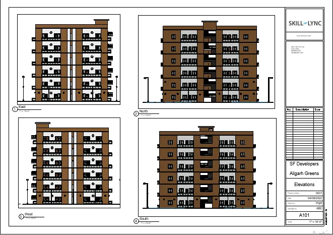
- Al elevation is a view of a building seen from one side, a representation of one view This is the most common view used to describe the external appearance of a building
- Each elevation is labelled with the compass direction it Faces e.g. looking toward the north you would be seeing the southern elevation of the building
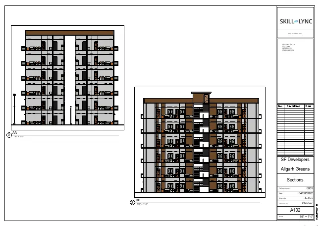
- Sectional views, reveal hidden details in a mechanical drawing These views assume that a cutting plane of the object represented by the drawing displaying the appropriate section of the interior
PROCEDURE
Go to View> Sheet Composition> Sheet
Select the sheet size and parameters.
Drag and drop the views into the sheets.
Building Elevations Sheet
Sections Sheet
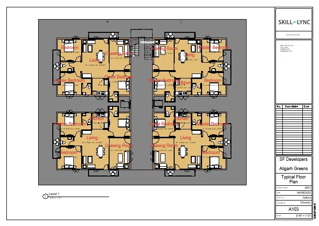
Typical Floor Plan Sheet
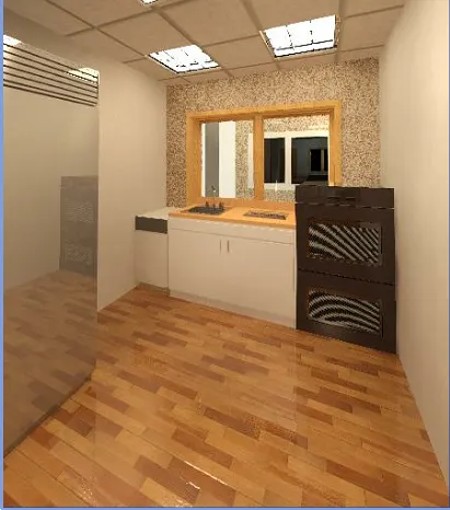
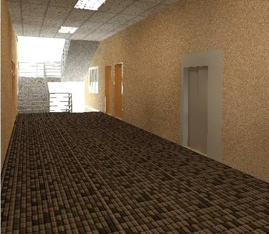
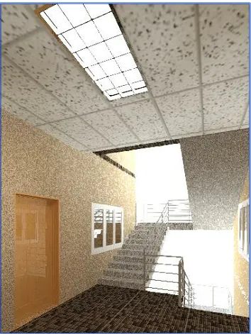
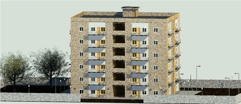
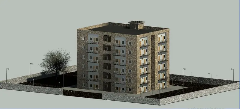
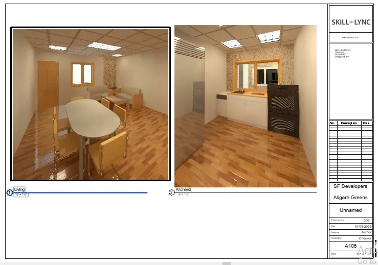
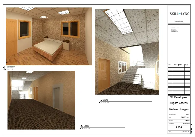
6) Using the Rendering settings, Render images of the 3D model produced and include the rendered images in the drawing sheets
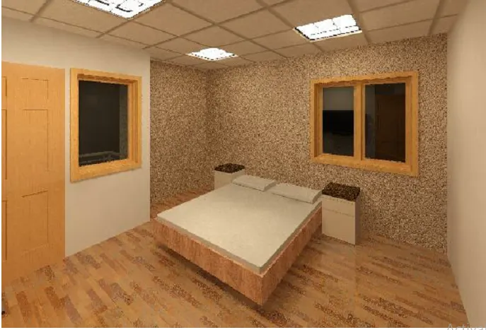
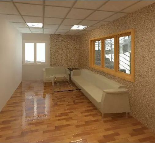
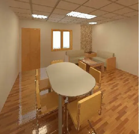
a. Rendering from interior rooms
b. Rendering from out showing topographic features
c. Rendering through structural framing
AIM
To render images of the 3D model produced and to include the rendered images in the drawing sheets using the rendering settings
INTRODUCTION
- Render the view to create a photorealistic image of the 3D model
- After preparing the 3D view and using the Rendering dialogue to select desired settings, click Render to render the age
- Revit begins the rendering process rendering the entire image progressively. Revit displays a progress dialogue, which allows information about the rendering process.
PROCEDURE
7) Print the set of drawing sheets created and submit the drawings from the architecture and structure model
AIM
To print the set of drawing sheets created and to submit the drawings from the architecture and structure model
PROCEDURE
Press CTRL+P
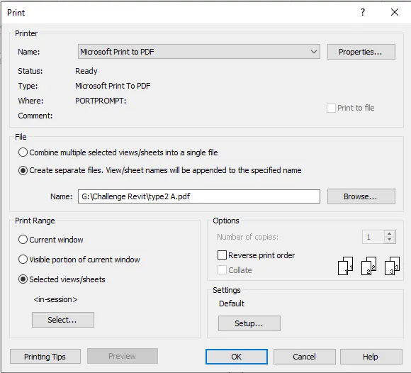
Specify the window, sheets or views to be printed.
Select the sheets to print
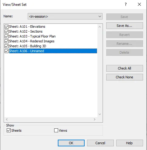
All sheets will be printed if a printer is attached to the computer.
Otherwise, all the sheets will be saved as PDFs.
CONCLUSION
Revit is very efficient when it comes to Building Information Modelling. We can create the Architectural and Structural framework of the project in a reasonable. Everything from 2D floor plans to 3D elevations can be created and stored inside a Revit project. And the same drawings can also be printed on the sheets with relevant parameters. Thus, we created a G+7 Residential apartment building following the NBC norms as well as area and height restrictions with regard to our project location.