Creating Architectural and Structural model with 3D rendering using REVIT
A1) School is the structure I would like to build.
A2) Assuming that the school structure will be located at a region of moderate rainfall, chill , greenery and hilly region and cosist of laterite soil.
Modelling requirements of school structure as per NBC is as follow.
- Clause 12.1.1 page no 29- The height of the plinth shall not be less than 450mm.
- Clause 12.2.1.1 page no 30- The ceiling height shall be 3.6m for all regions and in cold regions 3m.
- Clause 12.2.2 page no 30- The size of habitable room shall not be less than 9.5m2 where there is only single room with a min width of 2.4m. Where there are 2 rooms, one of these shall not be less than 9.5m2 and the other not less than 7.5m2 with a min width of 2.1m.
- Clause 12.4.1 page no 30- The height of a bathroom or water-closet shall not be less than 2.1m.
- Clause 12.4.2 page no 30- Area of the bathroom shall have min 1.8m2 with min 1.2m width and Water closet shall be min 1.1m2 with min 0.9m width. Both combine shall have min 2.8m2 area with 1.2m width.
- Clause 12.4.3page no 30- In a bathroom or WC at least one wall shall open to external air. Not directly over or under any room other than another WC, washing place, bathroom with water tight area. Sloping towards the drain. Having window and ventilator opening towards the shaft.
- Clause 12.5.1 page no 31- Height of the head room shall be min 2.2m.
- Clause 12.7.1 page no 31- Height of the store room shall be min 2.2m.
- Clause 12.18.1.1 page no 34- The width of the staircase shall be min 1.5m.
- Clause 12.18.1.2 page no 34- The width of the tread shall be min 300mm without nosing.
- Clause 12.18.1.3 page no 34- The width of the riser shall be min 150 mm and shall be limited to 12 per flight.
Fire and life safety
- Clause 3.3.2 Table 2page no 15- Considering using Light weight concrete block without finish and non load bearing the min thickness of the block shall be 150mm to restrain fire for 4 hr for half hour min width is 90mm.
- Clause 6.2.4.2 page no 51: Everyroom with more than 45 students must have min 2 doors.
A3) Aim: To create a structural model for the school structure.
Introduction: For a non load bearing structure a frame structural model is required to hold the building strong where all the loads of the elements will be transmitted through slab - beam - column - footing and then to the ground. To avoid deformation of the structure SBC of the soil will analysed and the footing will be placed at that level of good SBC. Revit helps us to have a better visualisation of the structure by creating it accordingly to architectural structure.
Procedure:
Initial procedure
- I have opened the structural template as explained in the challenge 06 and created a grid line to position the column and updated the project information as shown in Fig A7.
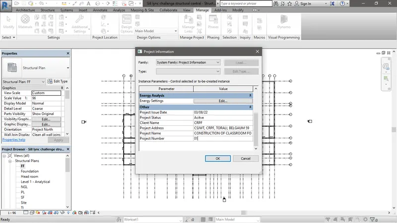
Fig A7
To place column
- Now click to column in structure tab and choose the desired column in properties browser as shown in Fig B7 and place it at a required position.
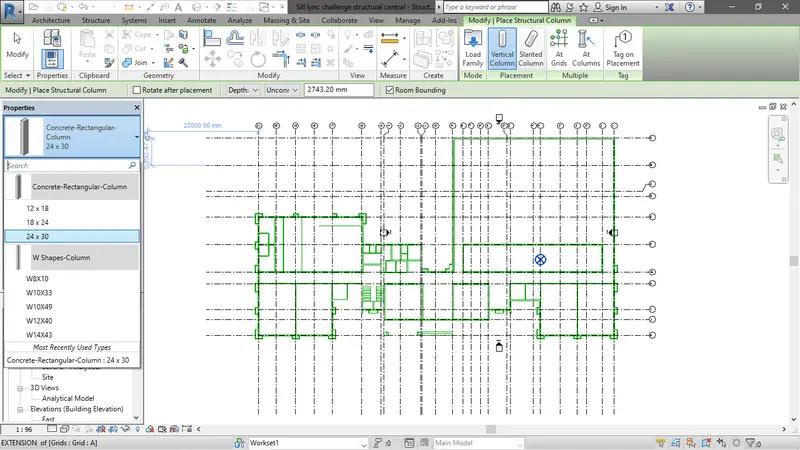
Fig B7
- Hence fig C7 shows the complete position of the column of the structure by adjusting the top base and bottom base to the required level ok property browser.
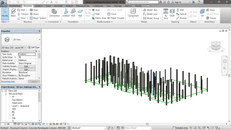
Fig C7
To place footings
- Now to place footing for each column first go to the foundation level of the structure and then go to isolated footing in the foundation panel of the structure tab as shown in fig D7
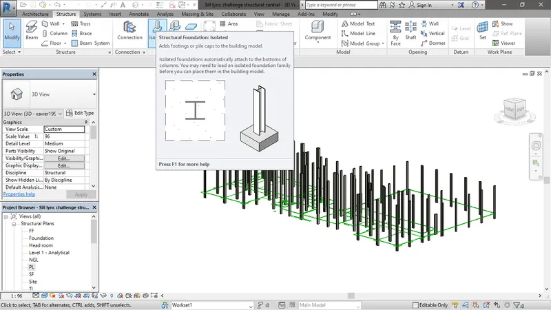
Fig D7
- Select At columns in Multiple pan of modify place isolated tab as shown in Fig E7
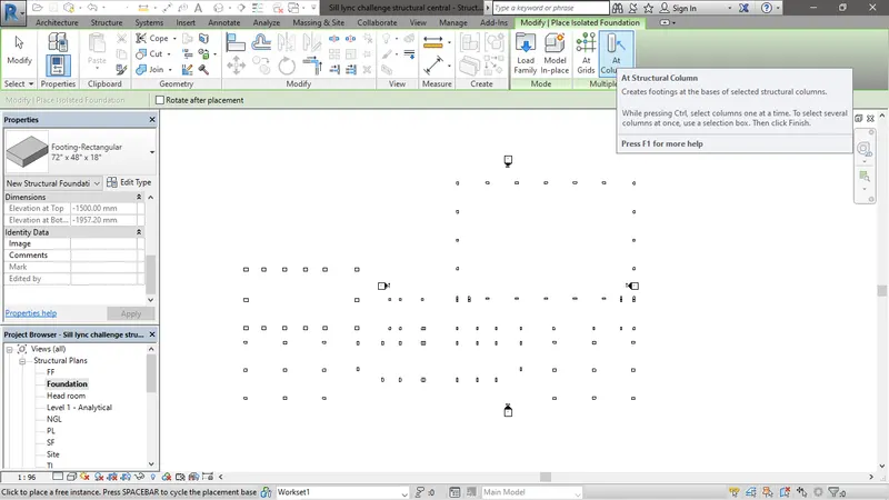
Fig E7
- Now select all the columns to place the footings as shown in fig F7 and then click on finish.
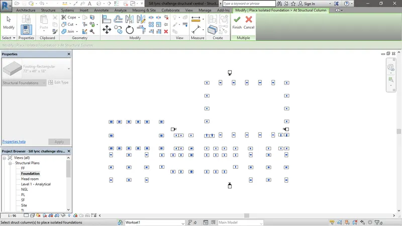
Fig E7
- Foundation is now placed under each colum as shown in fig G7.
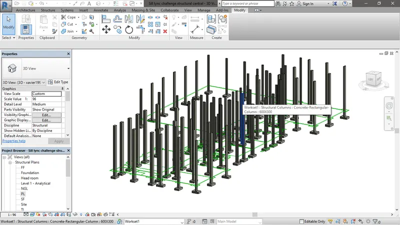
Fig G7
To place beams
- Now to connect columns with a beam go to Beam in structure tab and choose the required beam in the properties and place it between columns positioned where required. As shown in fig H7.
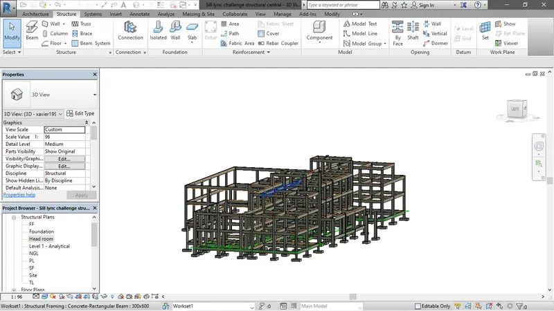
Fig H7.
To place truss
- Now for truss go to truss in structure tab as shown in fig I7.
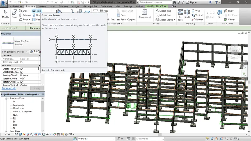
Fig I7.
- Selecting type of truss required from the family and altering as per the requirement the truss is placed to the desire position as shown in fig J7.
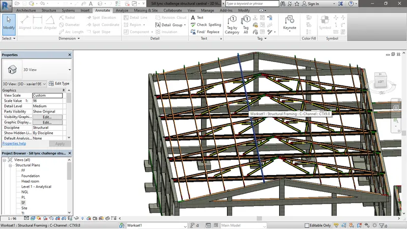
Fig J7.
To place floor, roofs or decks.
- Go to structure tab > floor drop down box> Floor: structural as shown in fig K7.
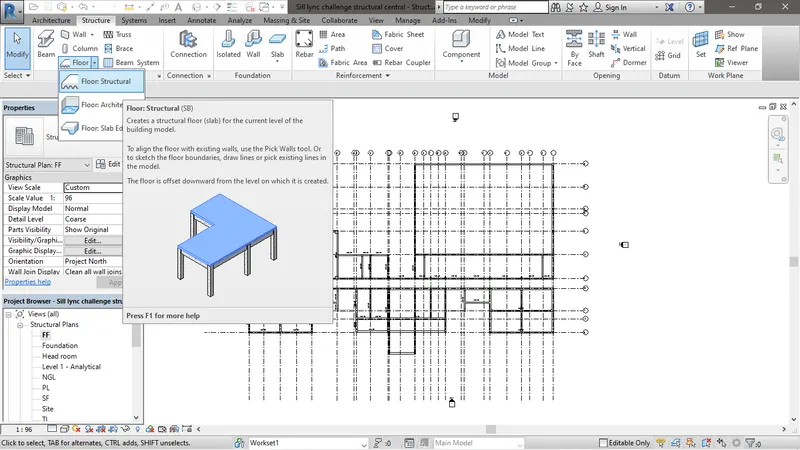
Fig K7.
- With the help of drawing tool draw the floor line as shown in fig L7
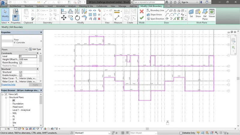
Fig L7
- Fig M7 show floor placed at First floor of the structure.
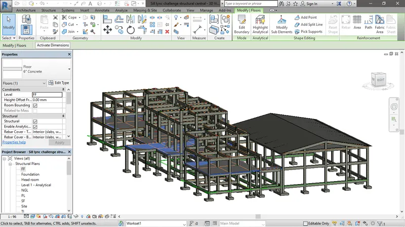
Fig M7
- To place the floor in the rest floor select the floor and then go to copy to clipboard in modify tab as shown in fig N7.
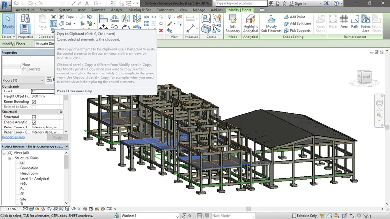
Fig N7.
- Now click on paste drop down box > Aligned to selected level as shown in fig O7.
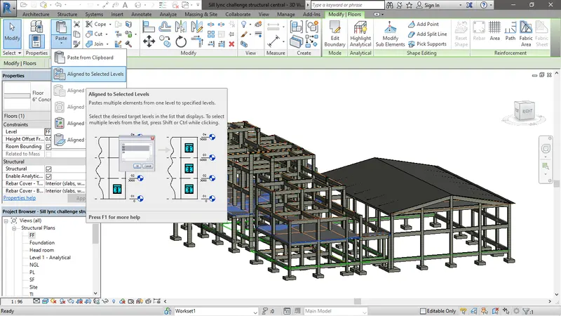
Fig O7
- Select the level in the dialog box and click ok as shown in fig P7.
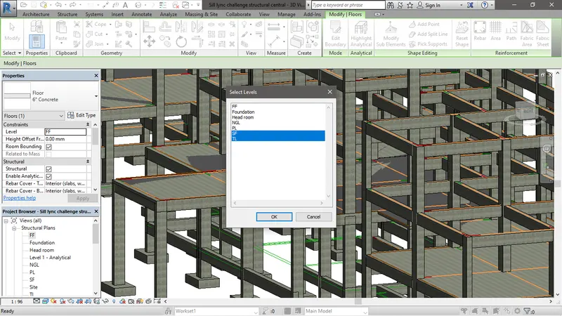
Fig P7.
- Fig Q7 shows the floor pasted to required level.
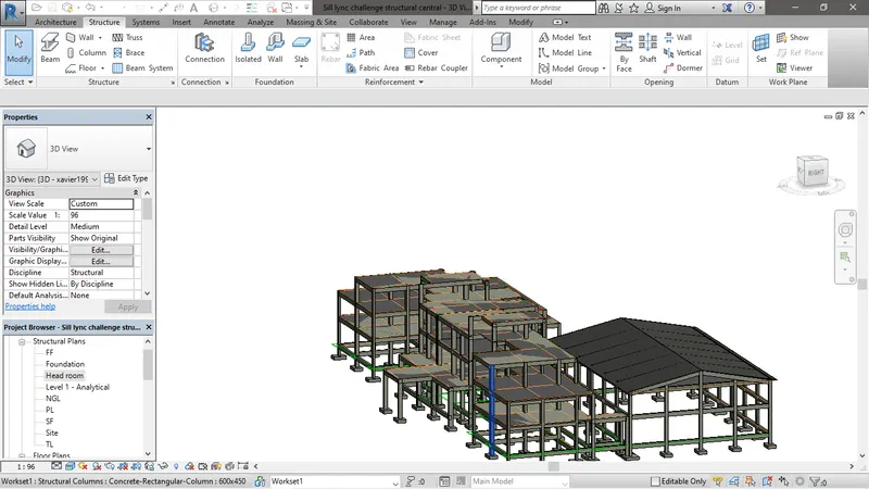
Fig Q7
To create opening for staircase.
- Go to structure tab > shaft opening in opening panel as shown in fig R7.
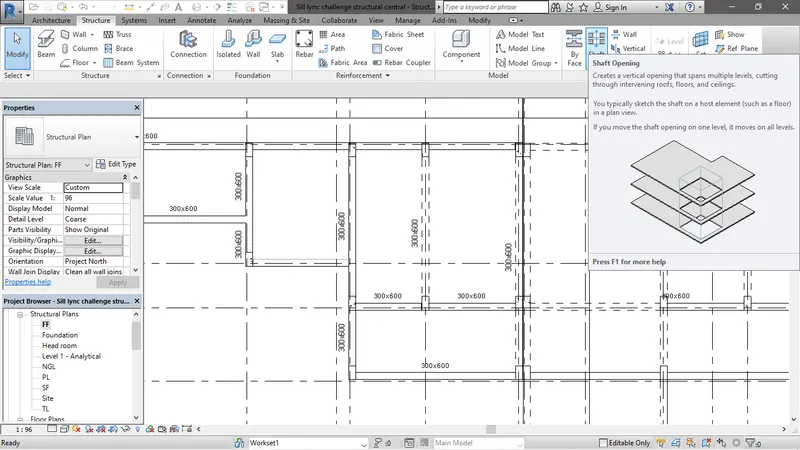
Fig R7.
- Draw the closed line to create a shaft keeping top constrain upto TL in properties browser and base constrain FF and click on finish. AS shown in fig S7.
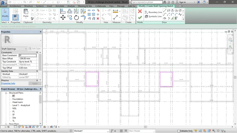
Fig S7.
- Fig T7 shows the opening done in the shaft.
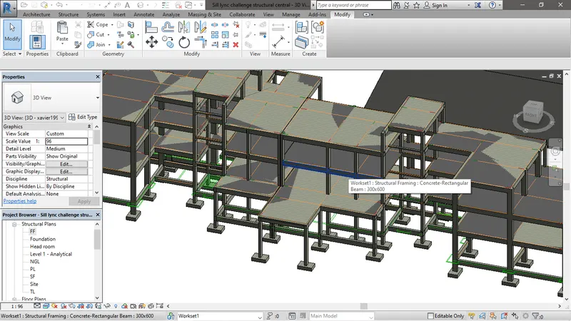
Fig T7
A4) Aim: To create Architectural model in the linked structural model like walls, doors and other basic components.
Introduction: For construction of any structure a concept of architectural model is required in advance to understand the functional and have a better visualisation of the the structure. Now linking the structural model to this file an architectural component will be placed as explained in the following procedure.
Procedure:
To place wall, doors, partition walls , windows and other components.
- Place the all the architectural component as explained in earlier challenges as shown in fig U7
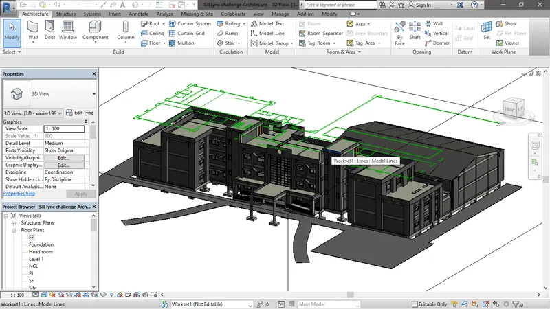
Fig U7
- To create a staircase go to Architecture tab > Circulation panel> Stair. Now go to Modify| create stair > Run as shown in fig V7.
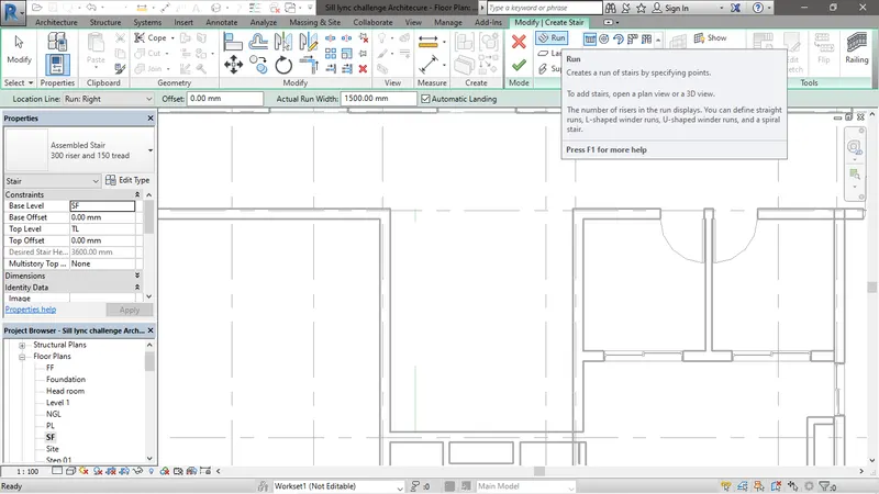
Fig V7.
- In properties browser alter the stair respective to the requirements and setting the Base level to PL and Multistory top to TL.
- Now run the Stair to create a stair as shown in Fig W7 and fig X7 shows the created stairs in the model.
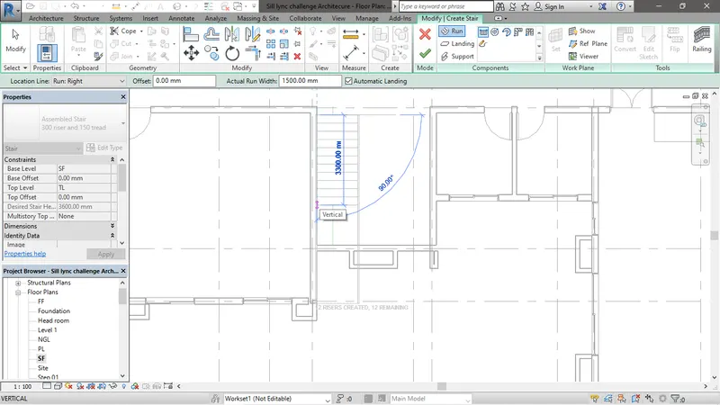
Fig W7
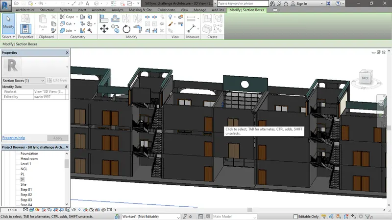
Fig X7
- To create a topography go to Massing and site tab > Toposurface. Now place the point with suitable level and click finish. To place parking component go to Massing and site tab > Parking component and select the component and place it at the required position as shown in fig Y7.
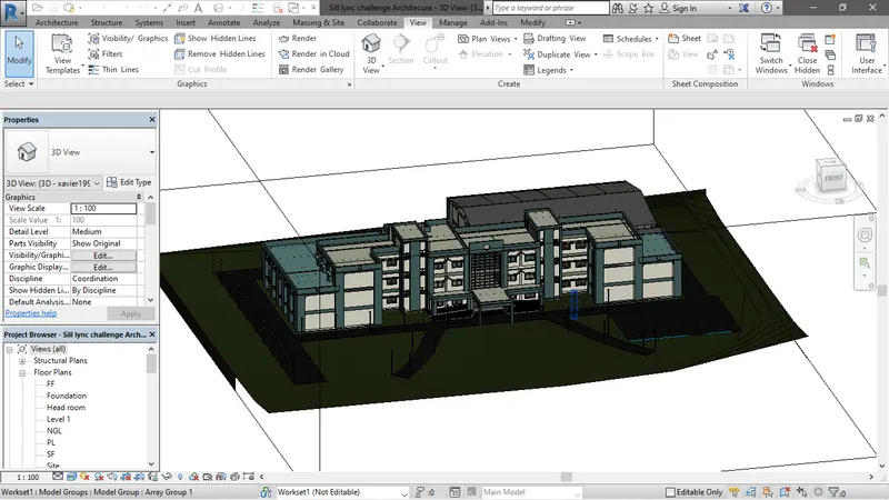
Fig Y7.
A5) Aim: To create a set of drawing displaying floor plans and elevations of architectural and structural model with annotation.
Introduction: To present the drawing on the site the models are placed in the sheet and the print of it is taken with details.
Procedure: The procedure to create a drawing sheet is being explained in the previous challenge. Following are the image of the drawing sheet.
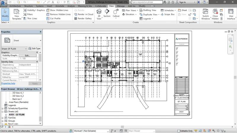
Fig. Plan sheet
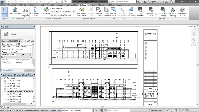
Fig. Elevation sheet
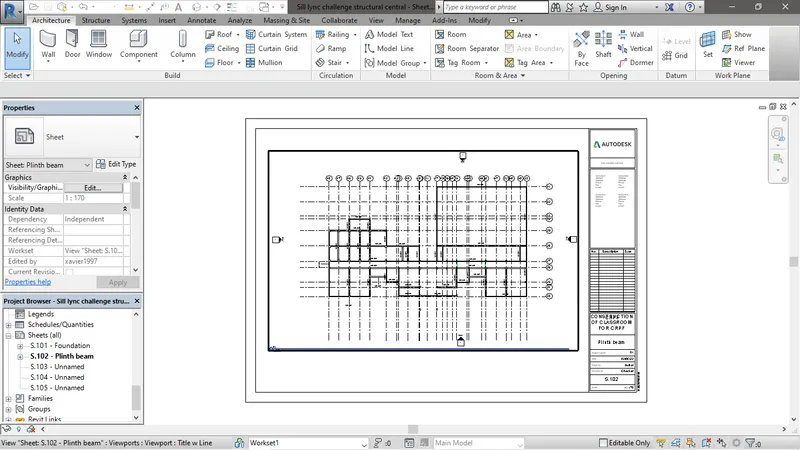
Fig. Structural sheet
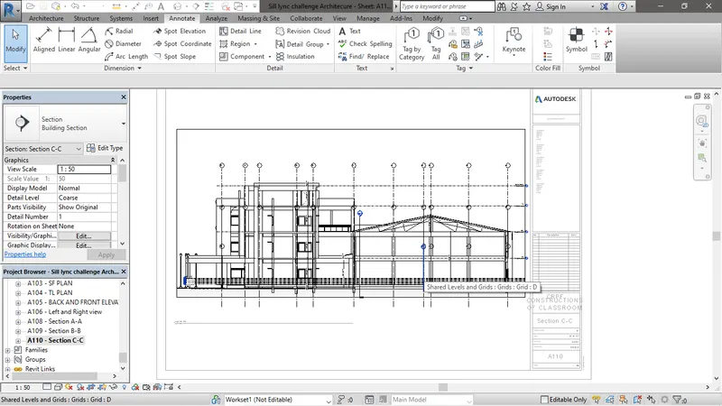
Fig. Sectional sheet
A6) Aim: To render the model and include in the drawing sheet.
Introduction: After creating the model, to have a better understanding of the model like in the real time, render is the tools which is used to create a real time view of the model.
Procedure:
- To render out showing topographic view first go to the level you want to view the model.
- Go to View tab > Create panel > 3D View > Camera.
- Now place the camera to the position of the view we require out side the building and adjust the view as shown in below figure.
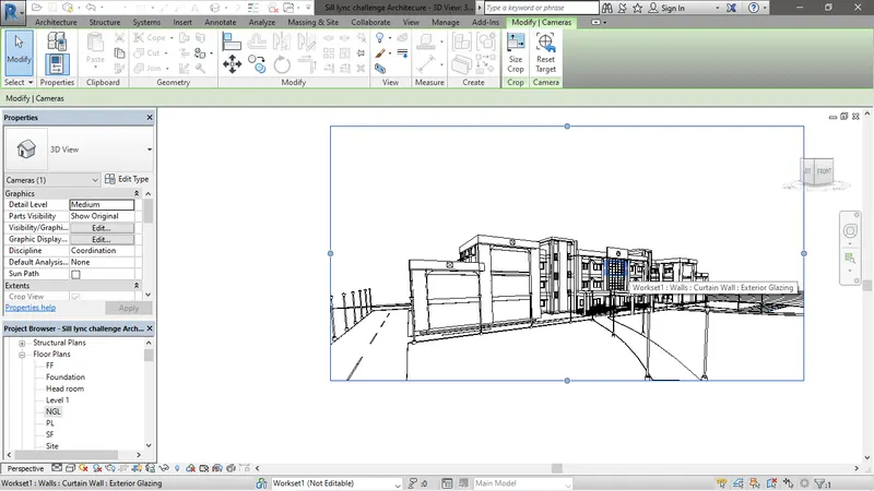
Fig. Camera adjustment for rendering.
- Now again go to View tab > Graphic panel > Render. Now set the settings in the rendering dialogbox and click on render as shown in below figure.
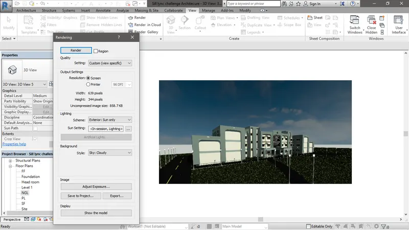
Fig. Rendered image.
- Now click on Save to project and name the rendering and click oK as shown in following fig.
- Now include this render to drawing sheet.
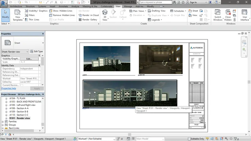
Fig. Rendered image included in sheet
A7) Aim: To print the drawing in pdf.
Introduction: To have the drawing in physical form we can print it out with different sizes and exey the plan accordingly.
Procedure.
- As all the plan, views etc are included in the drawing sheets. This sheet can be printed by going to Revit file > print and set the settings of the print as required and click on print.
- Please check the attachment of the PDF file of the drawing sheet.