Creating Architectural and Structural model with 3D rendering using REVIT
1. Aim: To design the Multi story residential building.
Introduction: To design the Multi story residential building.
Procedure:
- Here i am choosing to design a residential building in Architectural and Structural model.
- First we need to open the revit software and select for the Architectural template.
- Then click on the Open tab and select the template.
-
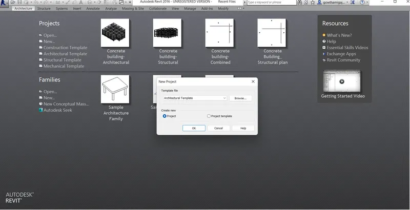
- Then the architectural template will open.
- And then go to the Architecture tab and select Grid command.
-
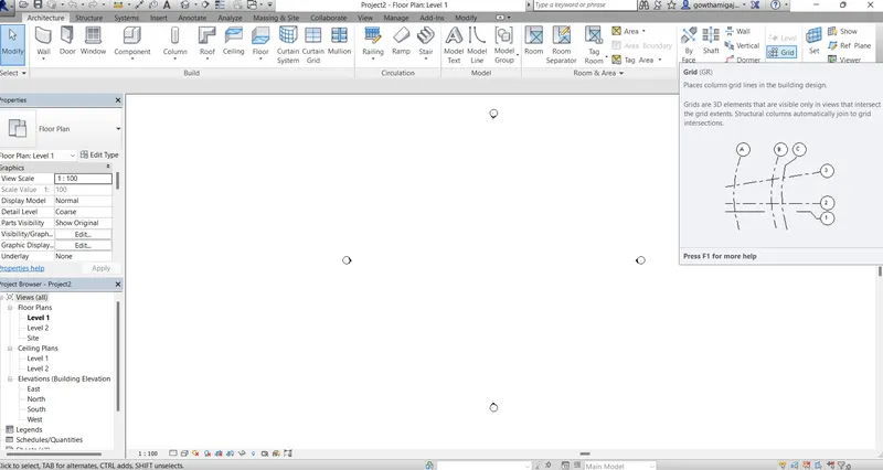
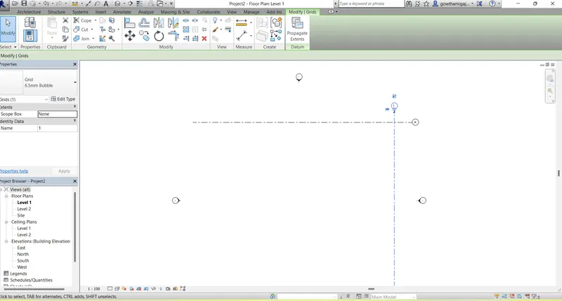
- Then draw the grid in the longitudinal direction as vertically and transverse direction as horizantally.
-
- Then go to Manage tab and select the coordinates command.
- Select the option as Specify coordinates at point option.
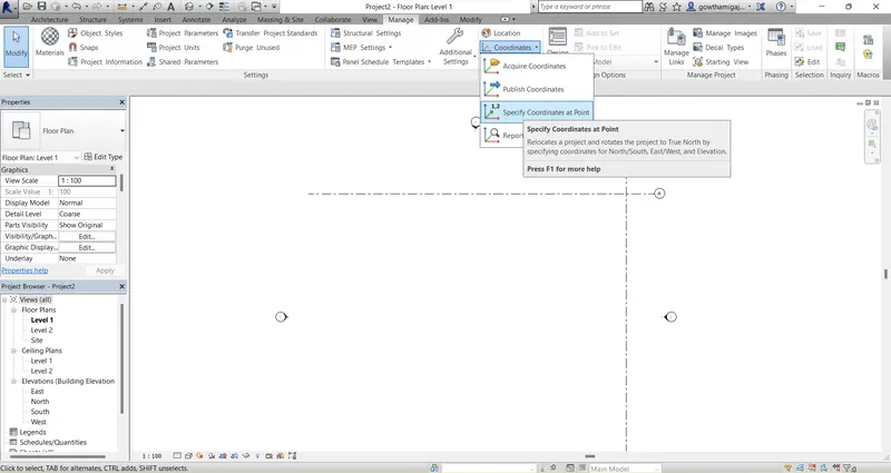
- Then the dialogue box will get open.
- Then give the cordinates for North South direction and select the the grid line.
- In the same way give the coordinates for both longitudinal and transverse grid lines.
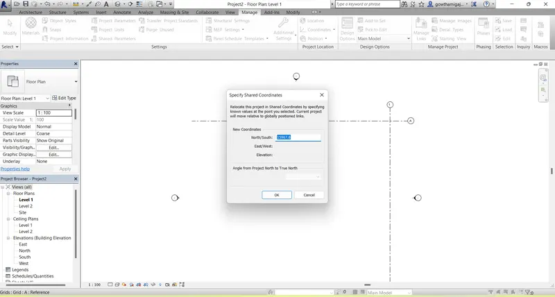
- Then clic OK.
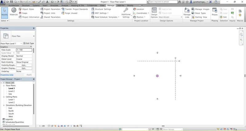
- Open the revit software and click on new file
- Then you will get a dialogue box.
- From that select structural template.
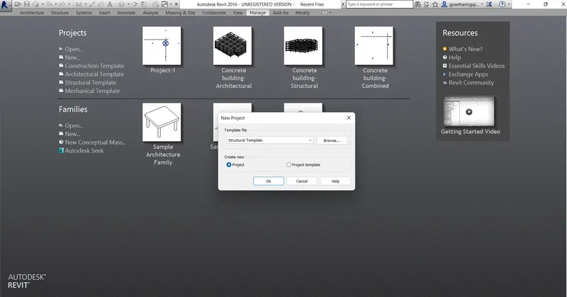
- Now the structural template file is opened.
- Now go to the Architectural tab and select grid command.
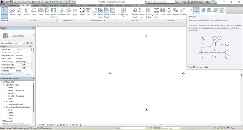
- Then draw the grid in the longitudinal direction as vertically and transverse direction as horizantally.
- Then go to Manage tab and select the coordinates command.
- Select the option as Specify coordinates at point option.
- Then the dialogue box will get open.
- Then give the cordinates for North South direction and select the the grid line.
- In the same way give the coordinates for both longitudinal and transverse grid lines.
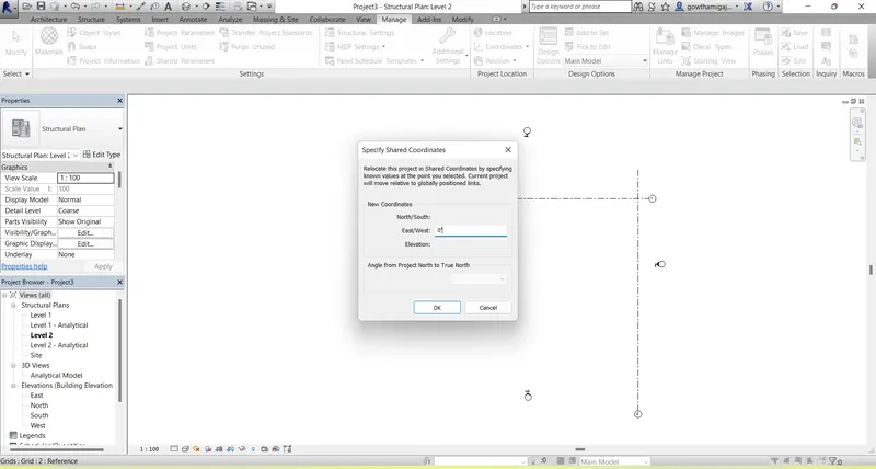
- Then Click Ok in the dialogue box.
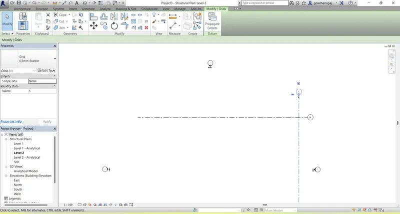
- Now we have to combine both Architectural and structural drawings in one sheet .
- For that, Open the revit software and select the template.
- Then click on the open tool bar and select the file from where it is saved.
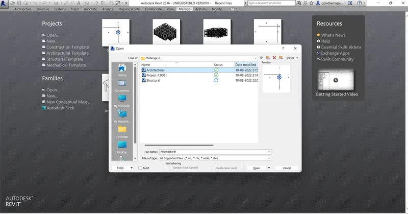
- Now go to collaborate tab.
- Select the collaborate model and save the file.
- Now make the file as collaborate file .
- Then save the file in the central model and you will get a dialogue box regarding saving the file in the central file.
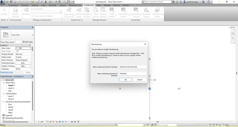
- After the dialogue box, click Ok
- Then the file is saved in Central model.
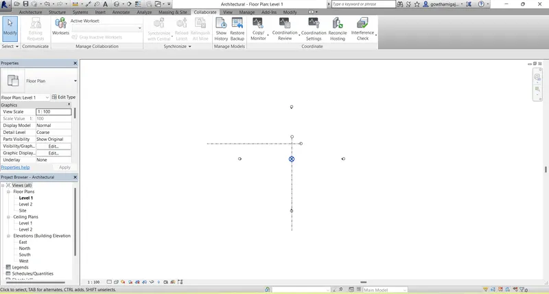
- Then go to the collaborate tab.
- And select the Synchronize option for the drawing.
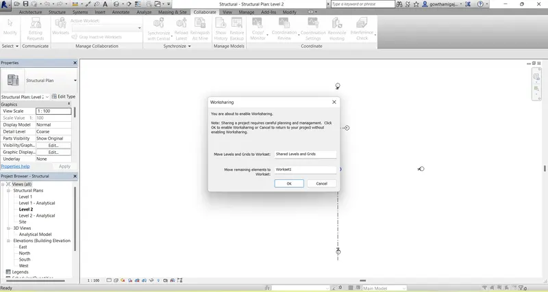
- Now save the file.
- Then a dialogue box will appear on the screen.
- Then click OK.
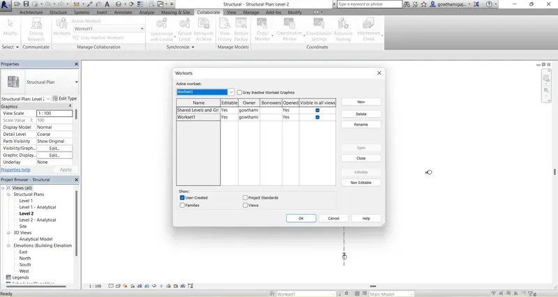
- Now we will get a dialogue box asking regarding about to save the file in the central file.
- Then click on Yes.
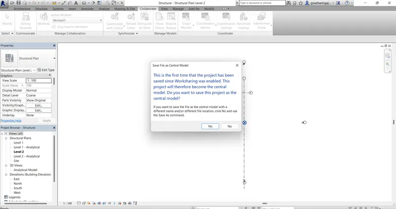
- Then Click on Yes.
- Now the file is combined and saved.
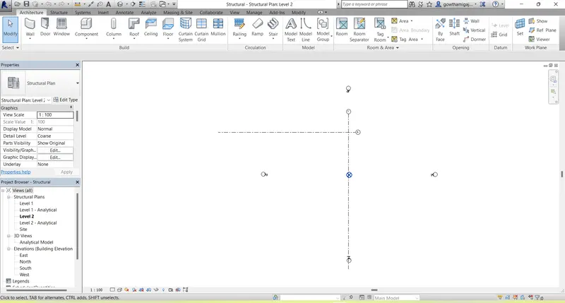
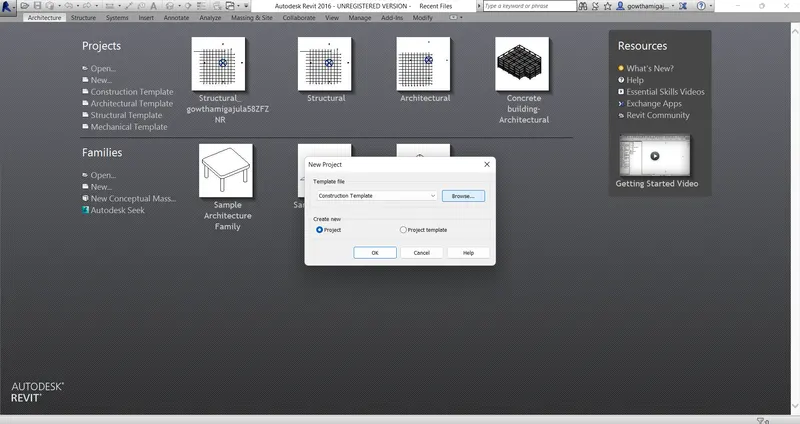
- Now in this drawing we have to take construction template.
- And click OK.
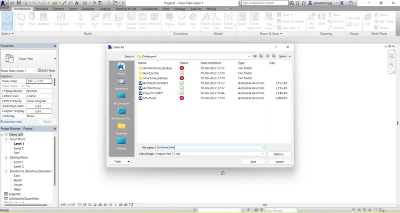
- After opening the construction template file, now save the file in a combined plan.
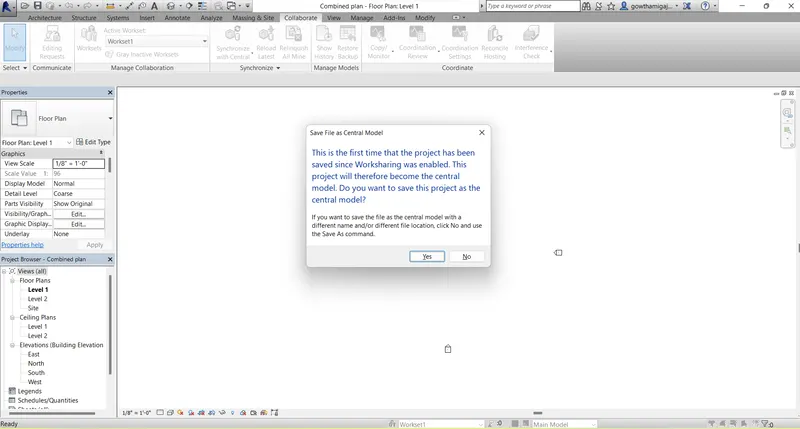
- Now click yes to save the file in the collaborate central model.
- Now open the Architectural file which we have worked previously.
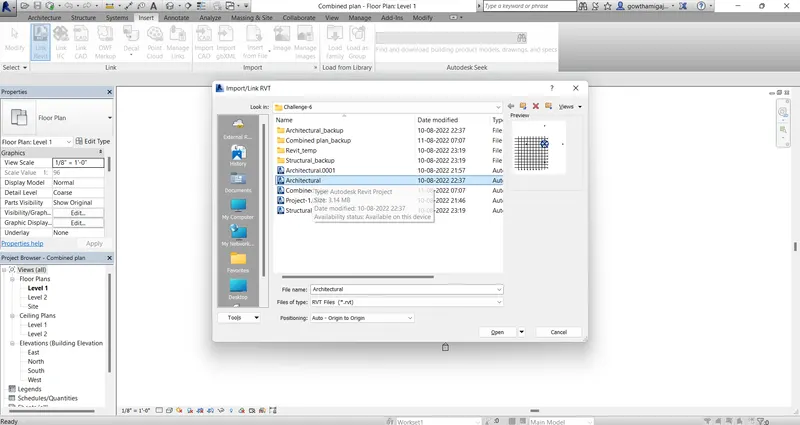
- And also open the structural file in which we have worked previously.
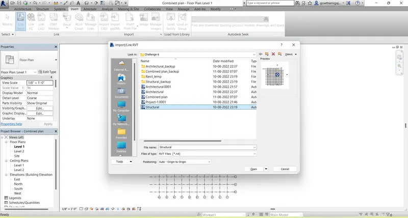
- Now we can see the both architectural and structural drawings which we have worked previously.
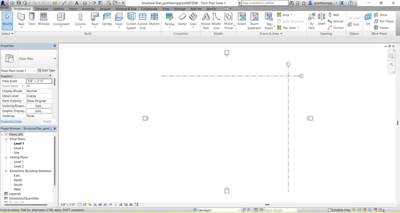
- Now we have to draw the Architectural plan for the above drawing sheet.
- To create residential building, we have to open the revit page by choosing templete.
-
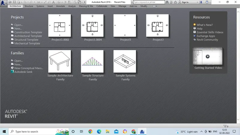
- After selecting the template, the page will get open.
- Then from the architecture tab, take the wall option and draw the wall by taking rectangle or line option.
- Then divide to the rooms by using wall command.
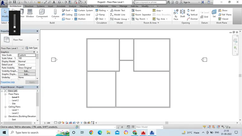
- After completing the rooms, then we have to place the doors and windows.
- For placing the doors and windows we have to select form the load families.
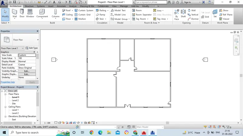
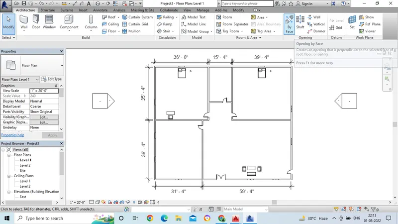
- In this drawing, we have to add the furniture to the house.
- Take the component command, in that we have to select place the component
- Then click on load families.
- From the load families, we have to choose the furniture which is suitable for tha house.
- Now in this drawing we have to insert the furniture bed in bed room.
- Select the bed from the load families and insert the bed in the bed room position.
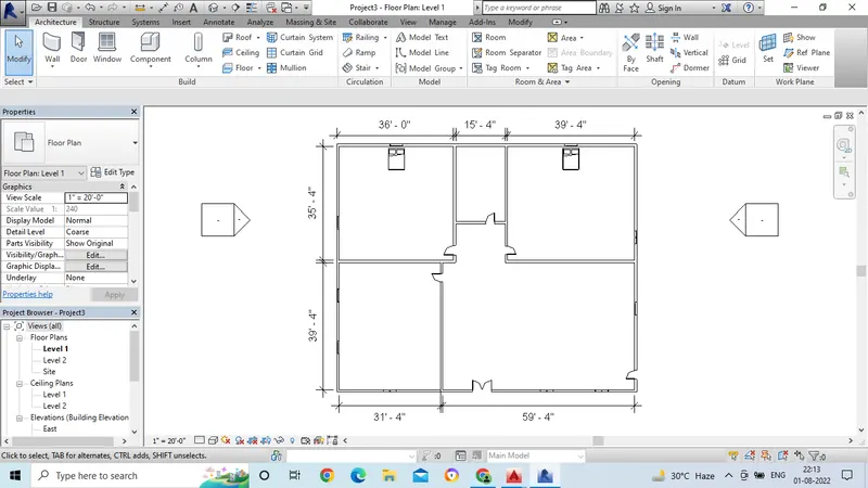
- After completing the residential drawing, we have to mention dimensions to the rooms.
- For this we have 3 options to mention the dimensions.
- By choosing the option from the Annotate tab, we can give the dimensions.
- By taking the points from one edge to the other edge we can give the dimensions.
- Now we have to create a ceiling for the first floor plan.
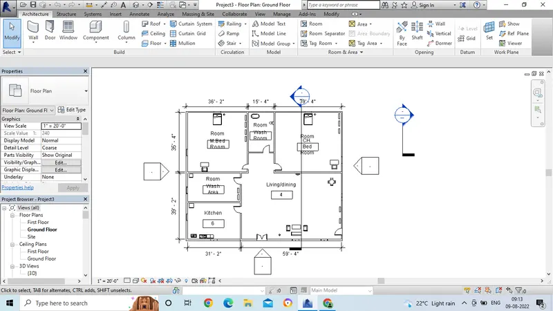
- For preparing ceiling for the first floor, go to ceiling command from the Architecture tab.
- Then go to sketch ceiling option.
-
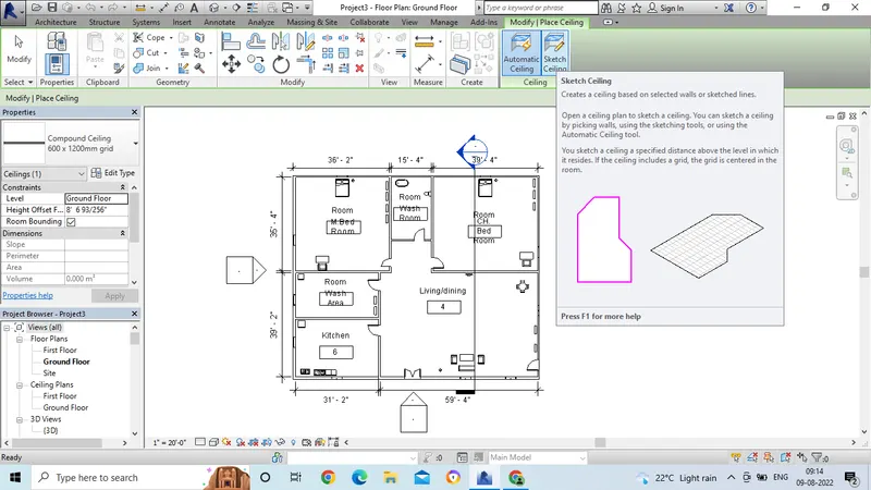
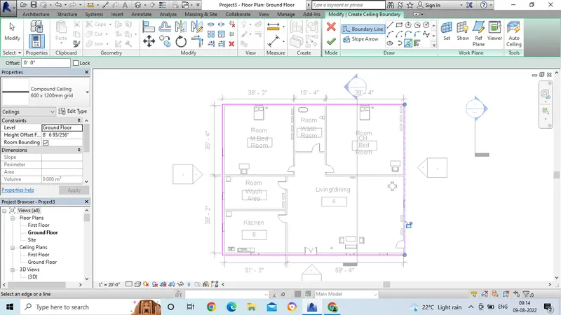
- Then the drawing command box will get open.
- From that select line or pick line option.
- Then draw the lines for the outer wall or select the outer line pick wall option.
- Then ceiling will be applied to the first floor level.
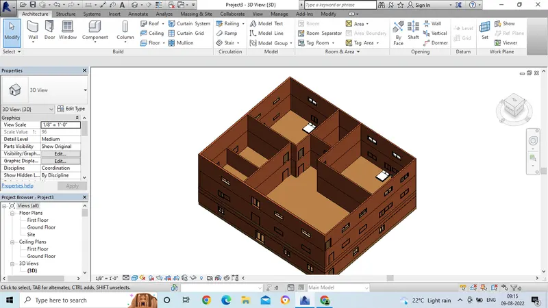
- To check the ceiling, go to 3d view option.
- Then we can see the ceiling option for the building.
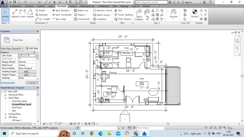
- Now go to the ground floor plan and select the floor plan from the plan view option.
- Then go to the annotate tool bar and select the linear or aligned option for dimensioning.
- Then select the points properly end to end and we can get the dimension.
- In the same way give the dimensions for all the outer and inner walls.
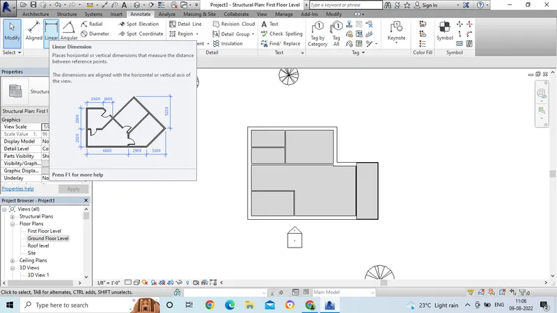
- Now take the structural floor plan from the plan view.
- In the same way, give the dimensions by selecting linear or aligned option.
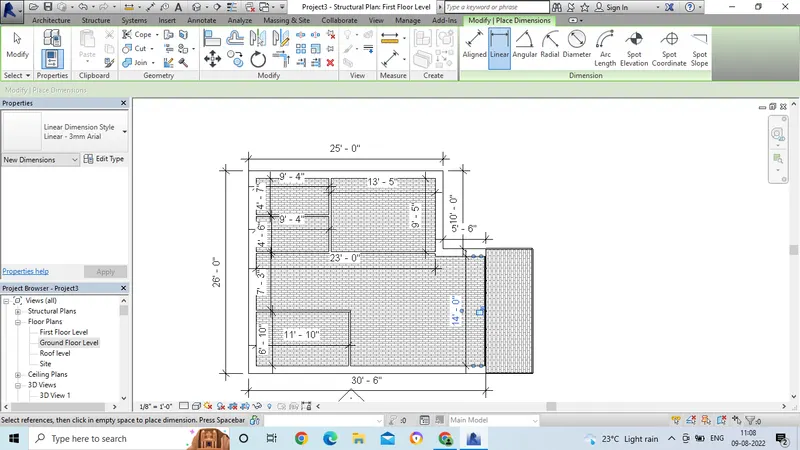
- Now go to the structural ground floor plan and select the floor plan from the plan view option.
- Then go to the annotate tool bar and select the linear or aligned option for dimensioning.
- Then select the points properly end to end and we can get the dimension.
- In the same way give the dimensions for all the outer and inner walls.
- In this model, we have to create the roof plan for the building.
- Go to Architecture tab and select roof command.
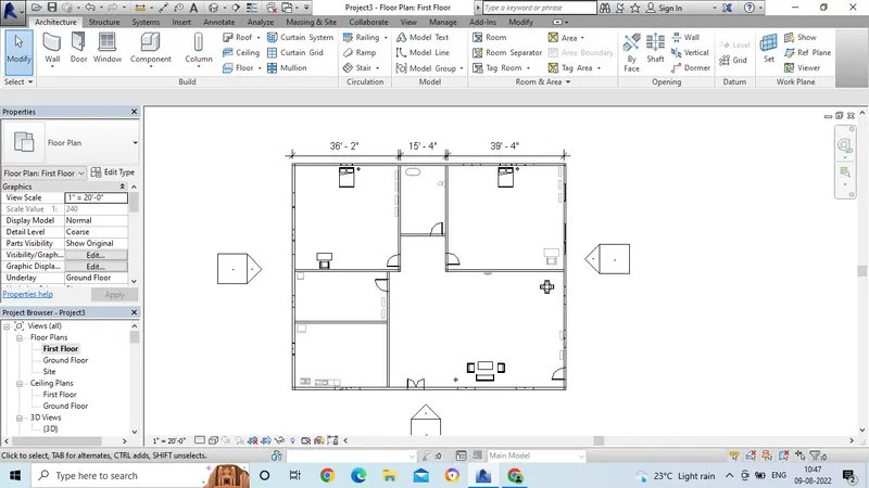
- From the roof command, then the draw command option will get open.
- From that, take line or pick line option.
- Then go to first floor plan in the properties browser option.
- Now take line or pick line option, then select the outer wall boundary option.
-
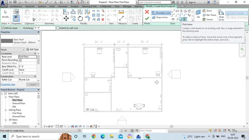
- Then the roof plan will get applied on the top of the floor.
- Now the top roof surface should be in 10degrees.
-
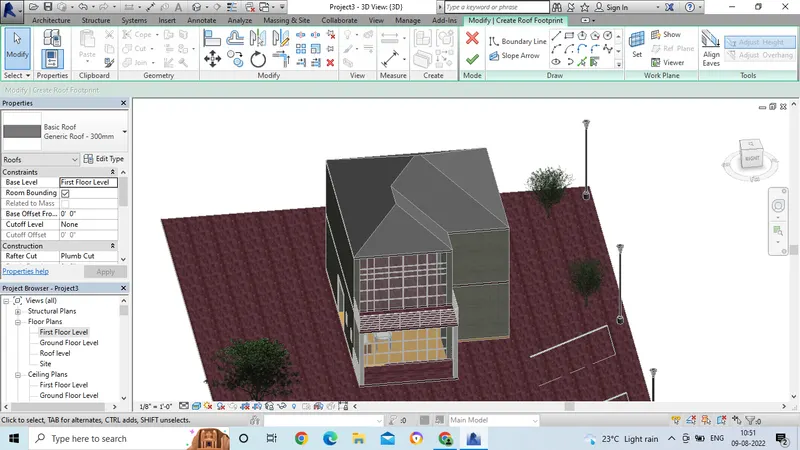
- Go to properties option, then select the scope option.
- Take 10deg for the roof top surface by selecting roof surface area.
- Then click on apply option.
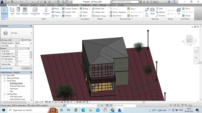
- Now the roof top surface is changed to 10deg.
2. Aim: To create the reasonable assumptions for geographic and location details for the project modelling based on the assumptions and type of the structure selected and to identify the modelling requirements form NBC.
Introduction: To create the reasonable assumptions for geographic and location details for the project modelling based on the assumptions and type of the structure selected and to identify the modelling requirements form NBC.
Procedure:
- Here i have choosen to design residential building as per the NBC 2006.
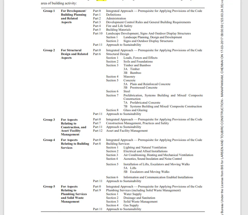
- For that depends upon the type of the structure we have to choose the rules followed by the NBC.
-
Groups of National Building codes:-
Based on NBC, we can sub divided the group as 9.
- Group-A:- Residential Building.
- Group-B:- Educational Building.
- Group-C:- Assembly Building.
- Group-D:- Institutional Building.
- Group-E:- Mercantile Building.
- Group-F:- Business building.
- Group-G:- Storage Buidling.
- Group-H:- Industrial Buidling.
- Group-I:- Hazardous Building.
Building codes for modeling/efficiency of drawing in revit:-
- The National Building code is a document that provides guidelines for construction of structures like Residential, Institutional, Educational, Commercial, Assembly, and storage spaces.
- It is important to follow these guidelines that are meant to protect the overall wealth of the construction and ensure the health and safety of the public and the residence.
- These standards are published in 1970 and revised in later in 1983.
- The latest version of National Building code is 2016.
- A set of standards that are uniform to all structures.
- These building codes are provide a set of standards that are uniform to all the structures.
- So that they gain the modeling process.
- These codes protects the overall wealth of the construction and public residence.
- Then the designer constantly refer these building codes for modeling which enhance their knowledge in this field.
- It also enables the modern construction menthods with the standard conventional standards.
- Tese standards also help the government to approve the plans as it become the lack of particular juridiction by the appropriate govenrment or authority.
- Therefore it provides the building standards with the approval of government agencies for approving of the plan.
Height Limitations:-
- As per NBC 2005, Clause C-2.5, the height of the building shall not exceed 15m.
- Then there is no need to provide lifts.
- Housing for low income groups shall preferably be up to maximum fo two storeys.
- Buildings for housing beyond 15m in height shall be restored to in exceptional circumstances and should be governed by the provisions laid down in the code.
- About my model - The height of the building in my model is 6.4m which is less than 15m. Hence it follows NBC guidelines.
- Area limitations:- According to NBC 2005, the minimum pot size with ground coverage not exceeding 75%, shall not be less than 40 sq.m in small and medium town and not less tha 30 sq.m in metropolitan areas.
- Plot sizes below 30m^2 but not less than 15m may be permitted in case of cluster planning.
- However in such cases the ground coverage and FSI shall be 100 percent and 2 percent respectively.
- About my model:- The area occupied by the bulding in my model is greater than 60 sq.m. Floor area of my model is 47'8"X 40'8" i.e., 175 sq.m
- Room Sizing:- Every dwelling unit to be provided should have at least two habitable rooms.
- Even if one room house is provided initially it should be capable of adding a new second room in future.
- However, In case single room tenements are required to be provided where future additions are not possible,
- the carpet area of multipurpose single room should be atleast 12.5m^2.
- Such one room dwelling units with 12.5m^2 carpet area of habitable space is permitted only incase of on site reahbilitation of slum dwellers.
- In a hous of 2 rooms, first room shall not be less that 9.0m and minimum width of 2.5 m provided and second room shall not be less than 6.5 m^2 with a minimum width of 2.1m.
- In incremental housing the bigger room shall always be the first room.
- Wall Height: Accoding to the NBC 2005 clause F-3.4, the minimum height of rooms and spaces shall be
- A. habitable room - 2.75m
- B.Kitchen - 2.6m
- C. bath/Water closet - 2.2m
- Corridors - 2.1m
- In case of sloping roof of the coverage height of roofs for habitable rooms hsall be 2.75m and minimum height shall be 2.1m.
- In my model the wall has the height of 3m and satisfirs the NBC.
- Thickness based on fire and life safety:- The thickness for masonary walls is given by the table 2 of fire and life safety section of NBC 2005
- In my model the wall thickness is 8" which is greater that NBC model.
- Passageway Requirements: As per NBC 2005, Table 1
- In my model it satisfies all the requirements.
Modeling requirements for the project are:-
A. Height Limitations:-
- As per NBC 2005, Clause C-2.5, the height of the building shall not exceed 15m.
- Then there is no need to provide lifts.
- Housing for low income groups shall preferably be up to maximum fo two storeys.
- Buildings for housing beyond 15m in height shall be restored to in exceptional circumstances and should be governed by the provisions laid down in the code.
- About my model - The height of the building in my model is 6.4m which is less than 15m. Hence it follows NBC guidelines.
- Area limitations:- According to NBC 2005, the minimum pot size with ground coverage not exceeding 75%, shall not be less than 40 sq.m in small and medium town and not less tha 30 sq.m in metropolitan areas.
- Plot sizes below 30m^2 but not less than 15m may be permitted in case of cluster planning.
- However in such cases the ground coverage and FSI shall be 100 percent and 2 percent respectively.
- About my model:- The area occupied by the bulding in my model is greater than 60 sq.m. Floor area of my model is 47'8"X 40'8" i.e., 175 sq.m
- Room Sizing:- Every dwelling unit to be provided should have at least two habitable rooms.
- Even if one room house is provided initially it should be capable of adding a new second room in future.
- However, In case single room tenements are required to be provided where future additions are not possible,
- the carpet area of multipurpose single room should be atleast 12.5m^2.
- Such one room dwelling units with 12.5m^2 carpet area of habitable space is permitted only incase of on site reahbilitation of slum dwellers.
- In a hous of 2 rooms, first room shall not be less that 9.0m and minimum width of 2.5 m provided and second room shall not be less than 6.5 m^2 with a minimum width of 2.1m.
- In incremental housing the bigger room shall always be the first room.
- Wall Height: Accoding to the NBC 2005 clause F-3.4, the minimum height of rooms and spaces shall be
- A. habitable room - 2.75m
- B.Kitchen - 2.6m
- C. bath/Water closet - 2.2m
- Corridors - 2.1m
- In case of sloping roof of the coverage height of roofs for habitable rooms hsall be 2.75m and minimum height shall be 2.1m.
- In my model the wall has the height of 3m and satisfirs the NBC.
- Thickness based on fire and life safety:- The thickness for masonary walls is given by the table 2 of fire and life safety section of NBC 2005
- In my model the wall thickness is 8" which is greater that NBC model.
- Passageway Requirements: As per NBC 2005, Table 1
- In my model it satisfies all the requirements.
3. Aim: To create the models in the structural component which is given in the attachment on the type of structure selected.
Introduction: To create the models in the structural component which is given in the attachment on the type of structure selected.
Procedure:
- Open the revit software and open the structural template.
- Then go to project browser and select the level.
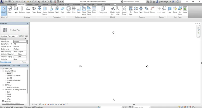
- Then go to modify tab in the menu bar.
- Draw the horizantal and transverse grid lines in the sheet.
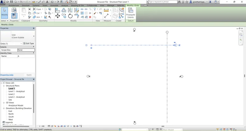
- Now select pic line option in the modify bar.
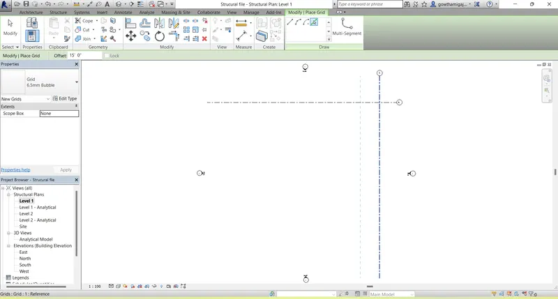
- After selecting the pick line option, select the grid line and do offset the gird lines in the longitudinal direction.
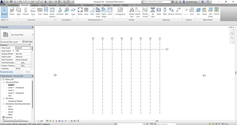
- In the same way by selecting the picline option in the modify bar,
- Now draw the grid lines in the transverse direction.
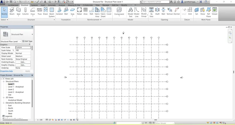
- Go to the structure tab and select the foundation command.
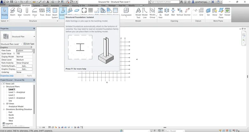
- Then select the foundation size in the properties.
- Now click on the at grids option.
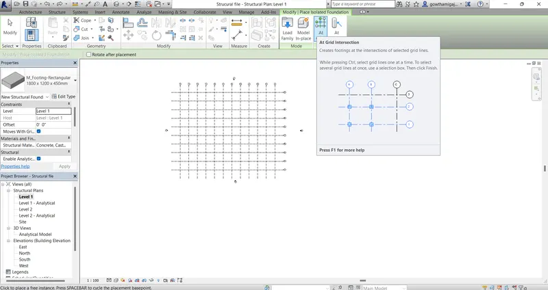
- Now select all the grids from one corner to another corner of the grids.
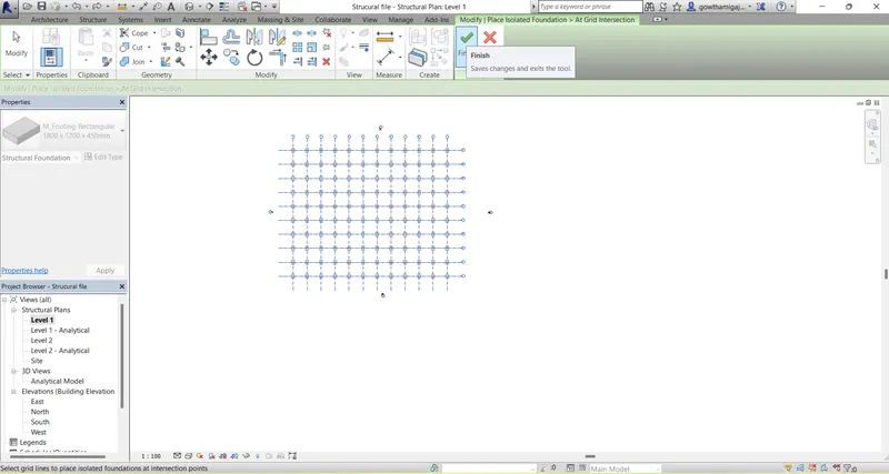
- Then we can see the foundation is assigned to all the grids.
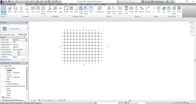
- Now go to the 3d view to see the foundation levels in the grids.
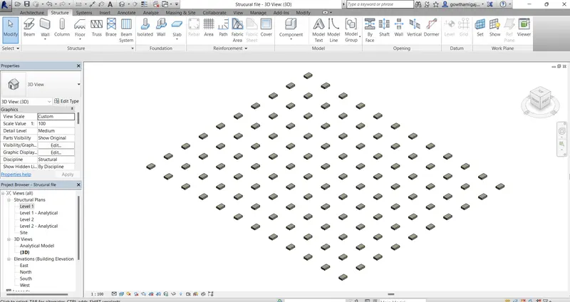
- After the foundation, we have to assign columns to the foundation in the grids.
- For that, go to the structure tab and select column.
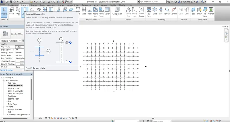
- Now select the vertical column in the modify tool bar.
- Then select the column size from the properties.
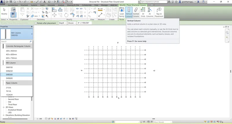
- Now click on at grids.
- Select the grids from one corner to other orner of the grids.
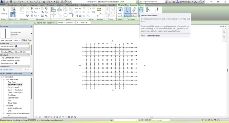
- Select all the grids for placing the columns.
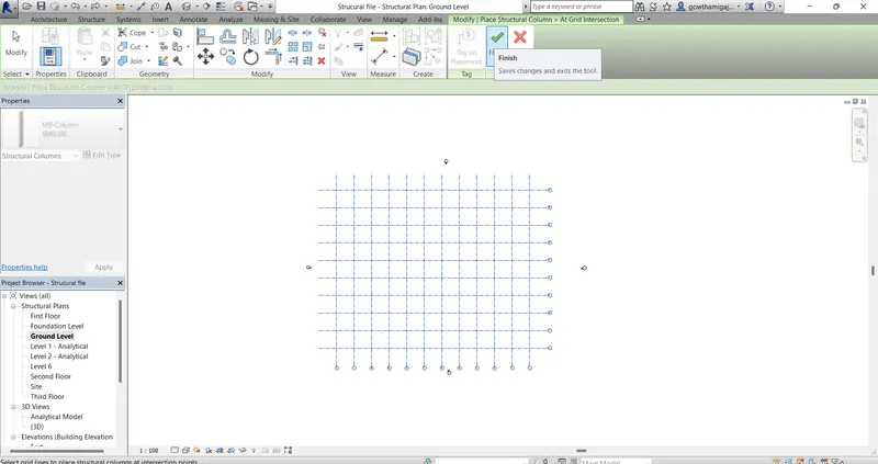
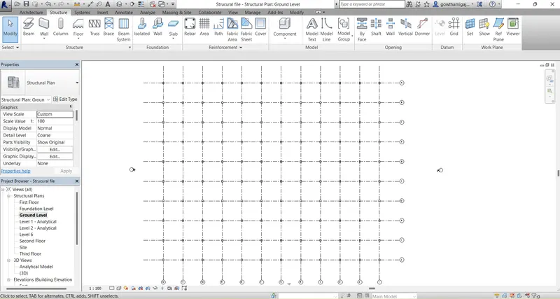
- Now we can see the columns placed in the grids.
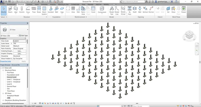
- Then go to the 3d view and we can see the columns placing at the foundation levels.
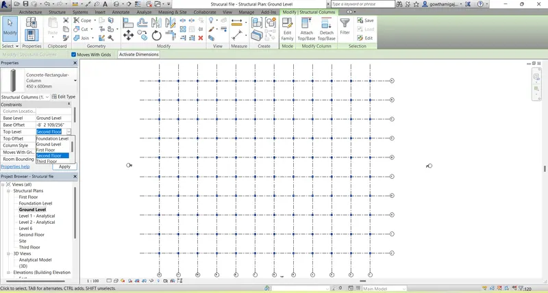
- Now after placing the columns in the ground floor, copy them to the first and second floor levels.
- Go to the properties bar and click on Top level as second floor.
- Now we can see the columns upto the second floor level.
- Now we have to place the beams.
- For that go to the structure bar and select beams.
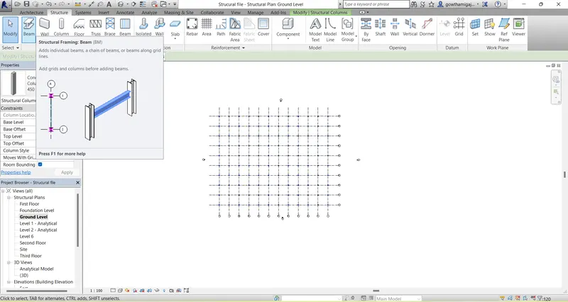
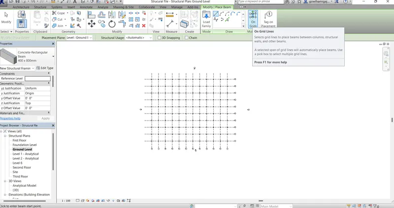
- Then select the on grids option in the modify bar.
- And also select the beam size which is to be placed in the grids.
- Now the beams are placed on the grids.
- Then click on the ground floor level.
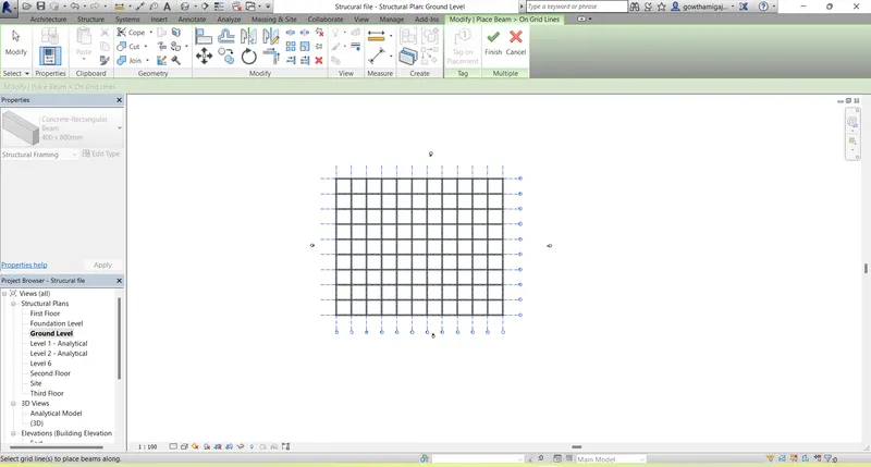
- Then select the tick mark in the modify bar.
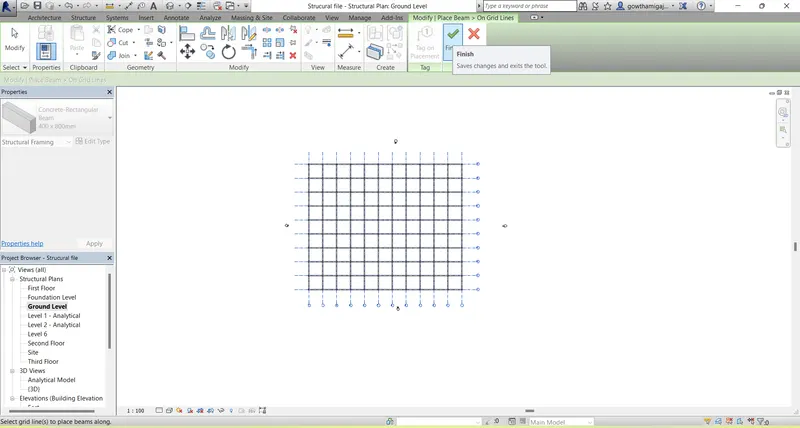
- Now beams are placed on the grids.
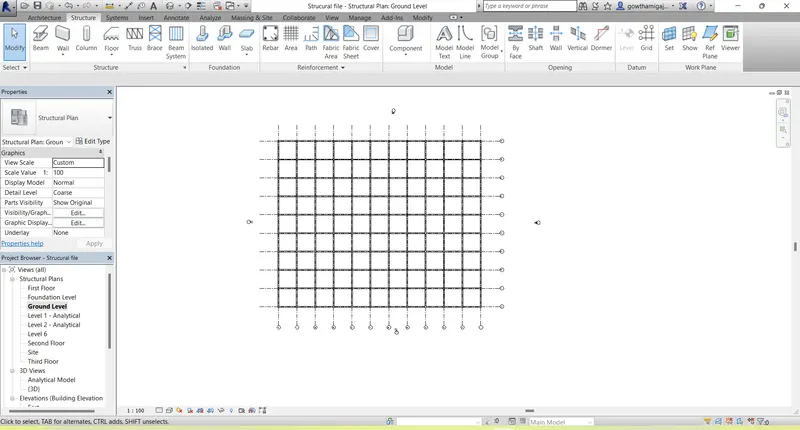
- Then coonvert to the 3D view and there we can see the beams placed in the ground floor.
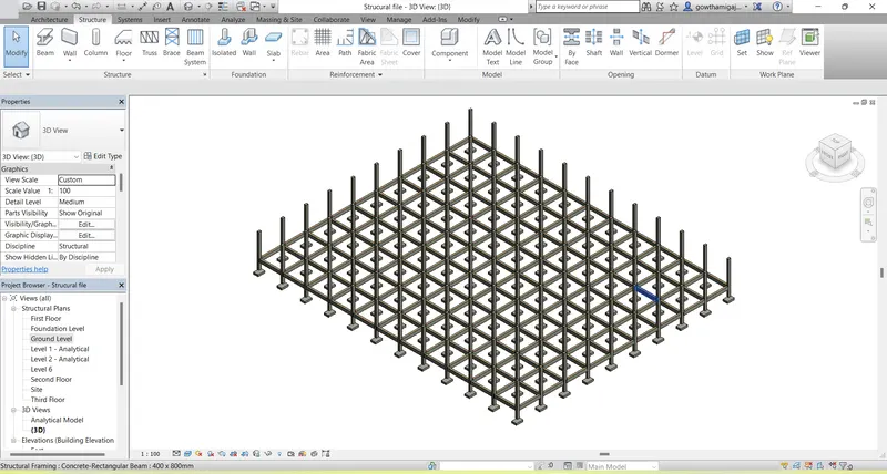
- Now go to the structure tab.
- Select the ground floor level in the project browser.
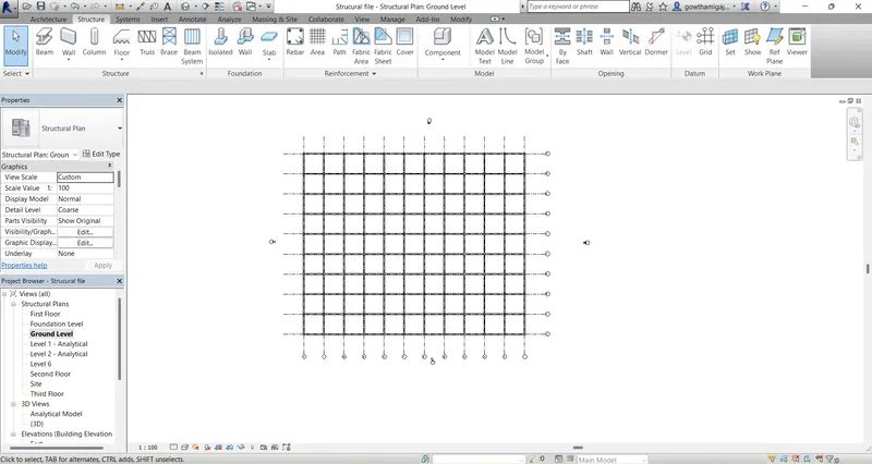
- Then select on grids option.
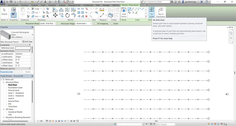
- Now select all the grids in the first floor.
- Then click on finish in the modify tool bar.
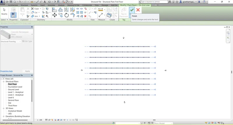
- Now we have to add the floor to the beams.
- For that go to the structure tab and select floor command.
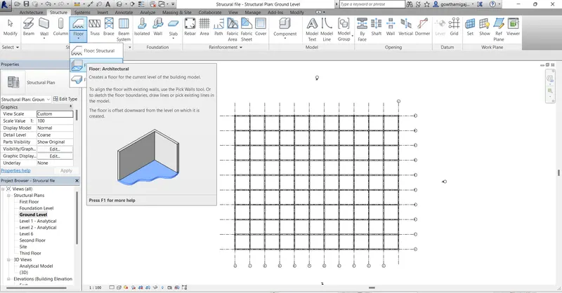
- Now click on the boundary leven in the modify tool bar.
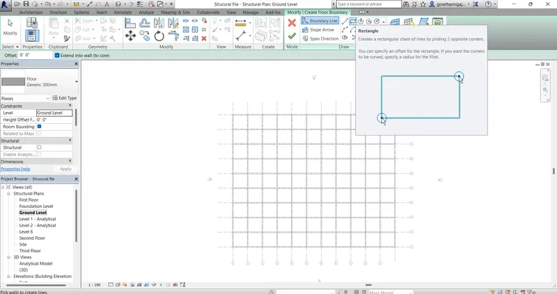
- Now after creating the boundary line, click on finish.
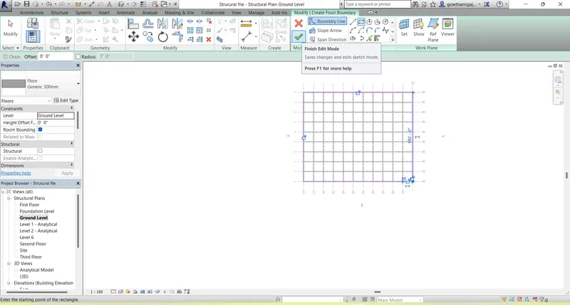
- Then we can see the floor boundary on the grid lines.
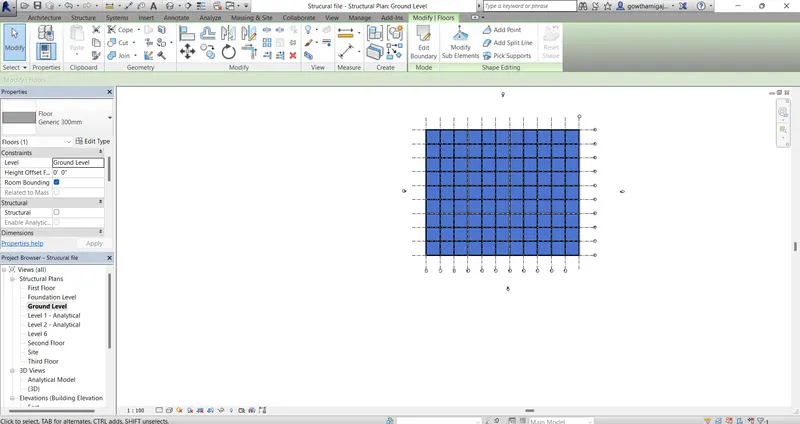
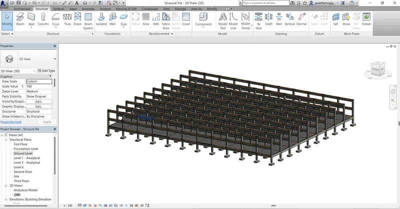
- Go to the 3d view and floor is created in the ground floor level.
- Now we have to place shaft opening.
- For that click on the ground floor level in the project browser.
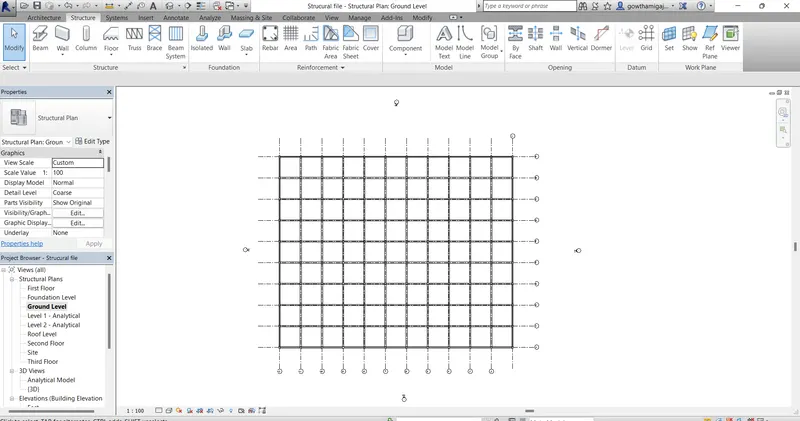
- Go to the Architecture tab and select the shaft tool bar.
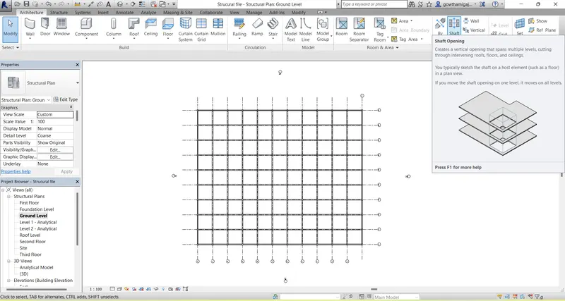
- Now draw the shaft line by using line or rectangle command on the ground floor level.
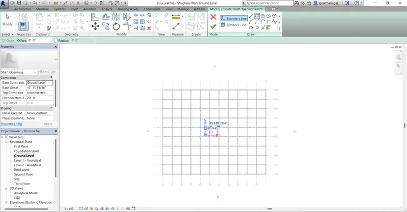
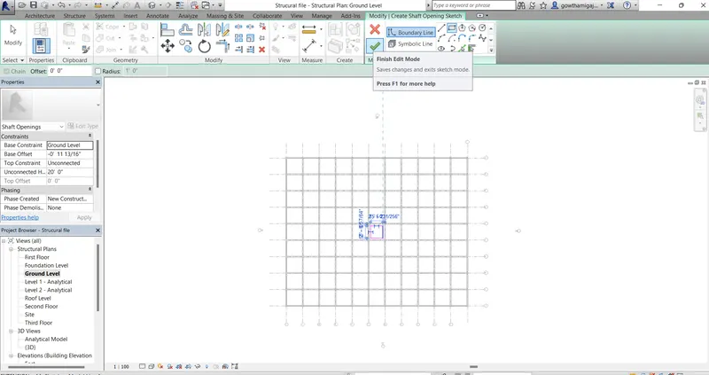
- Then after creating the shaft lines click on finish.
- Now we can see the shaft placed on the ground floor level.
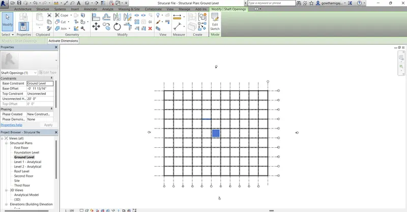
- Go to the 3d view and there we can see the shaft opening for staircase or lift.
- If the shaft opening is not displayed then we can adjust the levels in the properties bar.
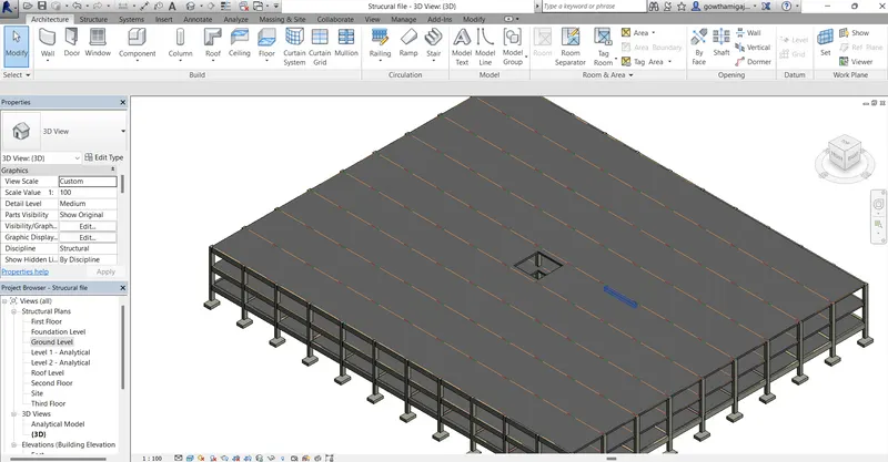
Result:
4. Aim: To create the architectural model including the furniture components based on the type of structure used.
Introduction: To create the architectural model including the furniture components based on the type of structure used.
Procedure:
- Go to revit and open the drawing.
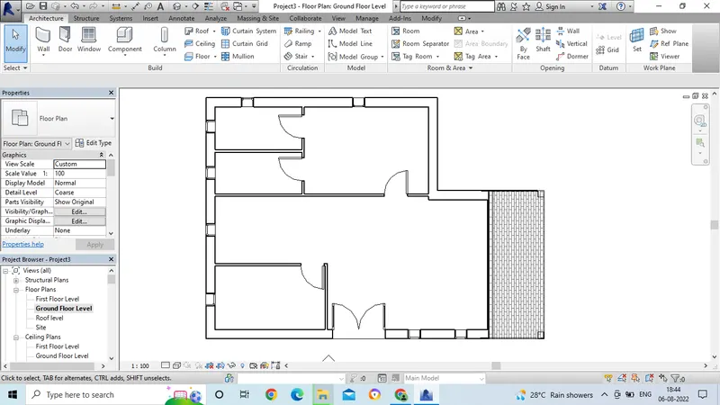
- We have to divide the room areas for the residential unit.
- For that go for the Architecture tab and select the wall command.
- Then draw the wall from the given dimenisons.
- And also as per vaastu we have to divide the room areas.
- Then separate the room portions as per the requirement.
- After placing the rooms we have to mention the text for the rooms.
- For that go to the Architecture tab.
- Select the room area.
- Then click on all the rooms.
- Then edit the text and give proper names to the room areas.
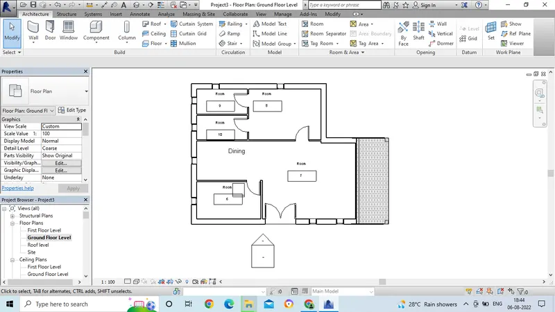
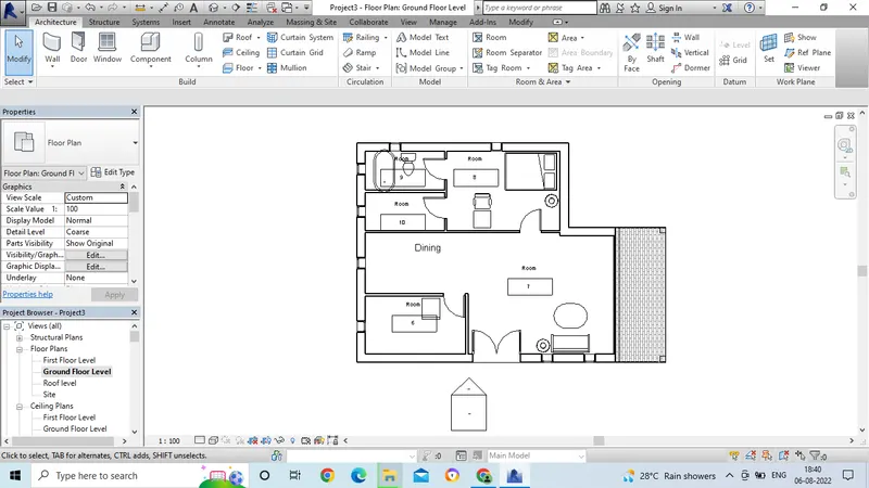
- After givinng the room names, edit the room names by clicking double click.
- Then we have to apply the furniture to the room areas.
- Next for giving the material to the wall we have to select edit command in the project browser.
- Select the material which is to be edit the material.
- After selecting the edit command next we have to click on by category.
- In this by category option we can change the material.
- And also the colour for material also can be changed.
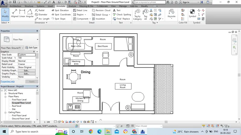
- We have to add the material to the residential unit by loading the material from the families.
- First we have to select the component command and in that select the place a component.
- Then click on the load families option.
- Then families tab will get open.
- For the living room as in the given attachment we have to give the proper furniture.
- Once we select the furniture then click open.
- Then we have to place the furniture wherever it is necessary.
- We can select and move the furniture after placing.
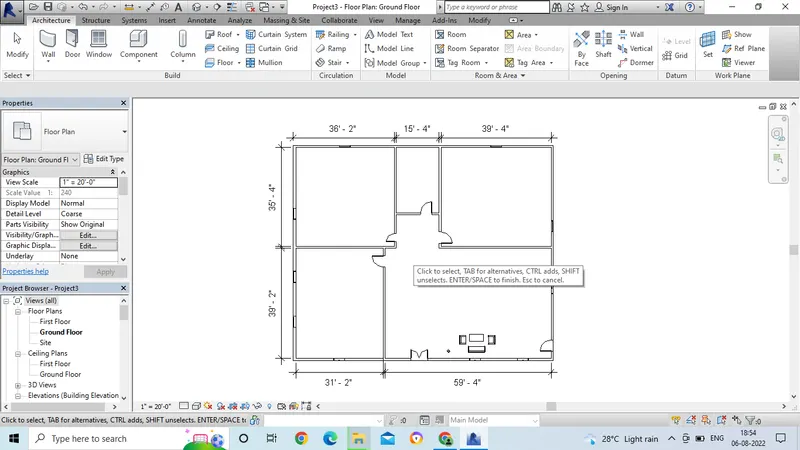
- In the same way, go for the bed room and place the furniture.
- Select the bed size and place the bed as per the dimension.
- Then we have to place for te table and chair for study purpose.
- And also we can edit the material as per por requirement.
- Go for the edit option in the project browser.
- Then choose for the material and size of the bed.
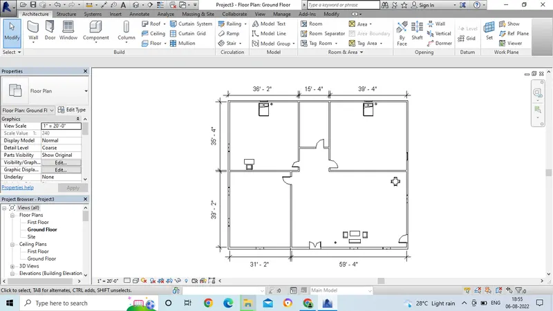
- In the same way, go for the another bed room and place the furniture.
- Select the bed size and place the bed as per the dimension.
- Then we have to place for te table and chair for study purpose.
- And place the dining wherever it is required.
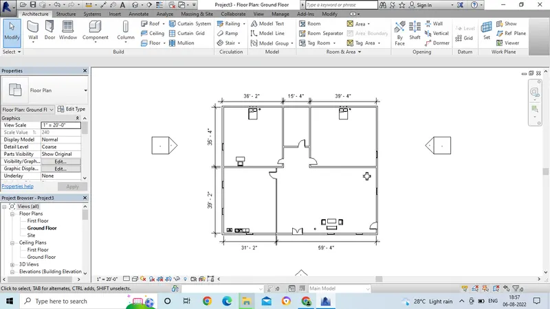
- In the same way, give the material to all the room for kitchen, wash area and wash room.
- After placing the material we have to mention the text for the rooms.
- For that go to the Architecture tab.
- Select the room area.
- Then click on all the rooms.
- Then edit the text and give proper names to the room areas.
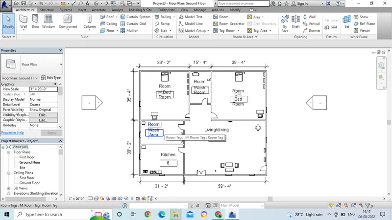
- First we have to open the revit software by selecting proper template which is to be used.
- Next for giving the material to the wall we have to select edit command in the project browser.
- Select the material which is to be edit the material.
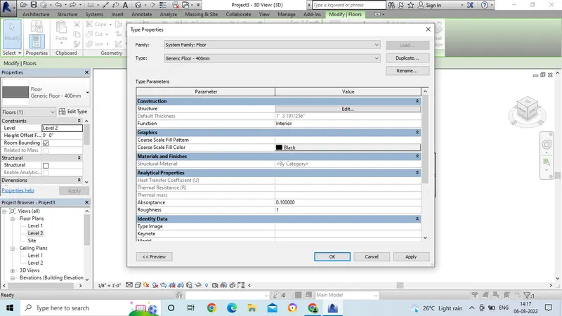
- After selecting the edit command next we have to click on by category.
- In this by category option we can change the material.
- And also the colour for material can be changed.
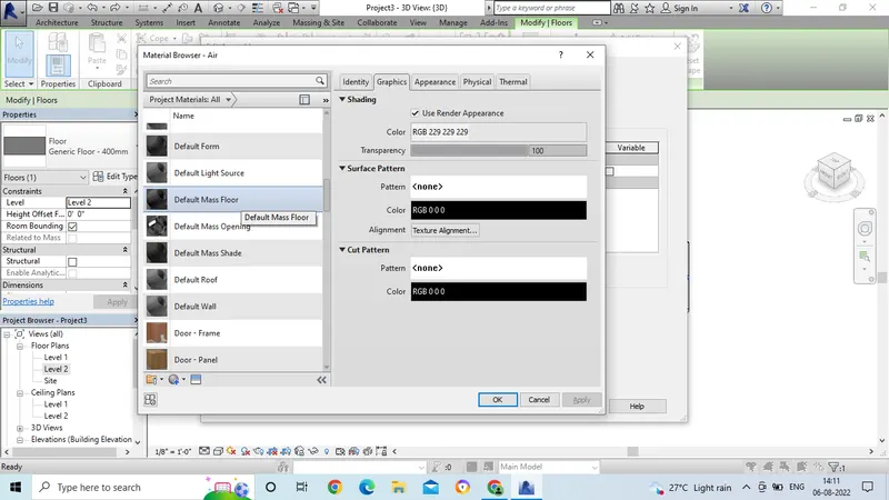
- After selecting the material then select for thickness.
- Then click "Ok".
- And then Apply and then "Ok".
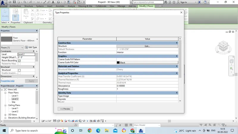
- After applying the material, go to the 3D view.
- Then select for shaded or realistic view.
- Then the final drawing will appear after applying the material.
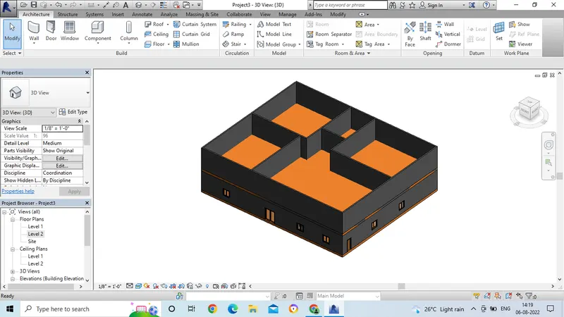
- In the same way by editing the material, we have to edit the thickness of the wall.
- In the Property browser click on the edit option.
- Then we can change the thickness of the wall.
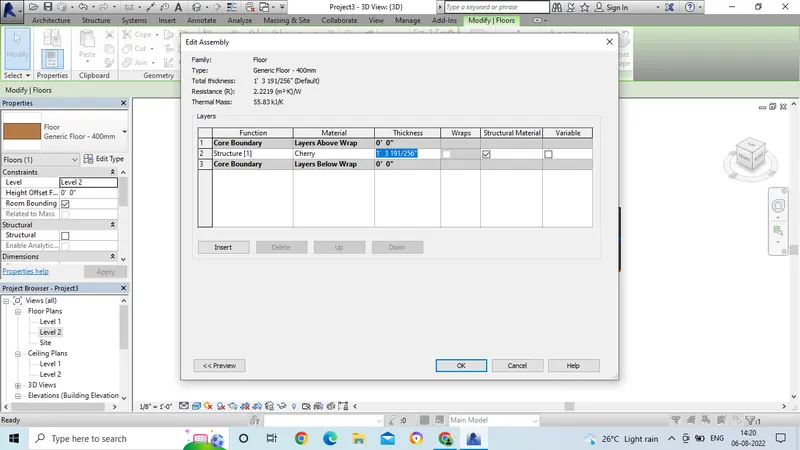
- After applying the thickness, go to the 3D view.
- Then select for shaded or realisitic view.
- Then the final drawing will appear after applying the material.
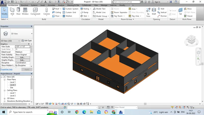
- In the Architecture tab, by using the wall command we have to draw the walls.
- Then separate the rooms by using wall command.
- Then go for 3D view.
- Next for giving the material to the wall we have to select edit command in the project browser.
- Select the material which is to be edit the material.
- After selecting the edit command next we have to click on by category.
- In this by category option we can change the material.
- And also the colour for material also can be changed.
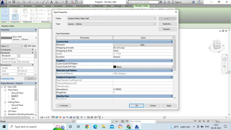
- After selecting the material then select for thickness.
- Then click "Ok".
- And then Apply and then "Ok".
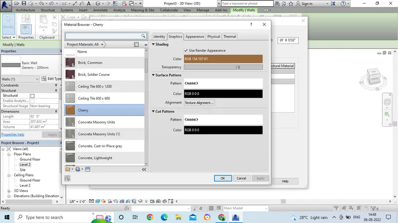
- After applying the thickness, go to the 3D view.
- Then select for shaded or realsitic view.
- Then the final drawing will appear after applying the material.
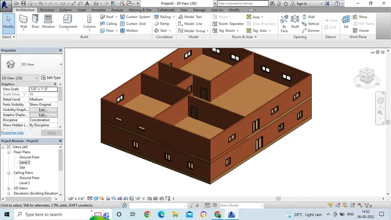
- In the same way by editing the material, we have to edit the thickness of the wall.
- In the Property browser click on the edit option.
- Then we can change the thickness of the wall.
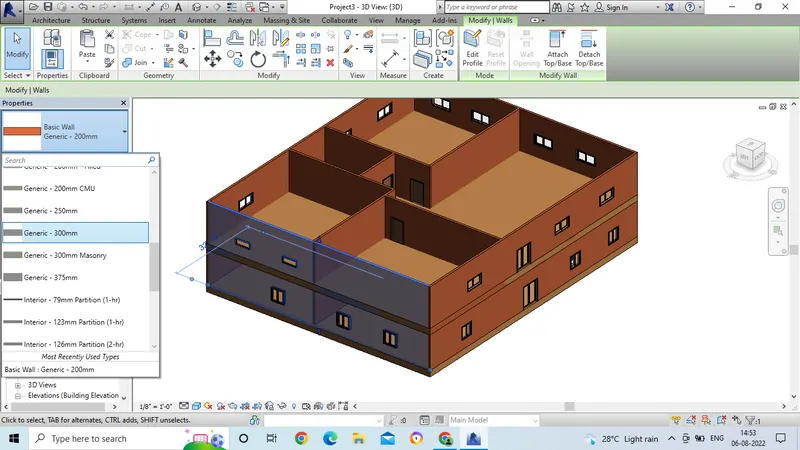
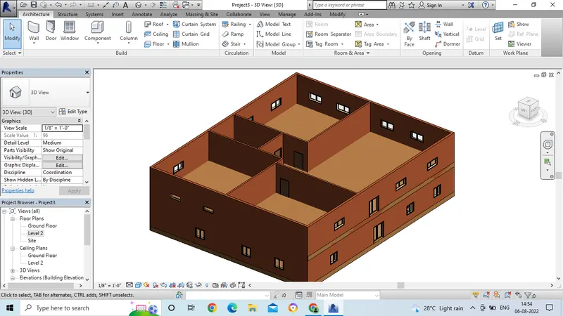
- After creating the ground floor, we have to go for first floor.
- We can copy the elements which are created in the ground floor.
- We have to select the ground floor.
- Then we will get a command tool bar after selecting the material.
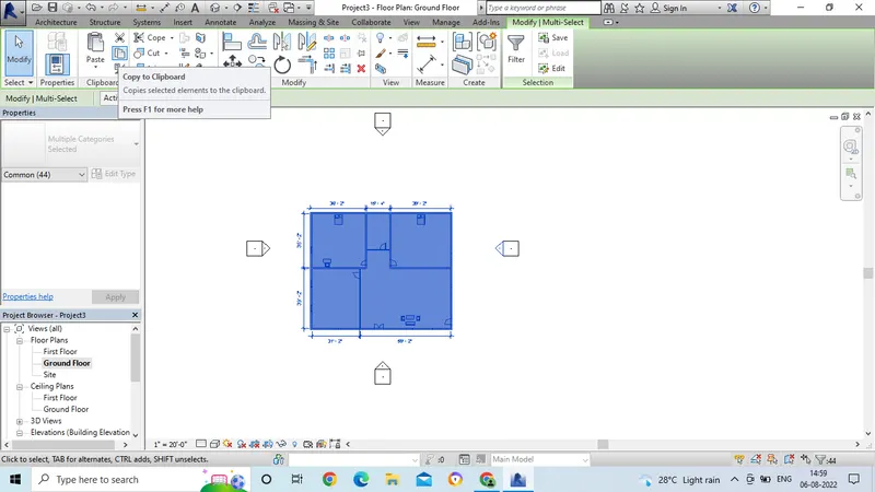
- Then select for the copy to clipboard option.
- Then select the paste option.
- In the paste option select for the Aligned to the clipboard.
- Then the first floor is copied with material.
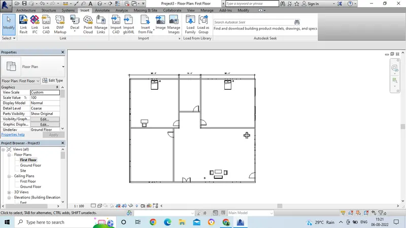
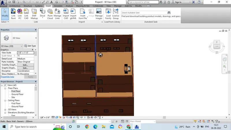
- After creating the first floor go for 3D view.
- In the view command select 3D view.
- Then final drawing is ready.
Result:
5. Aim: To create a set of drawings in an architectural and structural model with categories and appropriate sheet templates.
Introduction: To create a set of drawings in an architectural and structural model with categories and appropriate sheet templates.
Procedure:
A. Floor Plan:
- In this we hae to create a floor plan for each floor.
- Go to revit software and open the file from the previous drawings.
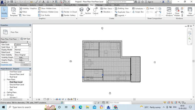
- Go to view command and select floor plan.
- In the Floor plan, select all the layers from the dialogue box.
- Then cick ok.
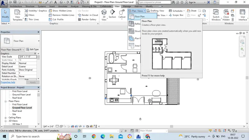
- Now go to the project browser, and select first floor.
- Then we can see the floor plan for the first plan.
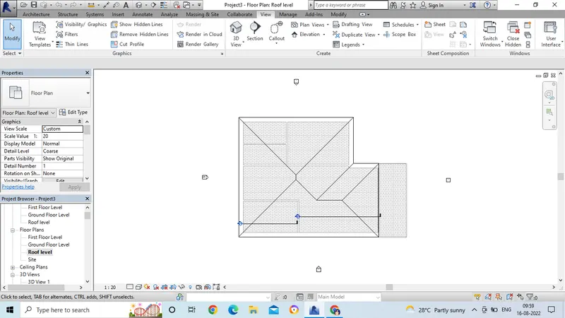
- In the same way, select for the roof floor level.
A. Elevation:
- First we need to open the revit software and open the drawing.
- Then go to the view option.
- Now go to the elevation option and click on elevation.
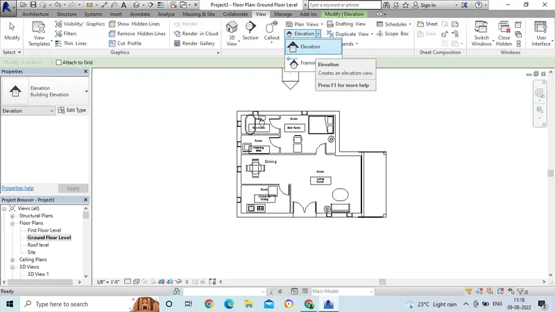
- Now we will see the point option.
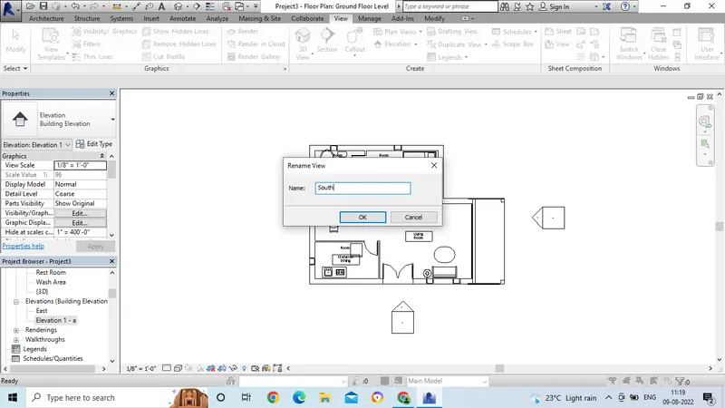
- Click the point option on one side.
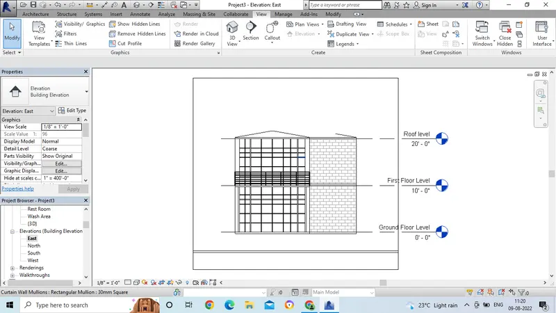
- Now in the project browser, we will see the elvation option.
- Then rename the elevation view as South.
- In the same way, again click the point to the other side.
- And rename the view as East.
- Then after changing the name, double click on the elavation name option.
- then the elavation view will get opened.
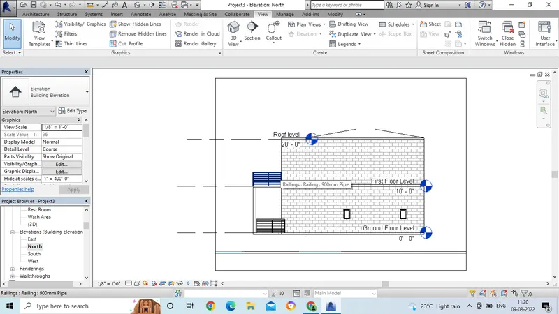
- Now for the North side elevation view option.
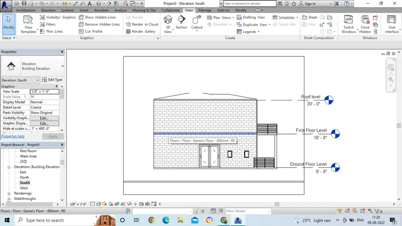
- Now for the south side elevation view option.
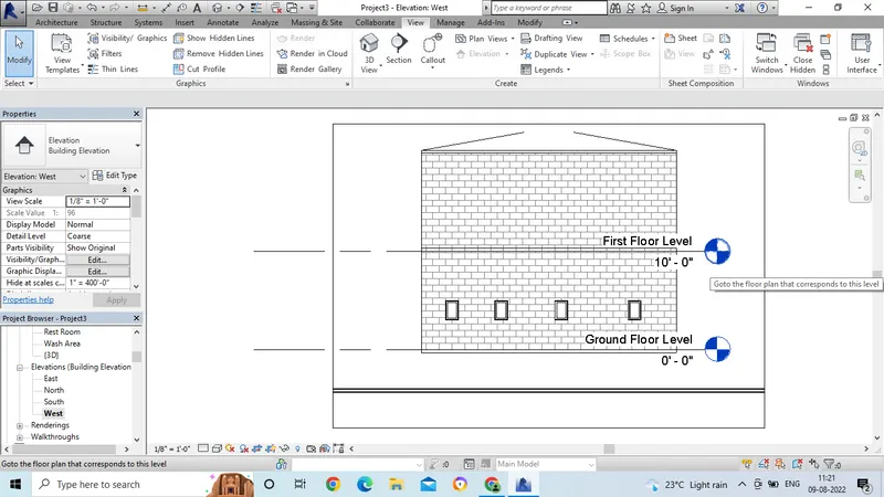
- Now for the West side elevation view option.
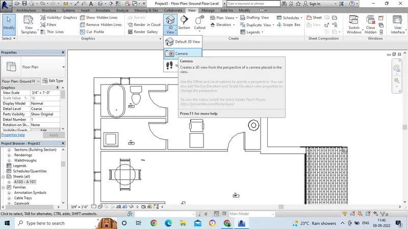
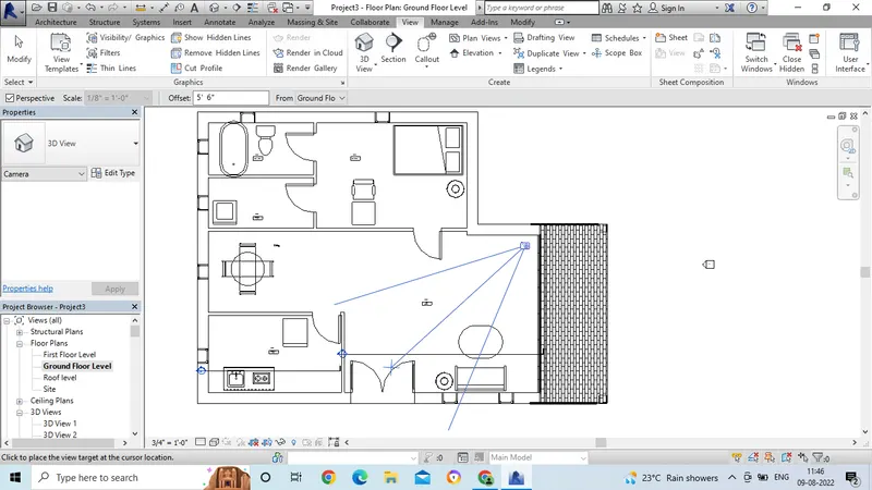
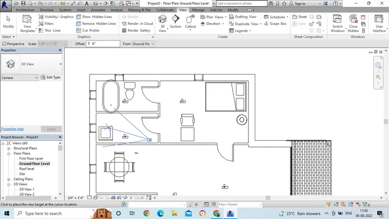
- Then for creating the camera view go the view option.
- In that select 3d view, and select the camera option.
- Now place the camera in which we want to view.
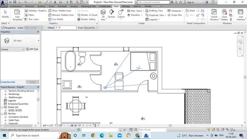
-
- Then after placing the camera we can see the camera lense liness which are passing in the room.
- Now select the view from the project browser.
- And adjust the lines of the camera view.
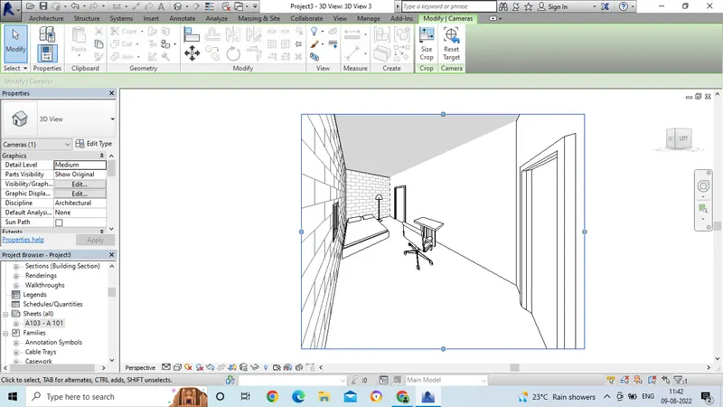
- For clear view select the realistic option.
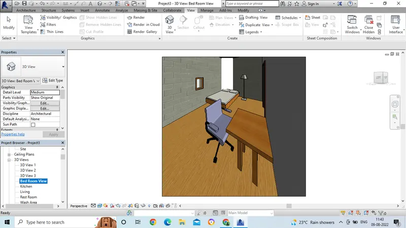
- Now the fnal 3D view is ready for bed room.
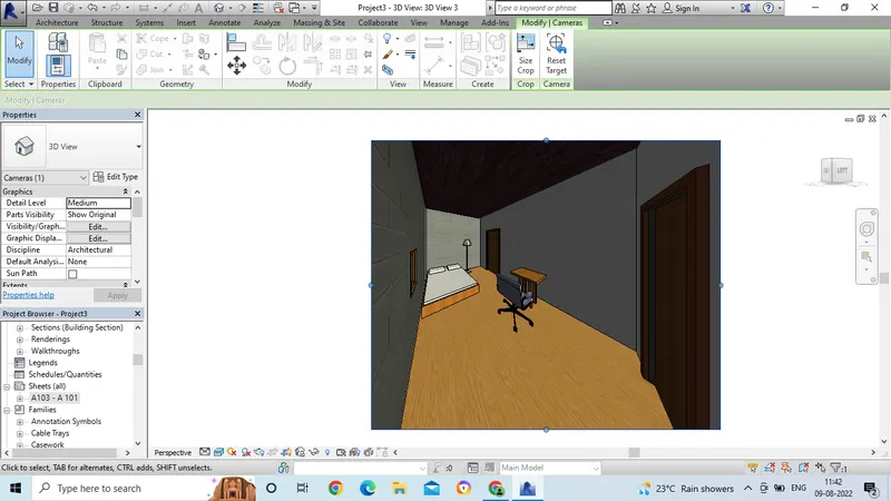
- Select the view and change the name in the project browser as Bed room view.
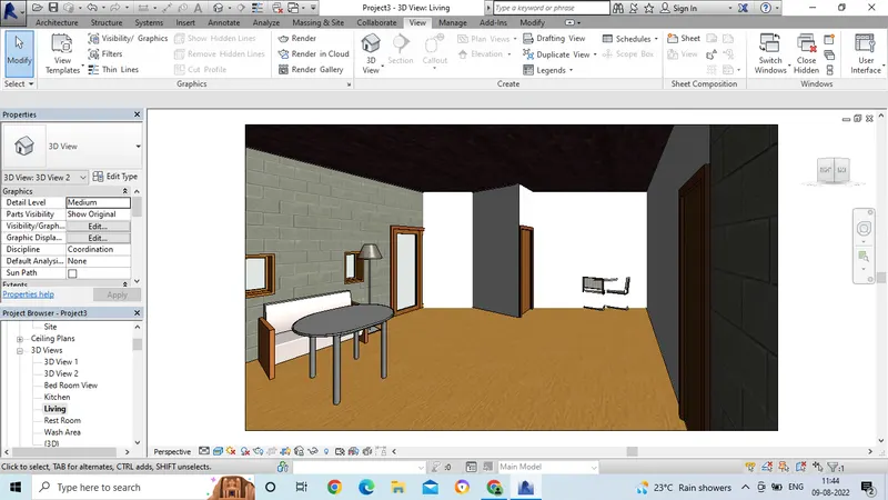
- In the same way, now the camera view is applied to living room.
- We can see the living room area in 3d view.
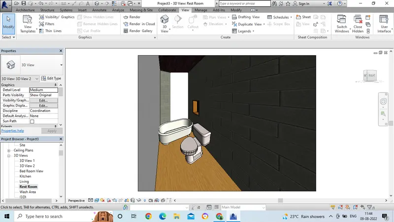
- In the same way, Now the camera view is applied to Rest room.
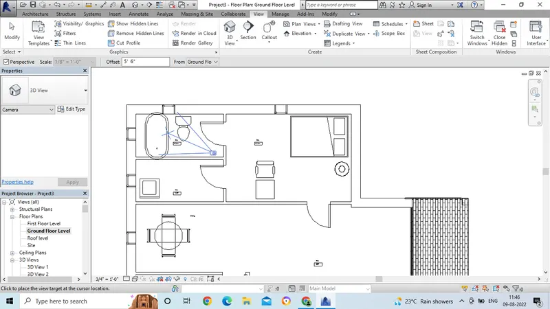
- We can see the 3D view of the Rest room area.
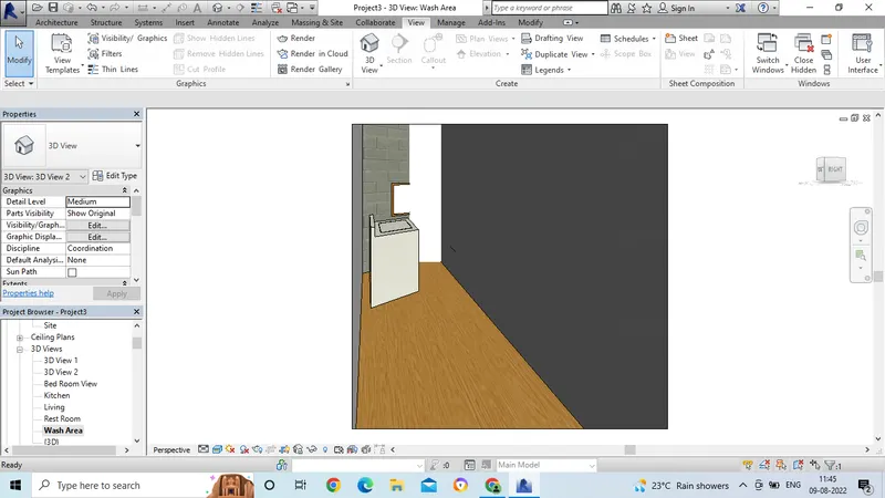
- In the same way, now the camera view is applied to wash area.
- Now we can see the 3D view of wash area.
- After creating the views, we have to place the view in the sheets.
- Select the sheet in the view option.
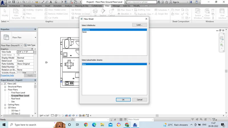
- Now the sheet will get open.
- Now we have to place the 3d view which we have created, we have to place in the sheet.
- Select the view from the project browser and drag in to the sheet.
- Adjust the view range and ajust the scale and insert the drawin in the sheet.
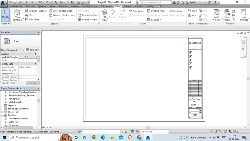
- Now drag the elevation view image to the sheet.
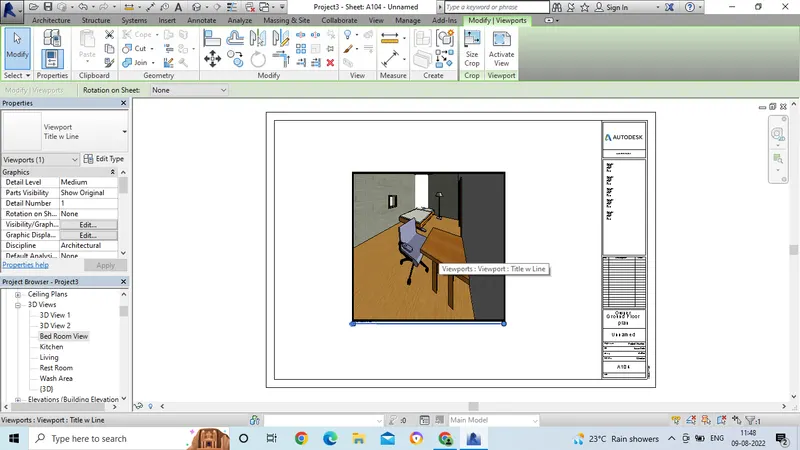
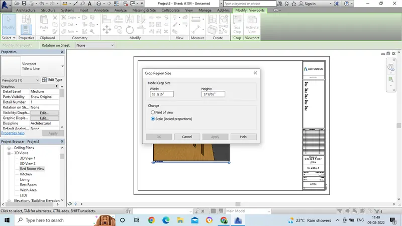
- Now to adjust the image, select the size crop option in the modify tool bar.
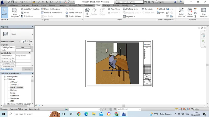
- And adjust the scale to the drawing.
- Now we can see the image after adjusting the image withe proper scale.
- First we need to open the revit software and open the drawing by using the proper template.
- Then go to the view option.
- Next click on the section
- Then the section line will appear on the screen.
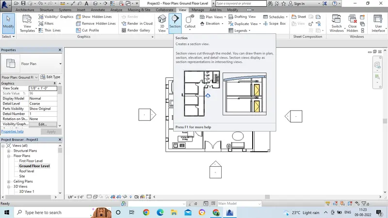
Section:
- Select the area in which area we need to show the section .
- In this view, we have taken the horizantal view section.
- And section is drawn in the horizantal view.
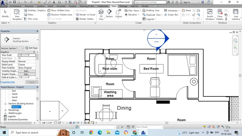
- After placing the section line, go to the section view in the project browser.
- Then select the section view and double click on the view.
- Then the section view will get appear.
- Click the right click for properties and rename the section name as Bed room view.
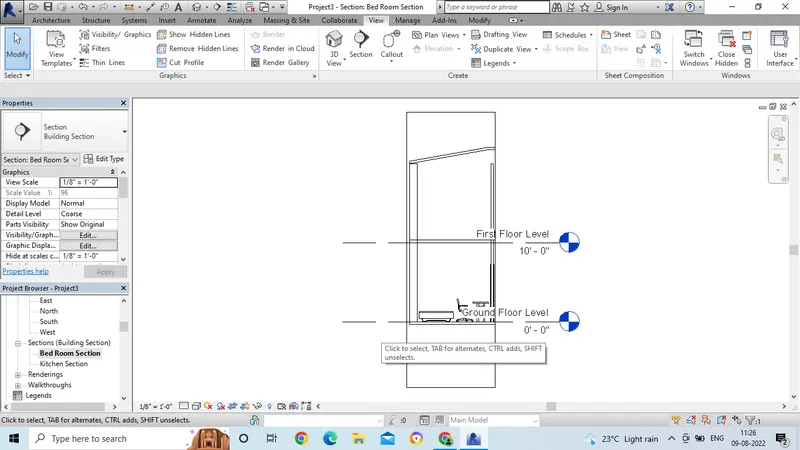
- In the same way, after selecting the section, then draw the tranverse direction line.
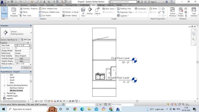
- And again go to the section view, and rename as kitchen.
-
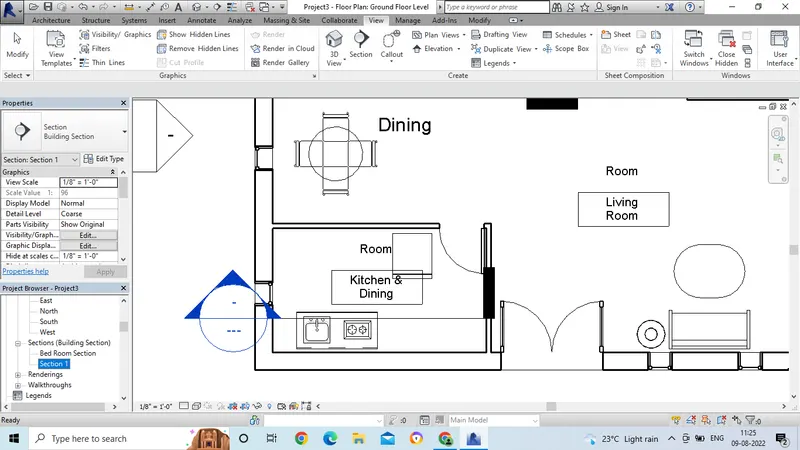
- Now kitchen section view is ready,
- Double click on the name and the section view will get opened.
- In the same way, again take the section line for the living area.
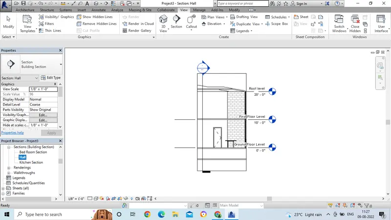
- Go to the project browser and rename the section name.
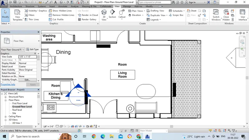
- Then the section view is ready for living area.
Result:
6. Aim: To create the rendering images of the 33D model produced and include in the rendered images to the drawing sheets.
Introduction: To create the rendering images of the 33D model produced and include in the rendered images to the drawing sheets.
Procedure:
- Open the revit software and open the drawing bu usng proper template.
- Now click on the 3D view in the project browser.
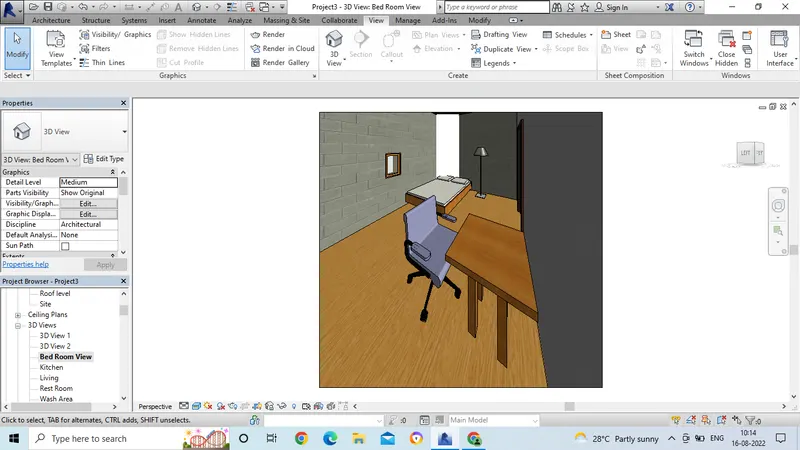
- After taking the 3D image, type RR.
- Then rendering tab will get opened.
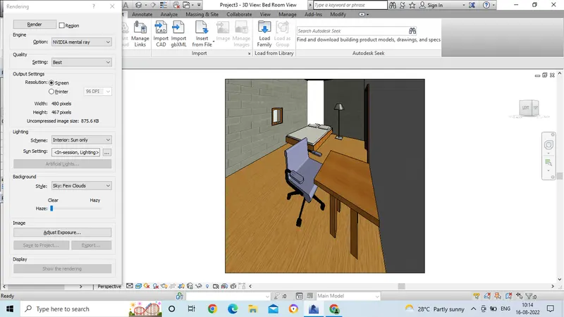
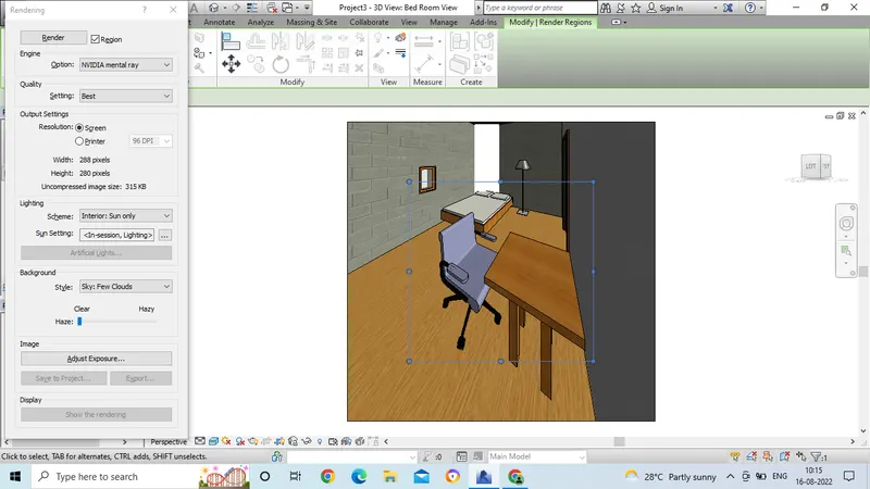
- Then select region.
- And we can see the region line and we have to select the rendering portion from the image.
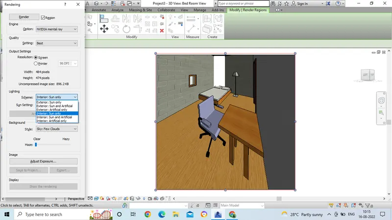
- Then select the scheme in which the sun light has to pass.
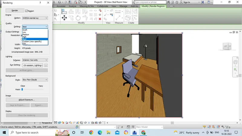
- Now in settings we have to select the quality of image has to get in the rendered image.
- Depends upon the type of the settings we have selected, the rendering of the image time takes place to render.
- Then select the cloudy region for the images.
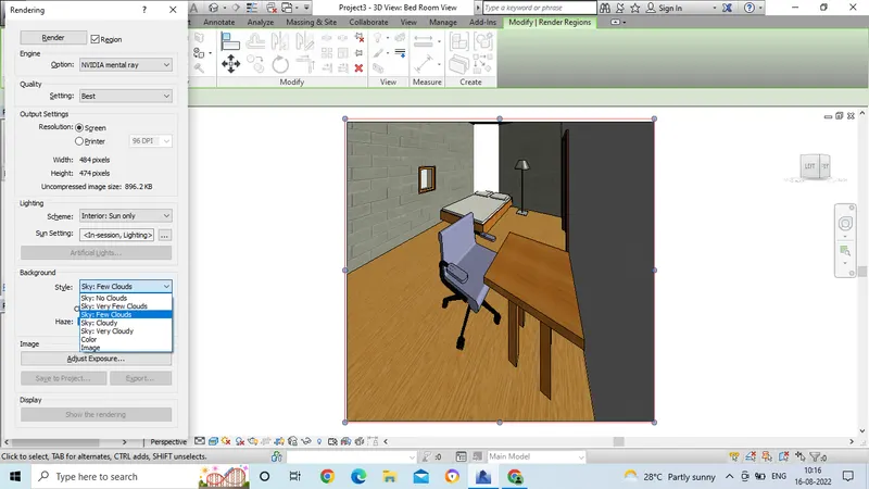
- Then click on Render.
- Now the rendering process for the images has takes place.
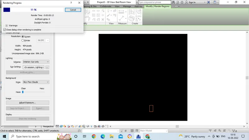
- After rendering process is done, we can see the image.
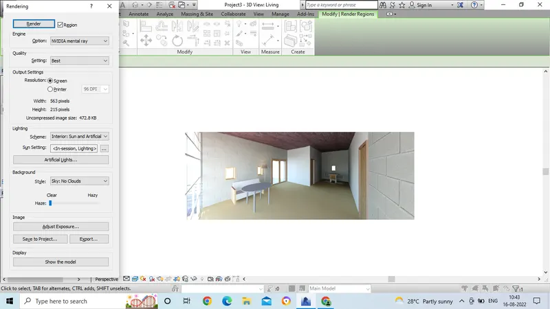
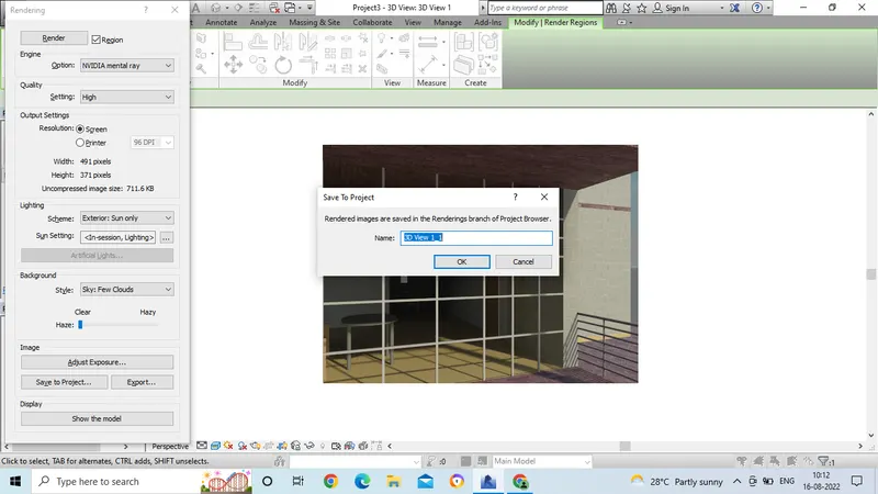
- Now go to the option save project.
- Then we will get the dialogue box to save the image and we can give the name to the rendered image.
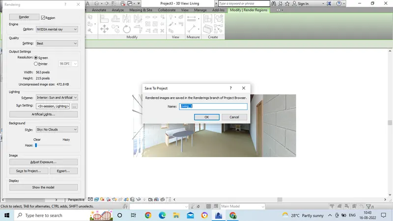
- Then go to the rendering images in the project browser.
- Now double click on the name you have given for the image.
- Then we can see the image which we have created the rendered image.
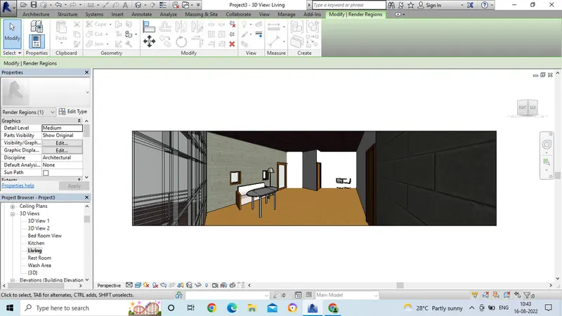
- In the same way do for all the 3d views of the drawings to get the rendered images.
- Now go to the 3d view in the project browser and select the bed room view.
- And start the rendering process in the same way.
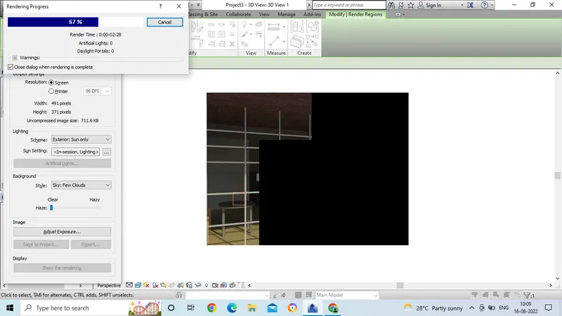
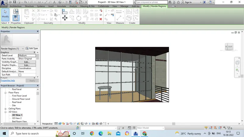
- After rendering we can see the final saved image.
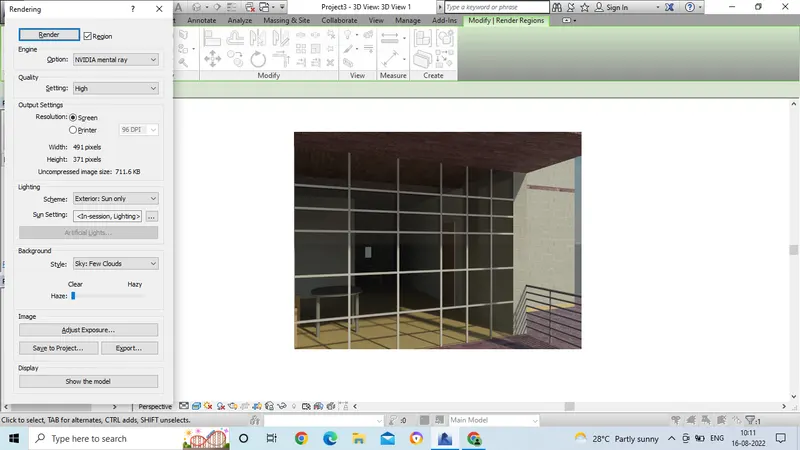
- Then save the image after rendering and this rendered image can be seen in the project browser separately.
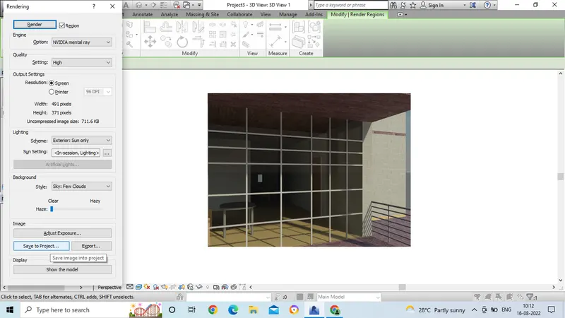
- Then save the image after rendering and this rendered image can be seen in the project browser separately.
- After rendering we can see the final saved image.
Result:
7. Aim: To print the set of drawing sheets created and submit the drawings from the architectural and structural model.
Introduction: To print the set of drawing sheets created and submit the drawings from the architectural and structural model.
Procedure:
- Open the revit software and open the drawing by using proper template.
- Then go to the view tool bar.
- Select the sheet command.
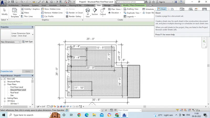
- Now select the paper size in which the drawing is to be placed.
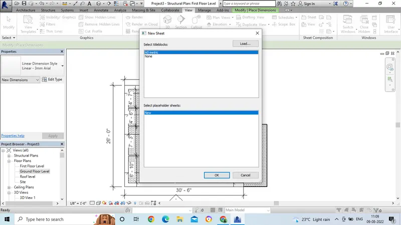
- Then the sheet will get opened.
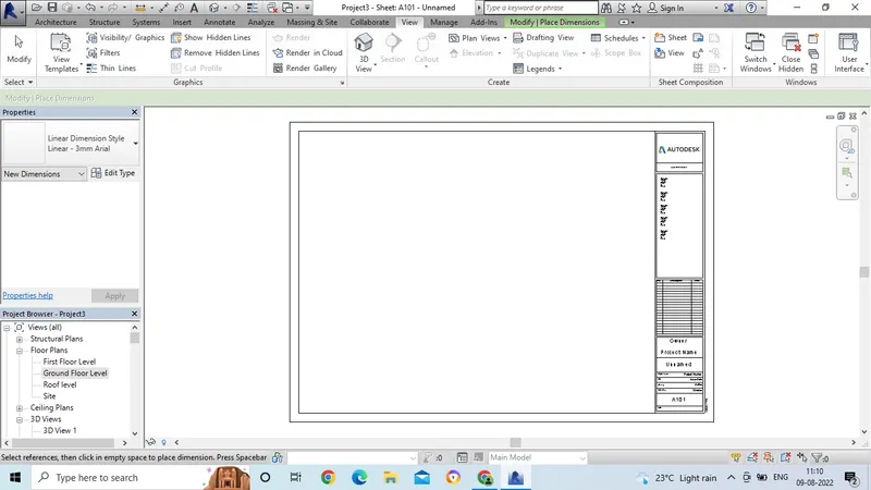
- Now change the information in the sheet by double click on it.
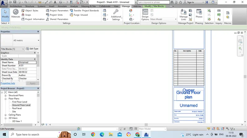
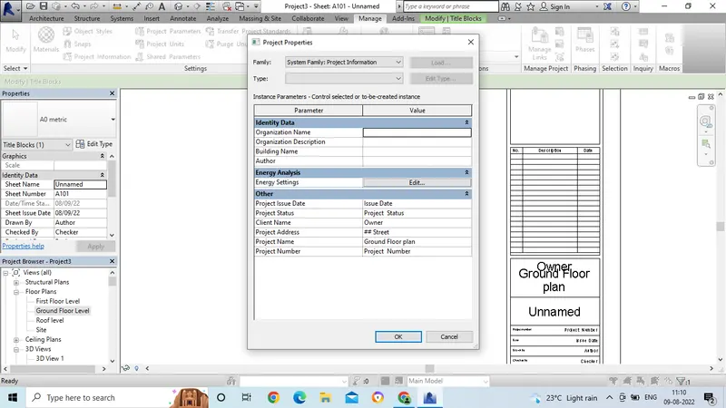
- We can edit the information in the sheet by using project information command.
- Go to the manage tool bar and select the project information.
- Then the dialogue box will get open.
- In that dialogue box, we can give the information which is related to the drawing.
- Then place the drawing in the sheet by selecting from the project browser.
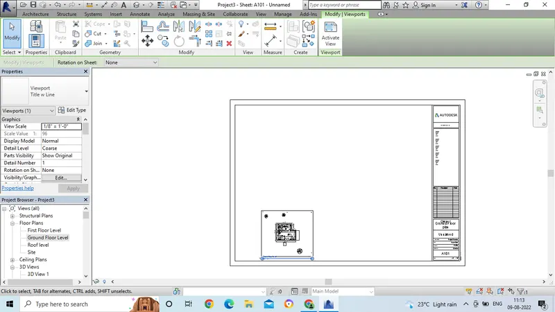
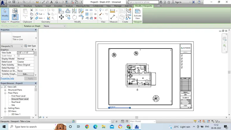
- Select the scale option in the properties bar, to adjust the drawing in the sheet.
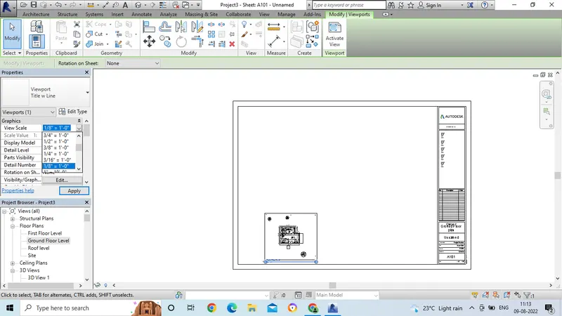
- Now the drawing is adjusted in the sheet.
Result: