Creating Architectural and Structural model with 3D rendering using REVIT
1Q]
The type of Structure I want to build is
Office Building
2Q]
Modelling Requirements for the Office Building as per NBC based on the type of Structure.
Type of Occupancy:
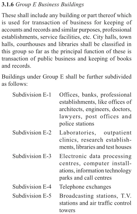
As per NBC part 4 Fire and Life safety
Clause No: 3.1.6
Business Building
Sub division E-3: Information Technology Park
F.A.R:
Type 2 Construction
Allowable FAR:- 2.9
Plot Area: 2695 m2
Total Built up area: 5790 m2
(No of Floors: 6 including Ground Floor)
Calculated F.A.R= 2.15
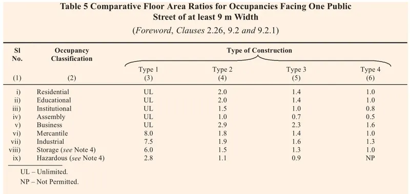
Calculated F.A.R is within the prescribed limits as per NBC
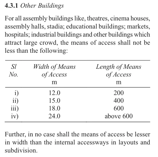
MEANS OF ACCESS:
The Width of Means of access shall not be less than 12 m
SETBACKS:
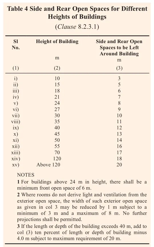
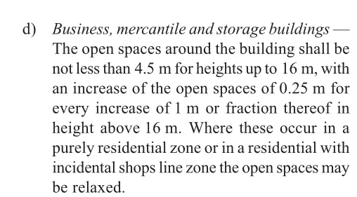
As per Part 3, Development Control Rules and General Building Requirements.
Clause No- 8.2.3.1 and table 4
Heigh of building is 25 m
So, provide side and rear open spaces to be 9m
STAIRCASE:
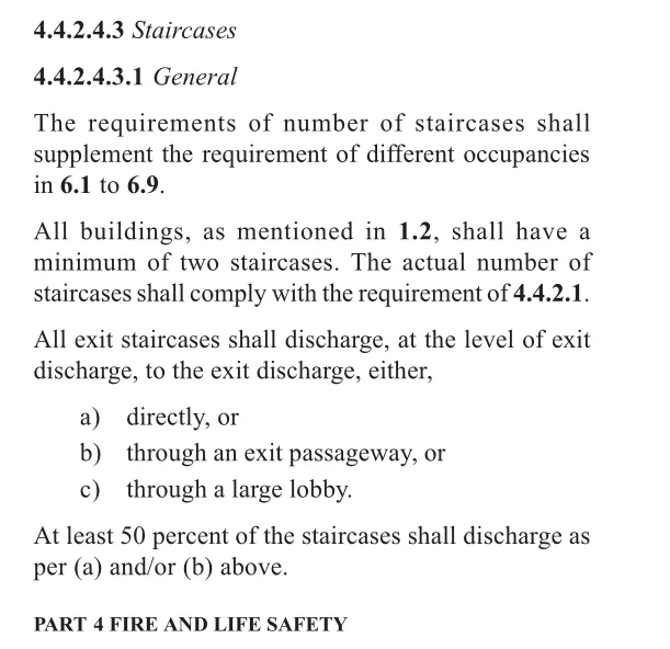
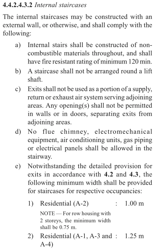
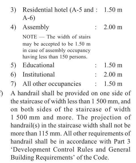
Provide the Stairs as per the Part 4, Fire and Life Safety
The building shall have a minimum of two staircases as mentioned in clause 1.2
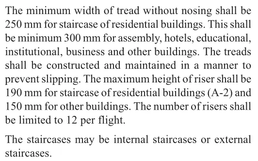
Width of tread: 250mm
Rise of Tread: 150mm
No of Risers per Flight: 12
Width of Staircase: 1.5 m
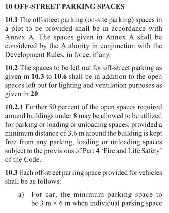
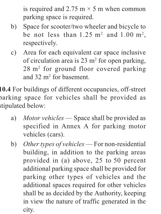
OFF-STREET PARKING SPACES:
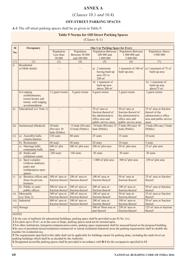
As per Part 3, Development Control Rules and General Building Requirements.
Clause No 10.1 an 10.4
We provided parking space as 300 m2
ARRANGEMENT OF LIFTS:
As per Part 8, Building Services from NBC
Clause 5,
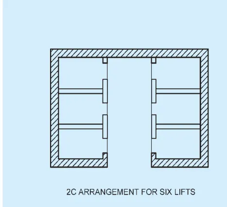
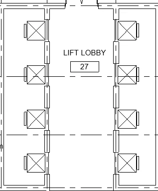
Arrangement of Lifts has to be done in the mentioned way.
FIRE EXTINGUISHERS:
As per Part 4, Table 7
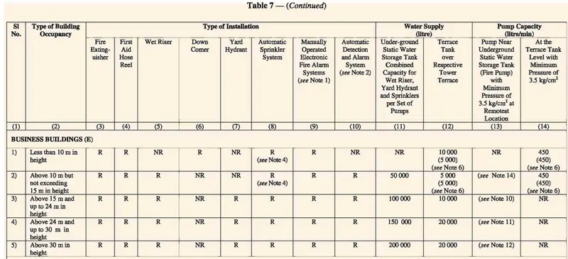
- One ABC powder extinguishers of 6 kgs. Capacity for every 8 cars at parking areas should be provided.
- One CO2 extinguishers of 4.5 kgs. Capacity should be provided near the entrance to the electrical room.
- One Mechanical Foam extinguishers of 9 litres capacity & one ABC powder extinguishers of 6 kgs. Capacity should be provided near the transformer.
- One Mechanical foam extinguishers of 9 litres capacity and one ABC powder extinguishers of 6 kgs. Capacity should be provided near the diesel generator.
- One CO2 extinguishers of 2 kgs. Capacity should be provided inside each lift machine room.
- One Water Mist type extinguishers of 4 litres & 9 litres capacity should be kept near each staircase landing at each floor.
3Q]
AIM: -
Create New Structural project using Structure Template
Set the Project Base Point
Copy Grids from the Architectural Plan to Structural plan.
Create the Following components for the selected structure
- Foundation
- Columns
- Beams connected to Columns
- Floor
- Floor Opening
- Roof Framing/Truss
PROCEDURE: -
Open the Revit software
Click on NEW
New Project dialogue box opens
Select Structural Template
Create: New Project
Press OK
Click on STRUCTURAL Tab
Go to Datum panel
Select Grid

Choose Line from the Draw panel
Draw Horizontal line on the model space and edit the name to “A”
Draw Vertical line intersecting the Horizontal line and name it as “1”
Click on MANAGE TAB
Go to Project Location panel
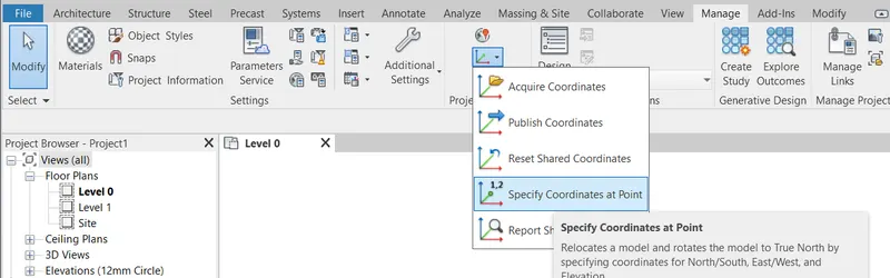
Select Coordinates tool and Choose Specify Coordinates at point option
Click on Grid line “1”
Specify Shared Coordinates dialogue box opens
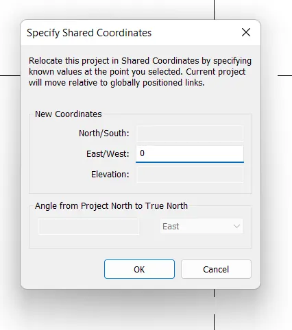
Set New Coordinates
East/West: 0
Press OK
Select Coordinates tool and Choose Specify Coordinates at point option
Click on Grid line “A”
Specify Shared Coordinates dialogue box opens
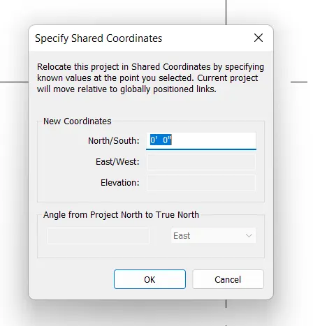
Set New Coordinates
North/South: 0
Press OK
Type VG
Visibility Graphics dialogue box opens.
Select SITE and Expand the list
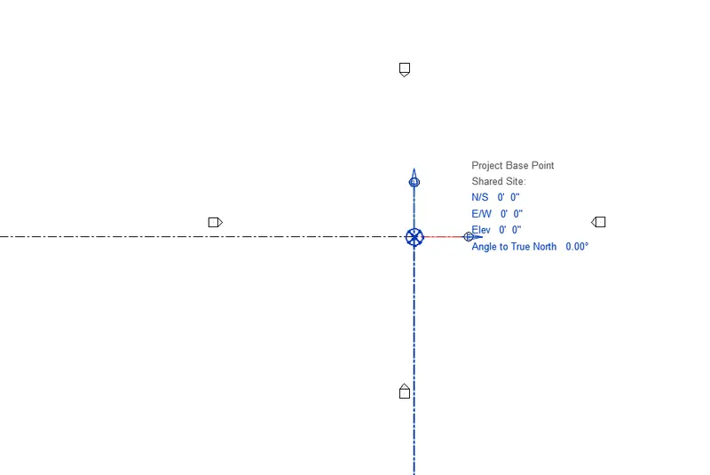
Tick on Project base Point
Click on Apply and Press OK
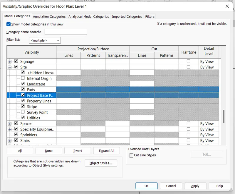
Base point appears on the model space.
Set the Base Point at the Intersection of Gridlines.
Click on INSERT TAB
Go to LINK panel
Choose Link Revit tool
Import/Link RVT dialogue box opens
Select the Architectural File in which we drawn Gridlines.
Click on OPEN
Architectural File is imported to the Structural File.
It is not copied to the Structural File.
To Check whether the file is imported or copied,
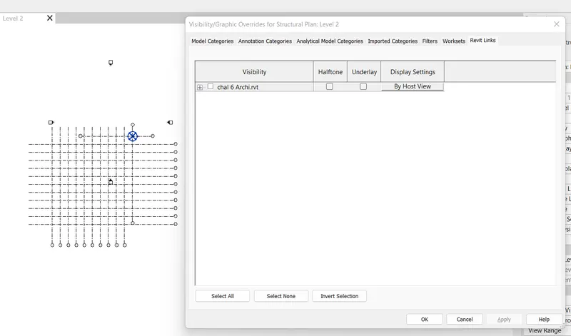
Type VG
Visibility graphics dialogue box opens
Select Revit Links Tab
Untick on the Imported file.
Press Apply
The Gridlines disappears from the Model space.
Now we have to copy these Gridlines to the structural file.
For that, Select COLLABORATE TAB
Go to Coordinate panel
Click on Copy/Monitor

Choose Select Link from the dropdown list
Click on the Link on the model space
Select COPY tool in the Ribbon tab
Tick on Multiple option
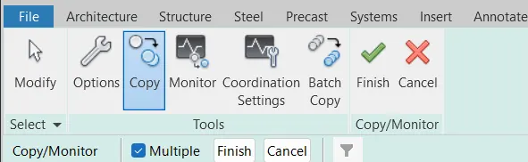
Select all the Gridlines in the Model space which are imported from the Architecture file.
Click on Finish then Click on COPY/MONITOR in the Ribbon tab.
Click on finish icon.
Now, The Gridlines are copied to the Structural File.
To Check whether the file is imported or copied,
Type VG
Visibility graphics dialogue box opens
Select Revit Links Tab
Untick on the Imported file.
Press Apply
Now Gridlines won’t disappear from the model space.
So, the Gridlines are copied to the Structural File.
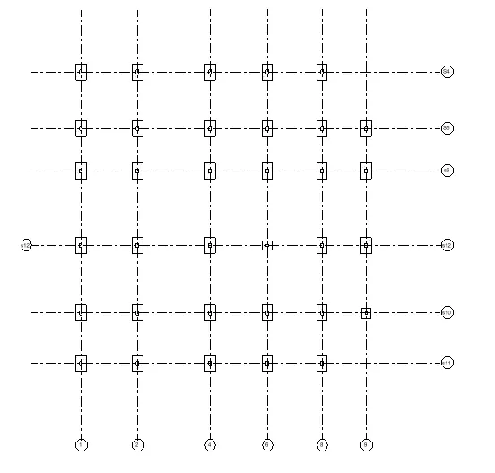
FOUNDATION: -
Select Structure Tab
Go to Foundation panel
Click on Isolated Footing tool

Go to PROPERTIES Browser
Select the appropriate Footing Type
Click on Edit type
Edit the sizes of footing if required
Press Apply

Choose at Grids option in Modify Tab
Footings are created at Grids.
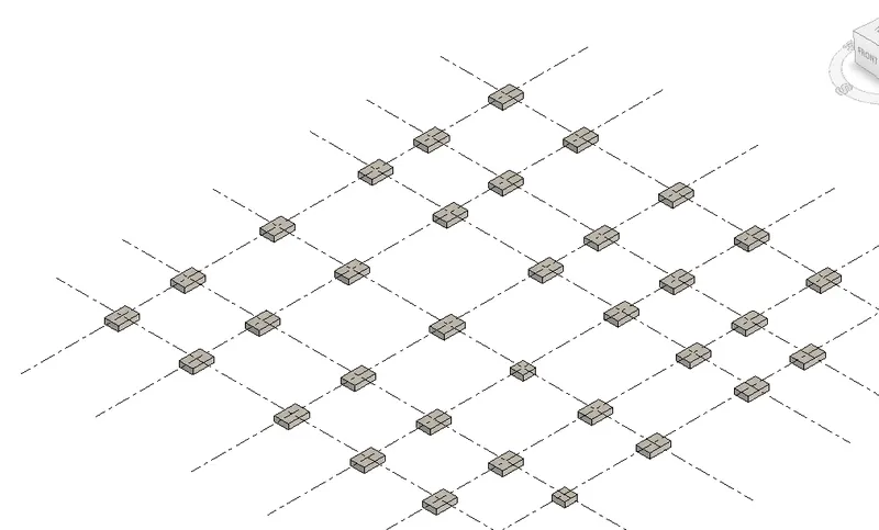
COLUMNS: -
Select Structure Tab
Go to Structure panel
Click on Column
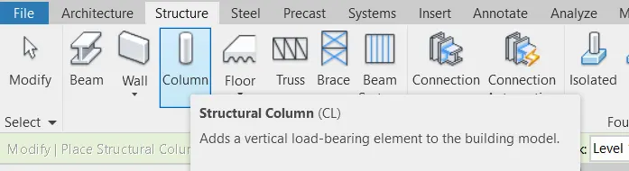
Go to PROPERTIES Browser
Select the appropriate Column Type
\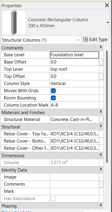
Click on Edit type
Edit the sizes of Column if required
Press Apply

Choose at Grids option in Modify Tab
Columns are created at Grids.
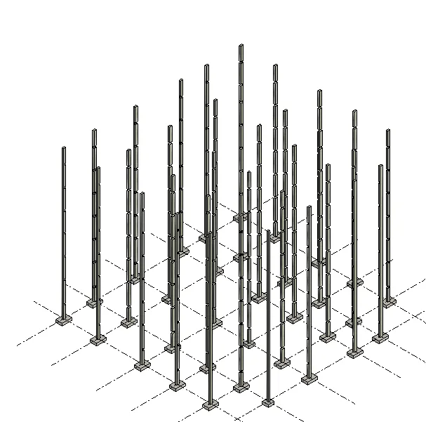
BEAMS: -
Select Structure Tab
Go to Structure panel
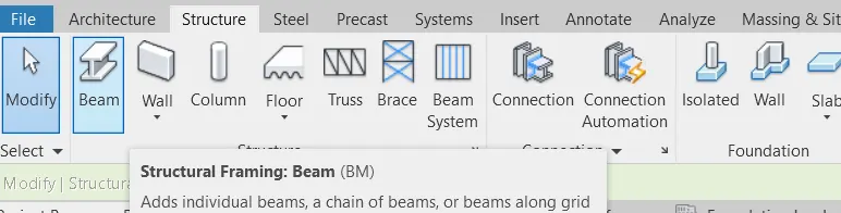
Click on BEAMS
Go to PROPERTIES Browser
Select the appropriate BEAM Type
Click on Edit type
Edit the sizes of BEAM if required
Press Apply
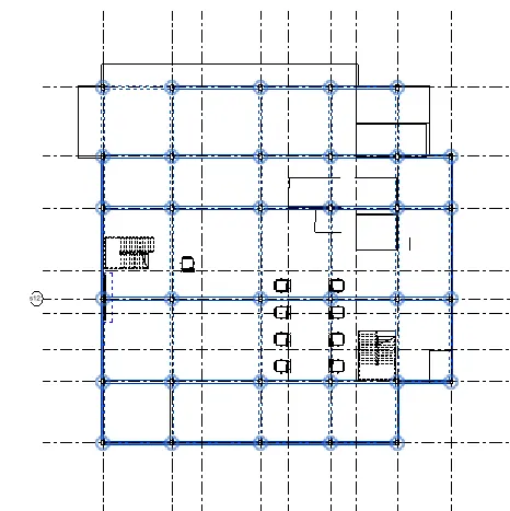
Choose at Grids option in Modify Tab
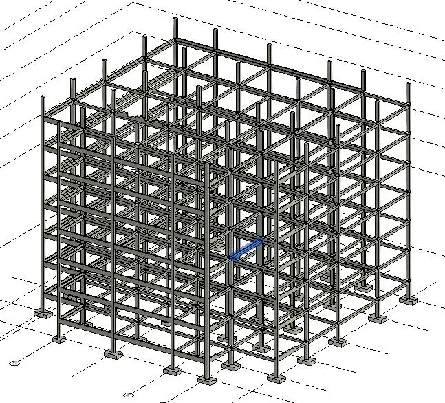
BEAMS are created on Grids.
Repeat the same procedure for all Levels.
FLOOR: -
Select Structure Tab
Go to Structure panel
Click on FLOOR
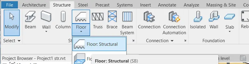
Choose Structural floor from the dropdown list
Go to PROPERTIES Browser
Select the appropriate Floor Type
Click on Edit type
Change the material if required.
Press Apply
Create Floor Boundary

Floor is created
Select the Floor on the model space
Choose Copy to Clipboard tool in Modify Tab
Click on Paste Tool
Choose Aligned to selected levels from the dropdown list
Select Levels dialogue box opens
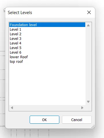
Select all the Required levels
Press OK
Floor is created in all levels.
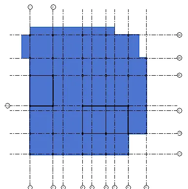
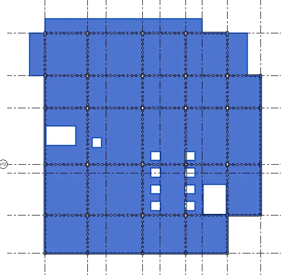
FLOOR OPENINGS FOR STAIRS AND ELEVATORS: -
Select ARCHITECTURE Tab
Go to Opening panel
Click on SHAFT

Go to PROPERTIES Browser
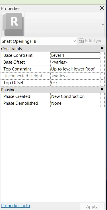
Change the Base Constraint
Change the Top constraint
Press Apply
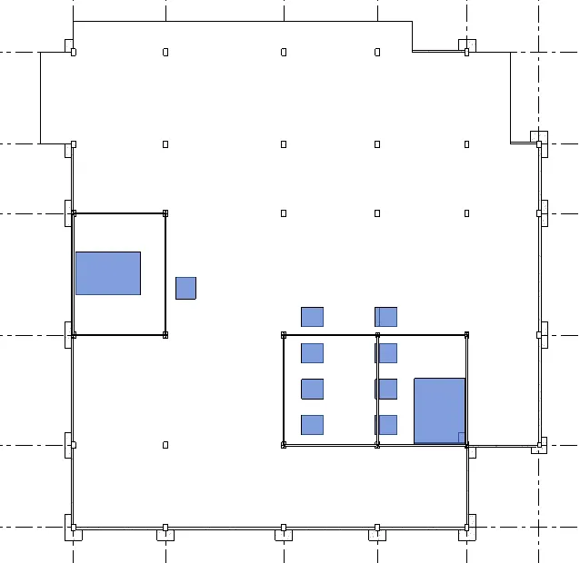
Choose appropriate tool from the Draw panel and create Shaft opening

Opening is created for Stairs and Elevators.
ROOF FRAMING/TRUSS: -
Select Structure Tab
Go to Structure panel
Click on TRUSS
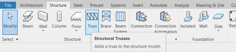
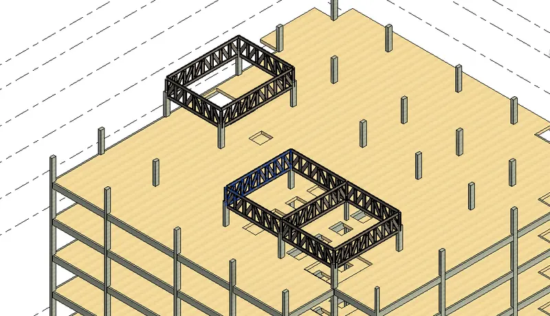
Choose Pick lines option in Modify Tab
Pick the lines or draw the lines wherever required.

Trusses are created
Go to PROPERTIES Browser
Change the Base Offset
Change the Top Offset
Press Apply
RESULT: -
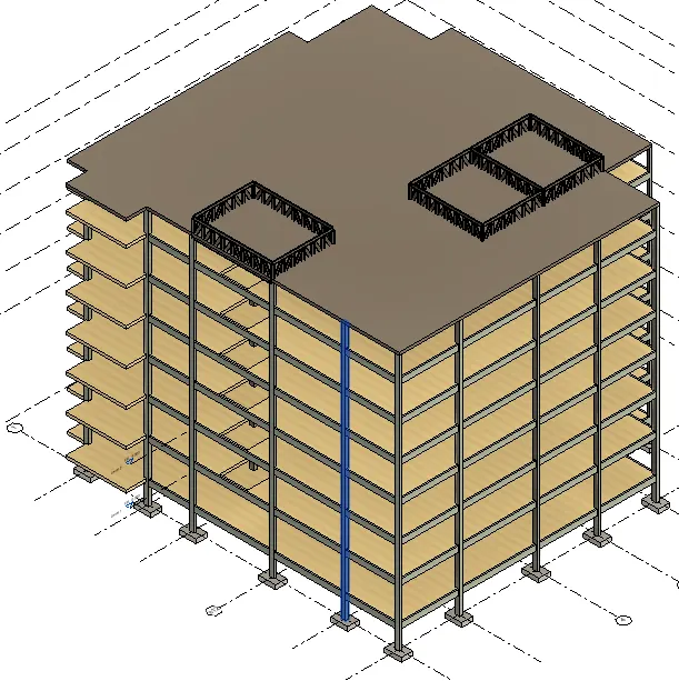
We created New Structural project using Structure Template.
Set the Project Base Point
Copied Grids from the Architectural Plan to Structural plan using Copy/Monitor command
Created the Following components for the selected structure
- Foundation
- Columns
- Beams connected to Columns
- Floor
- Floor Opening
- Roof Framing/Truss
4Q]
AIM: -
For the Selected structure, using the Architectural model create the following components:
- Wall Layout with appropriate material and finishing
- Exterior façade with fancy finish
- Interior Partition walls to size rooms
- Components to add details to a room like Desk, chair, Lighting, Plumbing fixtures
- Add components such as stairs and Elevators
- Have at-least one side of the building with curtain walls and Glass panels
- Include interior and exterior Lighting fixtures
- Place proper topographic components from outside ( trees, parking, plants) to add details to the model.
PROCEDURE: -
Open the REVIT software
Click on NEW
New Project dialogue box opens
Select one of the Template File: Architectural Template
Select one of the options in Create new: PROJECT
Press OK
Create Folder Name REVIT on desktop
After opening of the Template
Select FILE TAB
Choose Save
Save in: Desktop > REVIT
File Name: SAMPLE
Press SAVE
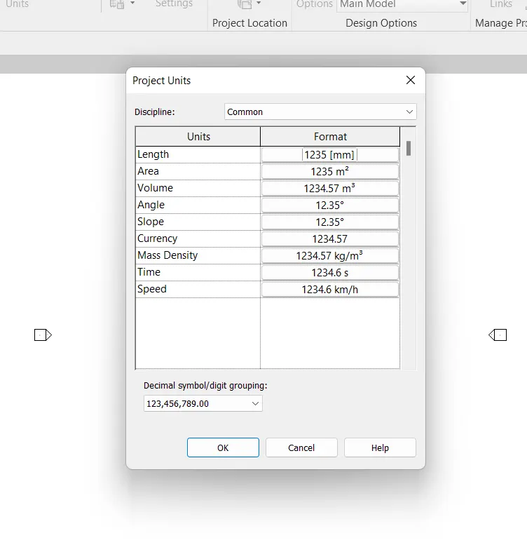
Select the MANAGE TOOLBAR
Go to Settings
Choose PROJECT UNITS icon
Change the LENGTH Format to mm
Press OK
Select the MANAGE TOOLBAR
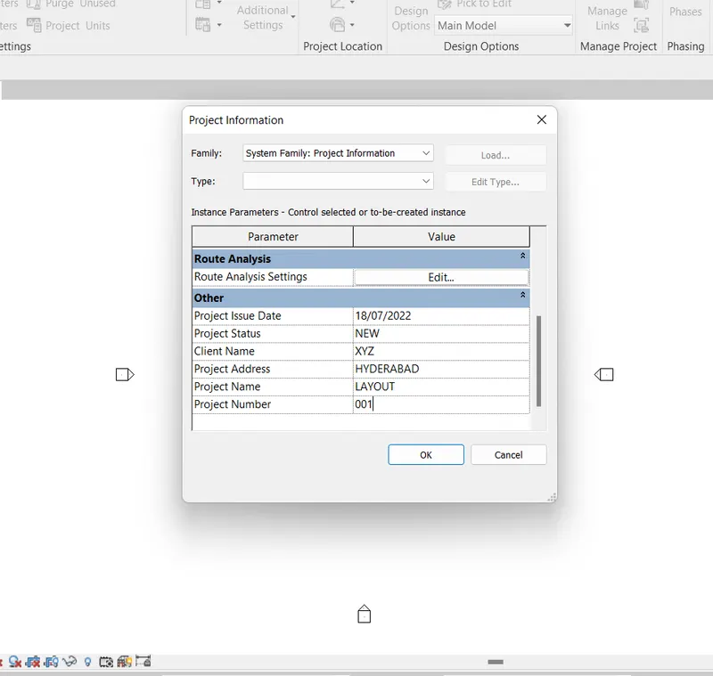
Go to Settings
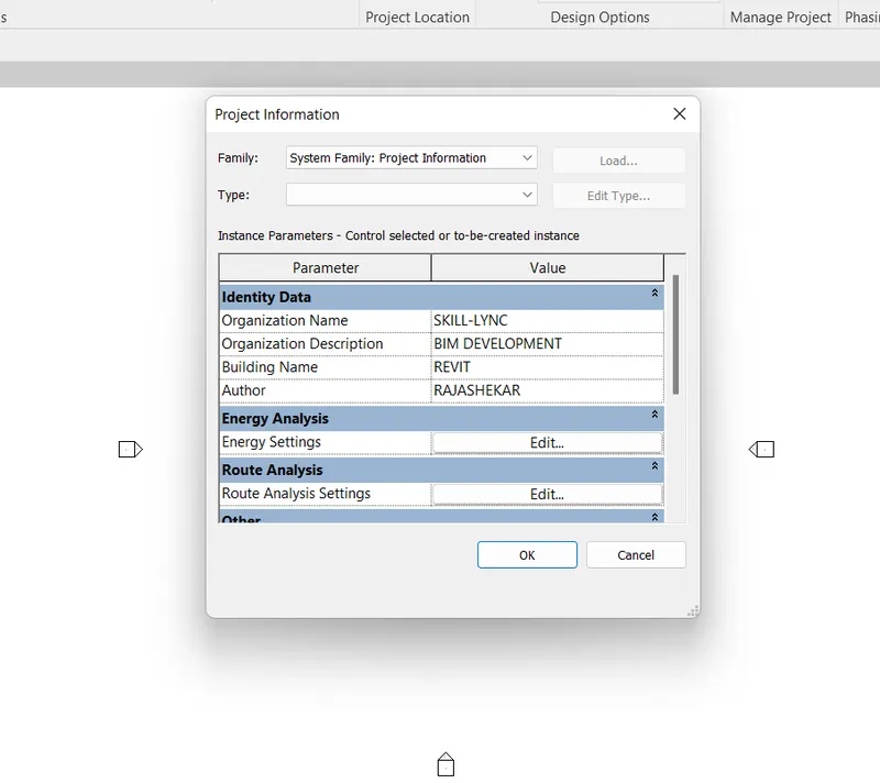
Choose PROJECT information icon
Enter the data
Organisation Name:
Organisation Description:
Building Name:
Author:
Project issue Date:
Project Status:
Client Name:
Project Address:
Project Name:
Project number:
Press OK
Select FILE TAB
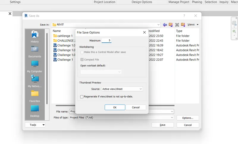
Choose Save as
Select options
File Save options dialogue box opens
Enter the value for Maximum backups: 5
Press OK
Press SAVE
Select Architecture Tab
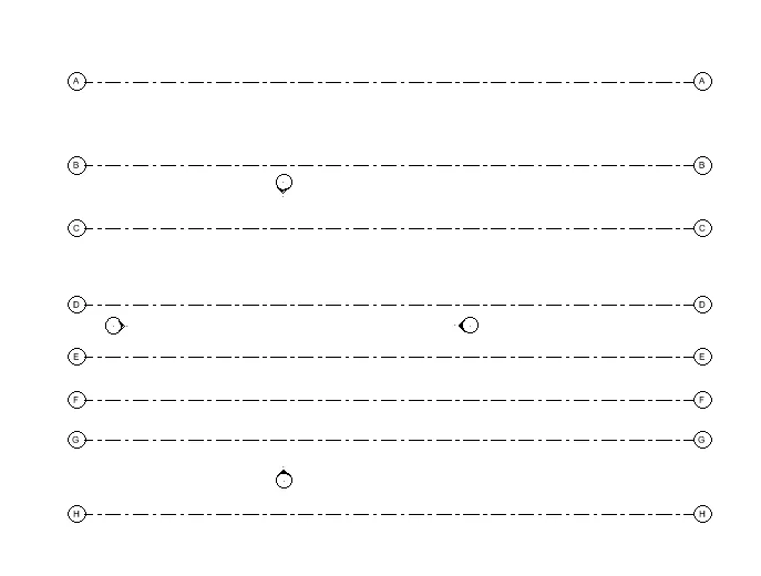
Go to DATUM panel and select GRIDS tool
Select Lines from Draw panel
Draw a Transverse line of certain distance
Move the cursor to the Text
Click on the Text and change the value to A
Grid line A is created
Draw the Transverse Gridlines from Top to Bottom.
Go to DATUM panel and select GRIDS tool
Select Pick Lines from Draw panel
Mention Offset distance: 6400 mm
Select the 1st Grid line and Show the direction below the Grid line A
Grid line B is created with offset distance of 6400 mm from A
Select the Grid line and Show the direction below the Grid line B
Grid line C is created with offset distance of 4800 mm from B
Select the Grid line and Show the direction below the Grid line C
Grid line D is created with offset distance of 5800 mm from C
Select the Grid line and Show the direction below the Grid line D
Grid line E is created with offset distance of 4000 mm from D
Select the Grid line and Show the direction below the Grid line E
Grid line F is created with offset distance of 3300 mm from E
Select the Grid line and Show the direction below the Grid line F
Grid line G is created with offset distance of 3000 mm from F
Select the Grid line and Show the direction below the Grid line G
Grid line H is created with offset distance of 5700 mm from G
Go to DATUM panel and select GRIDS tool
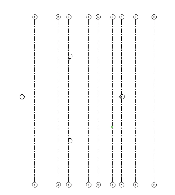
Select Lines from Draw panel
Draw a Longitudinal line of certain distance on above the Transverse Grid lines.
Move the cursor to the Text
Click on the Text and change the value to 9
Grid line 9 is created
Draw the Longitudinal Grid Lines from Right to Left
Go to DATUM panel and select GRIDS tool
Select Pick Lines from Draw panel
Mention Offset distance: 5000 mm
Select the 1st Grid line and Show the direction to left of the Grid line 9
Grid line 8 is created
Select the 2nd Grid line and Show the direction to left of the Grid line 8
Mention Offset distance: 2800 mm
Grid line 7 is created
Select the 3rd Grid line and Show the direction to left of the Grid line 7
Mention Offset distance: 2400 mm
Grid line 6 is created
Select the 4th Grid line and Show the direction to left of the Grid line 6
Mention Offset distance: 3900 mm
Grid line 5 is created
Select the 5th Grid line and Show the direction to left of the Grid line 5
Mention Offset distance: 2600 mm
Grid line 4 is created
Select the 6th Grid line and Show the direction to left of the Grid line 4
Mention Offset distance: 5400 mm
Grid line 3 is created
Select the 7th Grid line and Show the direction to left of the Grid line 3
Mention Offset distance: 2800 mm
Grid line 2 is created
Select the 8th Grid line and Show the direction to left of the Grid line 2
Mention Offset distance: 6400 mm
Grid line 1 is created
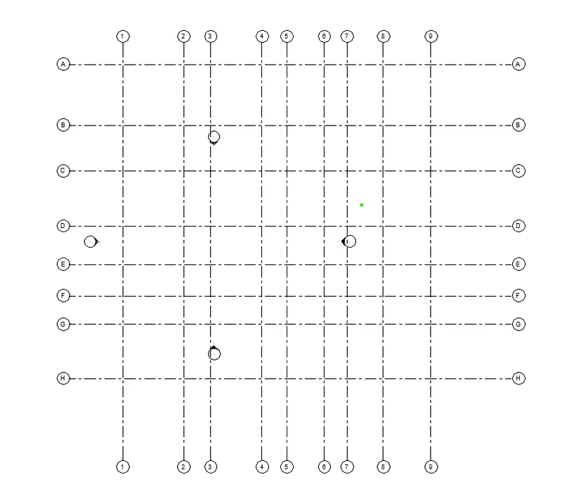
Select Architecture Tool bar.
Right click on the Model space
Go to the Browser and select one of the options Project Browser from the dropdown list.
In Project Browser column
Go to Elevations column and select SOUTH
By default, 2 levels are visible.
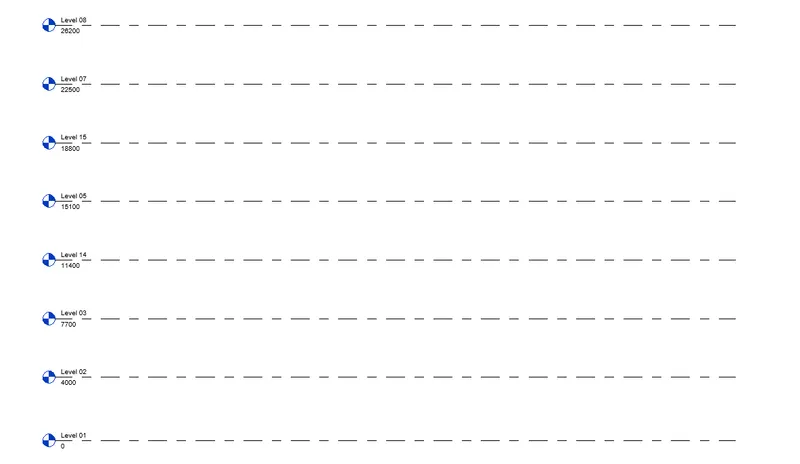
Level 1 and Level 2
Move the Cursor to Level 1 Text
Click on the text and change the text to Ground Floor
Move the cursor to Level 1 value
click on the value and change the value to 4000 units.
Move the Cursor to Level 2 Text
Click on the text and change the text to First Floor
Move the cursor to Level 2 value
click on the value and change the value to 3700 units.
In Architecture Tab
Go to DATUM panel and select LEVEL tool
Select Pick lines from Draw panel
Mention the OFFSET distance: 3700 mm
Select the First Floor Level and show the Direction for offset above the First Floor
Now we created Level 3 with value 7700 mm
Go to DATUM panel and select LEVEL tool
Select Pick lines from Draw panel
Mention the OFFSET distance: 3700 mm
Select the Level 3 and show the Direction for offset above the Level 3
Now we created Level 4 with value 11400 units.
Go to DATUM panel and select LEVEL tool
Select Pick lines from Draw panel
Mention the OFFSET distance: 3700 mm
Select the Level 4 and show the Direction for offset above the Level 4
Now we created Level 5 with value 15100 units.
Go to DATUM panel and select LEVEL tool
Select Pick lines from Draw panel
Mention the OFFSET distance: 3700 mm
Select the Level 5 and show the Direction for offset above the Level 5
Now we created Level 6 with value 18800 units.
Go to DATUM panel and select LEVEL tool
Select Pick lines from Draw panel
Mention the OFFSET distance: 3700 mm
Select the Level 6 and show the Direction for offset above the Level 6
Now we created Level 7 with value 22500 units.
Go to DATUM panel and select LEVEL tool
Select Pick lines from Draw panel
Mention the OFFSET distance: 3700 mm
Select the Level 7 and show the Direction for offset above the Level 7
Now we created Level 8 with value 25000 units.
EXTERIOR WALLS: -
Select ARCHITECTURE Tab
Go to BUILD panel and choose WALL tool.
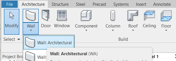
Choose the LOCATION LINE as per the requirement from the list.
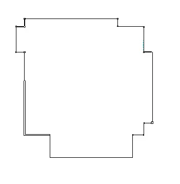
Draw OUTER WALLS
Go to PROPERTIES BROWSER
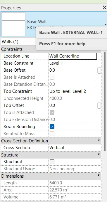
Change the properties of the wall
Click on EDIT TYPE
Type Properties dialogue box opens
Click on Duplicate
Change Name: - External wall 300 mm
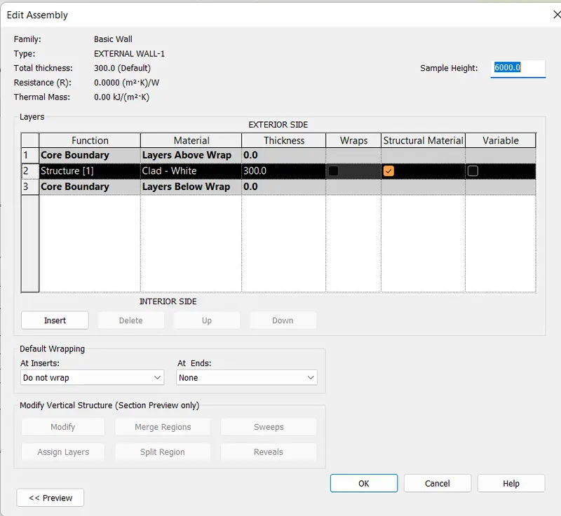
Select parameter STRUCTURE and click on edit
Change the thickness to 300 units.
Material: Clad White
Press OK.
Select ARCHITECTURE Tab
Go to BUILD panel and choose WALL tool.
Choose the LOCATION LINE as per the requirement from the list.
Draw INTERIOR WALLS
Go to PROPERTIES BROWSER
Change the properties of the wall
Click on EDIT TYPE
Type Properties dialogue box opens
Click on Duplicate
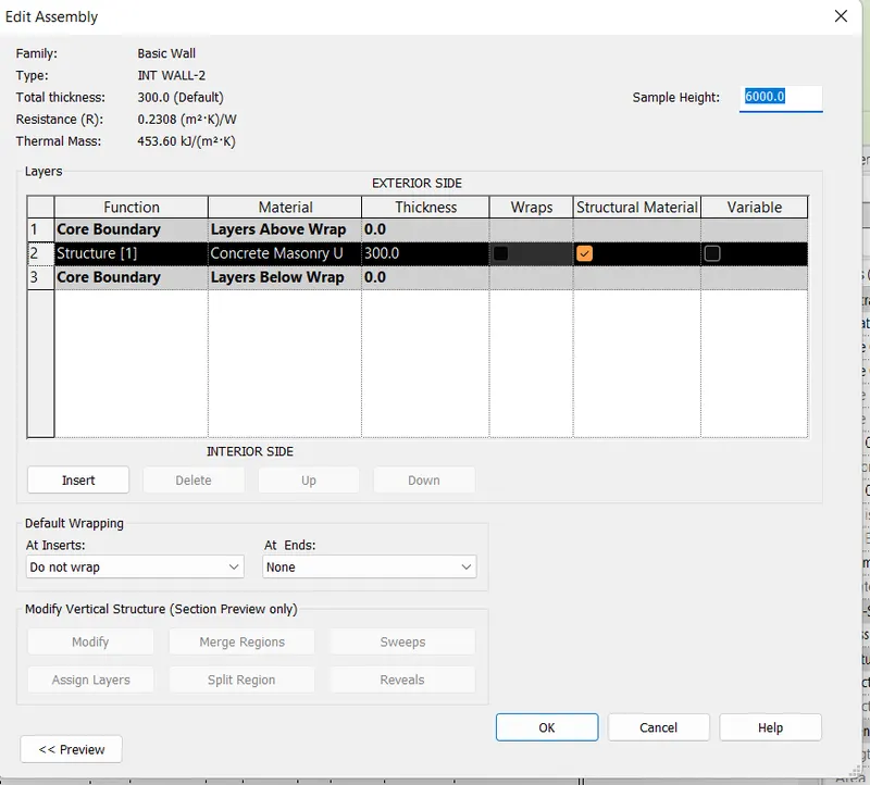
Change Name: - Int walls 2-300 mm
Select parameter STRUCTURE and click on edit
Change the thickness to 300 units.
Material: Concrete Masonry Units.
Press OK.
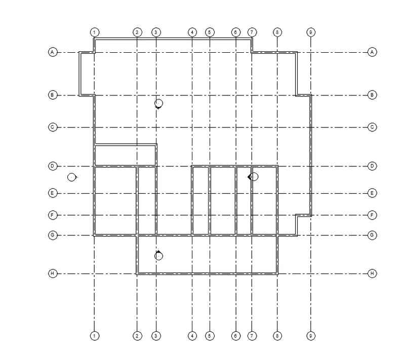
Draw Rooms using this wall
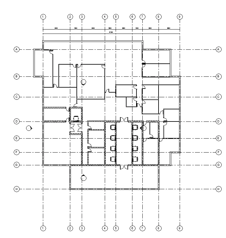
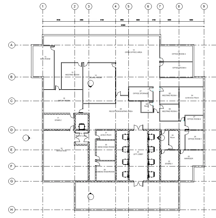
Lift Lobby – 8900 x 10450
Stairs 1 – 3800 x 6300
Stairs 2 – 3800 x 6300
Service Lobby – 2800 x 6250
Prayer Room – 2060 x 4000
Select ARCHITECTURE Tab
Go to BUILD panel and choose WALL tool.
Choose the LOCATION LINE as per the requirement from the list.
Draw INTERIOR WALLS
Go to PROPERTIES BROWSER
Change the properties of the wall
Click on EDIT TYPE
Type Properties dialogue box opens
Click on Duplicate
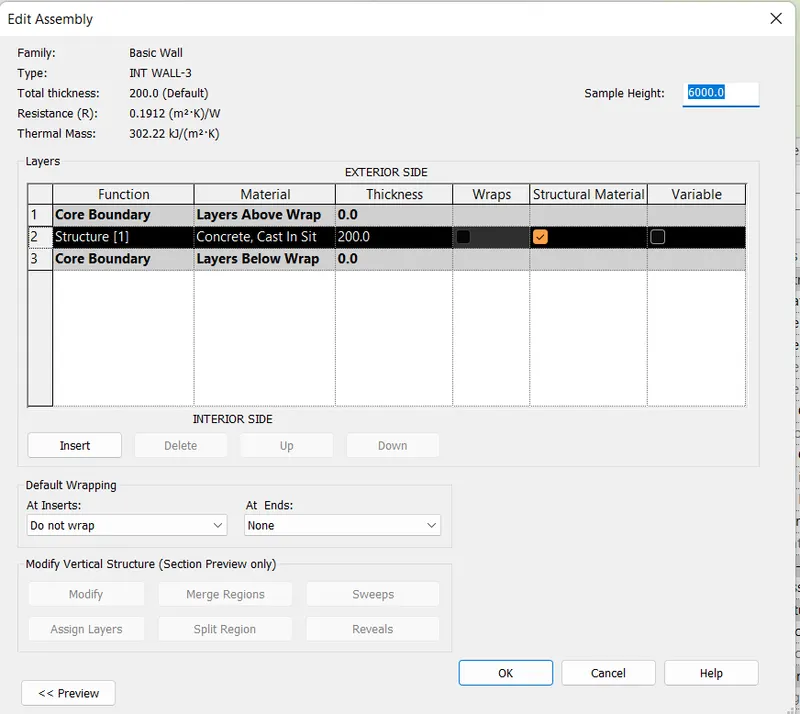
Change Name: - Int Walls 3 - 200 mm
Select parameter STRUCTURE and click on edit
Change the thickness to 200 units.
Material: Concrete, Cast in Situ
Press OK.
Draw Rooms using the wall.
Women Wash Room – 4000 x 4150
Gents Wash Room – 4000 x 4150
Janitors Room – 4000 x 2050
CCTV Room – 5600 x 2500
Security – 5250 x 2500
Select ARCHITECTURE Tab
Go to BUILD panel and choose WALL tool.
Choose the LOCATION LINE as per the requirement from the list.
Draw INTERIOR WALLS
Go to PROPERTIES BROWSER
Change the properties of the wall
Click on EDIT TYPE
Type Properties dialogue box opens
Click on Duplicate
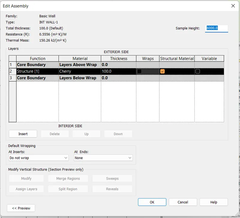
Change Name: - Int walls 100 mm
Select parameter STRUCTURE and click on edit
Change the thickness to 100 units.
Material: Cherry
Press OK.
Create Rooms using Interior walls
Building Lobby – 20900 x 5700
Service Area – 9200 x10300
Office Room 1 – 3800 x 3950
Office Room 2 – 3800 x 3950
Office Room 3 – 6700 x 3350
Office Room 4 – 6700 x 3350
Reception/Waiting Area
Meeting Room 1 – 3900 x 3475
Meeting Room 2 – 3900 x 3475
Meeting Room 3 – 4300 x 5400
Conference Room – 5000 x 5700
Idea Room – 6360 x 4450 units
Board Room - 8100 x 6500 units
Open Office Area
Break Room – 8000 x 4850
COMPONENTS TO ADD DETAILS TO A ROOM: -
Select INSERT tab
Go to Load From Library panel and click on Load Autodesk Family tool
Load Autodesk Family dialogue box opens
Select plumbing in browser
Go to Architectural tab
Go to Fixtures tab
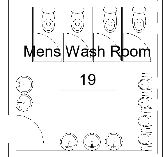
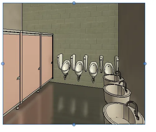
Choose plumbing fixtures Cubicles assembly 4
Choose Urinal (2)
Choose Urinal Screen (1)
Choose sink vanity Round basin
Choose plumbing Fixtures Counter top with Sink
Press Load
We added Sink, Toilet cubicles, Urinals, Water Closet
Select ARCHITECTURE tab.
Go to BUILD panel and click on Component tool and select Place a component option
Place the components in the Men’s Washroom and Women’s Washroom
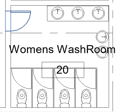
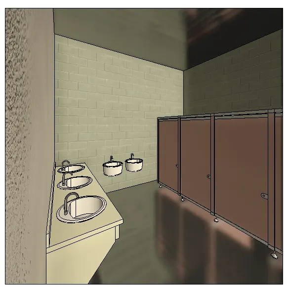
Select INSERT tab
Go to Load From Library panel and click on Load Autodesk Family tool
Load Autodesk Family dialogue box opens
Select Speciality Equipment in browser
Choose Speciality_Equipment_Place_standard
Choose Speciality_Equipment_Cup_w_saucer Cutlery_China_saucer
Choose Speciality_Equipment_wine bottle_wine-Red
Press Load
Select INSERT tab
Go to Load From Library panel and click on Load Autodesk Family tool
Load Autodesk Family dialogue box opens
Select Furniture in browser
Choose Furniture table with Chairs_Rectangular
Choose Furniture_Cresent Sofa
Choose Furniture_Coffee_Table2
Press Load
Select ARCHITECTURE tab.
Go to BUILD panel and click on Component tool and select Place a component option
Place the components in the Break Room
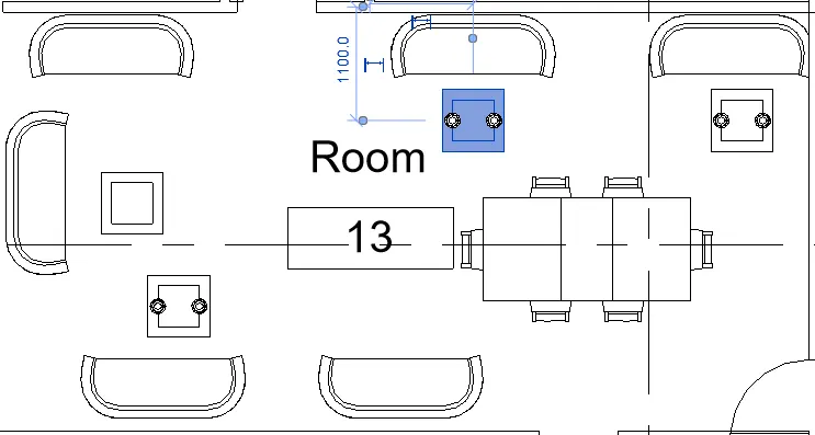
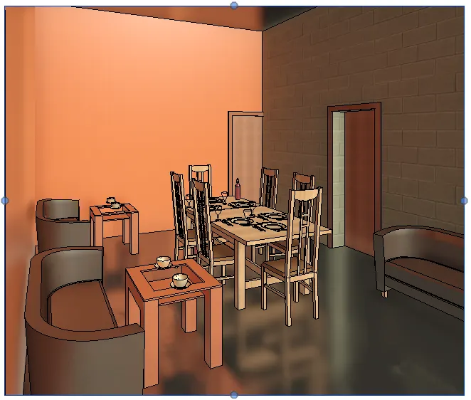
Select INSERT tab
Go to Load From Library panel and click on Load Autodesk Family tool
Load Autodesk Family dialogue box opens
Select Furniture in browser
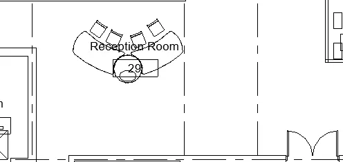
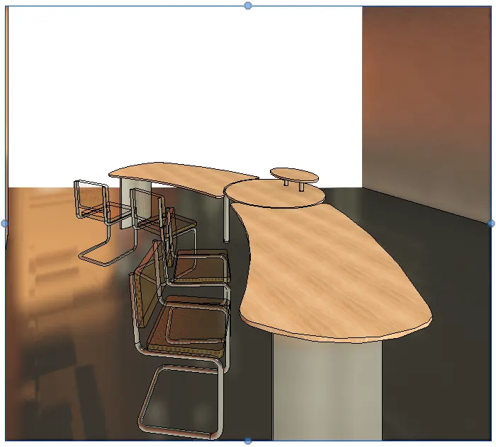
Choose Furniture_desk_reception
Choose M_chair_breuer
Press Load
Select ARCHITECTURE tab.
Go to BUILD panel and click on Component tool and select Place a component option
Place the components in the Reception room
Select INSERT tab
Go to Load From Library panel and click on Load Autodesk Family tool
Load Autodesk Family dialogue box opens
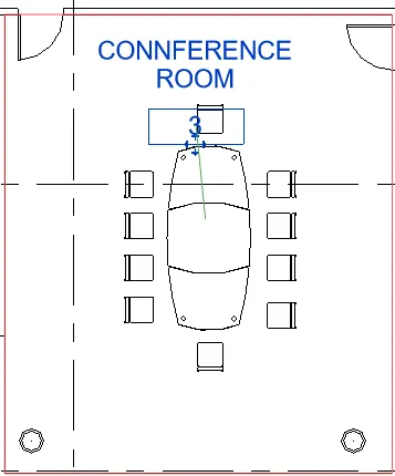
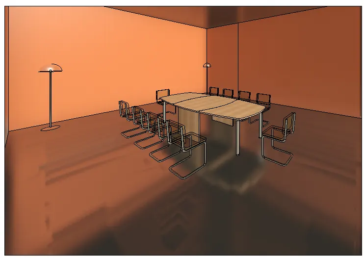
Choose Furniture_Table_Meeting_large
Choose M_chair_breuer
Press Load
Select ARCHITECTURE tab.
Go to BUILD panel and click on Component tool and select Place a component option
Place the components in the CONFERENCE ROOM
Select INSERT tab
Go to Load From Library panel and click on Load Autodesk Family tool
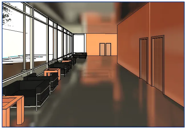
Load Autodesk Family dialogue box opens
Choose M_Chair_Corbu
Choose M_Sofa_Corbu
Choose Furtniture_Table_coffee2
Press Load
Select ARCHITECTURE tab.
Go to BUILD panel and click on Component tool and select Place a component option
Place the components in the Building Lobby

Select INSERT tab
Go to Load From Library panel and click on Load Autodesk Family tool
Load Autodesk Family dialogue box opens
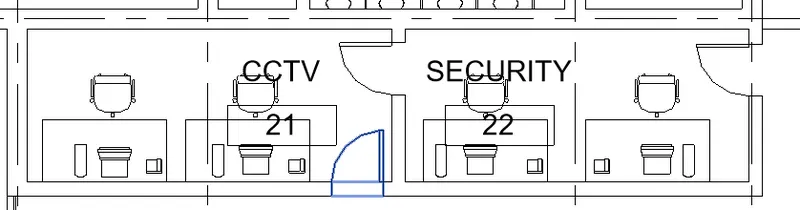
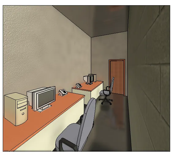
Choose M_Desk1
Choose M_Chair_Executive
Choose Speciality_Equipment_Monitor 17”
Choose Speciality_Equipment_CPU
Choose Speciality_Equipment_phone
Press Load
Select ARCHITECTURE tab.
Go to BUILD panel and click on Component tool and select Place a component option
Place the components in the Security and CCTV room.
STAIRS AND ELEVATORS: -
Select Architectural tab
Go to Circulation panel
Choose Stairs

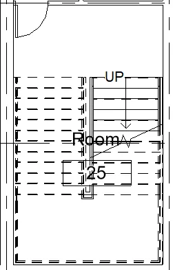
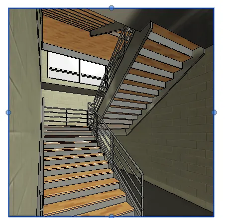
Click on Straight option and draw Stairs in the Staircase room
Adjust the stairs

created Stairs in the Staircase Room
Select ARCHITECTURE Tab
Go to Opening panel
Click on SHAFT
Go to PROPERTIES Browser
Change the Base Constraint
Change the Top constraint
Press Apply
Choose appropriate tool from the Draw panel and create Shaft opening
Opening is created for Stairs and Elevators.
Select INSERT tab
Go to Load From Library panel and click on Load Autodesk Family tool
Load Autodesk Family dialogue box opens
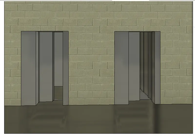
Choose M_Electric Lift-4 person wall based Type 1
Press Load
Select ARCHITECTURE tab.
Go to BUILD panel and click on Component tool and select Place a component option
Place the components in the Lift Lobby and Sevice Lobby
CURTAIN WALLS and GLASS PANELS: -
Select Architectural Tab
Go to BUILD panel and click on Wall tool
Go to Properties browser
Select Wall type: Curtain wall
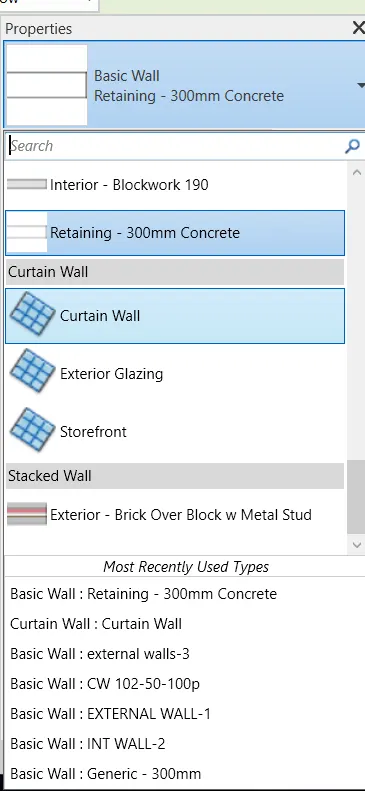
Draw at the centre of the Exterior walls
Go to Modify tab
Select Cut tool from Geometry panel
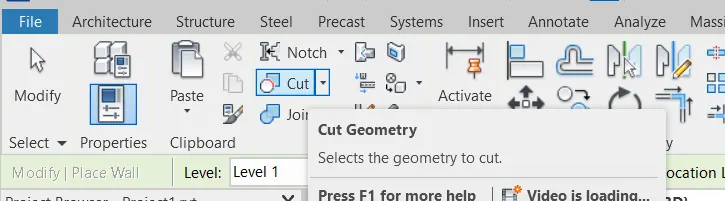
Select External wall first and then select Curtain wall.
Go to Properties browser
Set the Base Constraint: Level 1
Set the Top Constraint: Lower roof
Press Apply
Select Architectural Tab
Go to BUILD panel and click on Curtain Grid tool
Place the Grids on the Curtain wall.
Press Ok

Select Architectural Tab
Go to BUILD panel and click on MULLION tool
Select ALL GRID LINES option from the Placement panel

Go to Properties Browser
Choose Appropriate Mullions
Press Ok
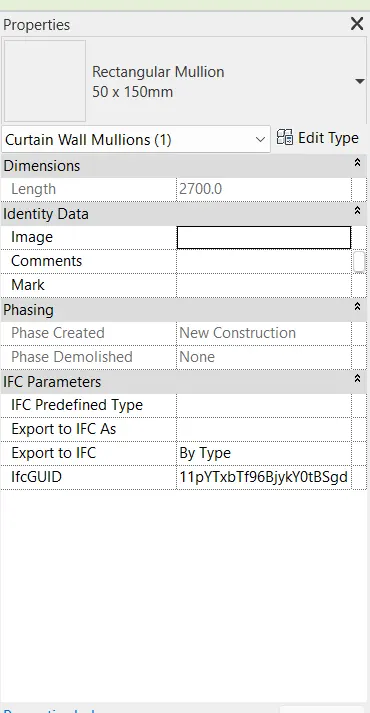
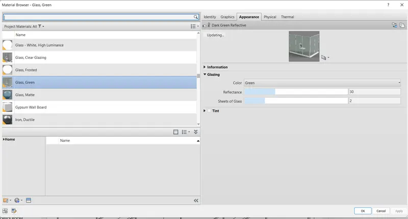
Select Curtain Wall in the Model Space
Go to Properties browser
Change the Material : Green Matte
Press Apply,
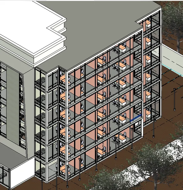
We created Curtain Grids
Created Mullions
Changed the Glass Material
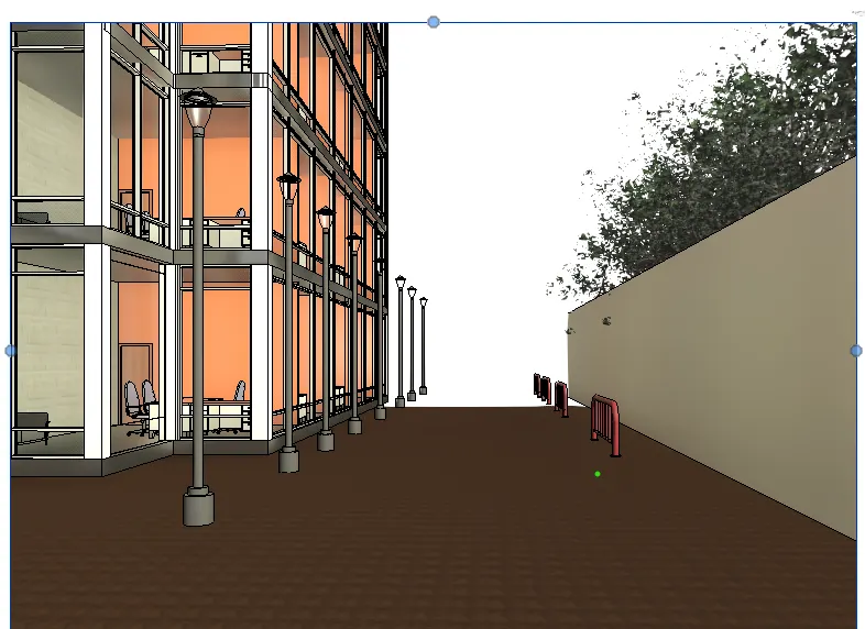
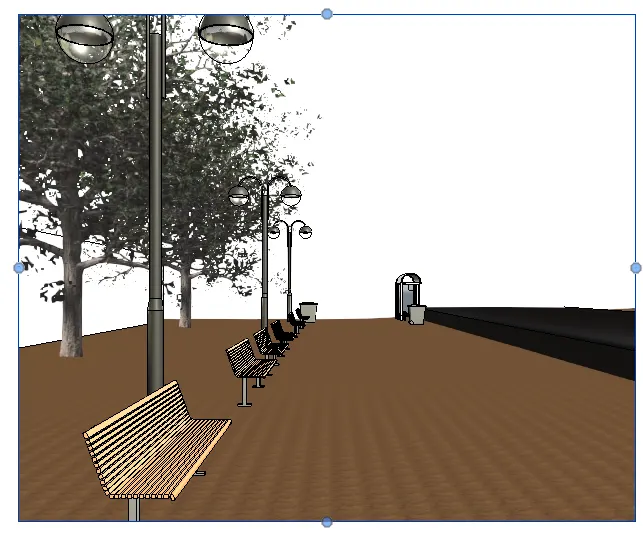
EXTERNAL LIGHTING: -
Go to Load From Library panel and click on Load Autodesk Family tool
Load Autodesk Family dialogue box opens
Choose Lighting Fixtures_LP_Dbl_5000mm_height
Choose Lighting Fixtures_pedestrain_Luminaries_250 watt
Press Load
Select ARCHITECTURE tab.
Go to BUILD panel and click on Component tool and select Place a component option
Place the components around the building.
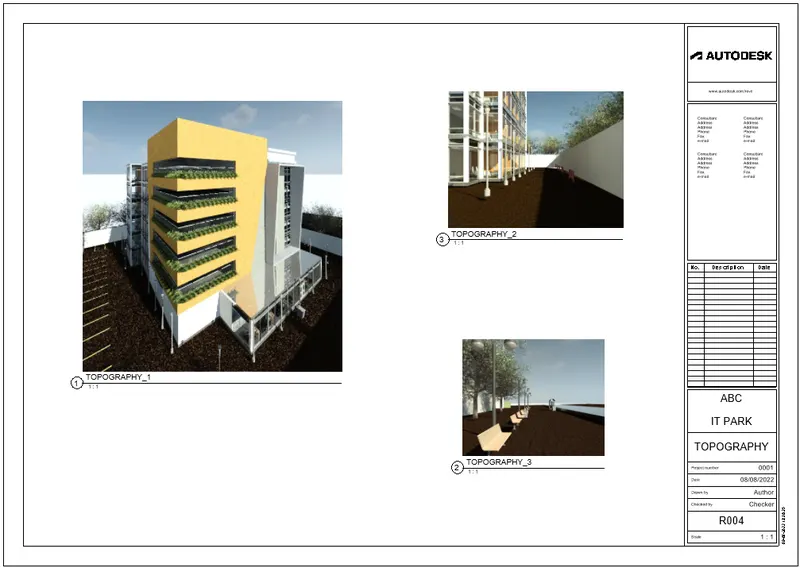
TOPOGRAPHIC COMPONENTS: -
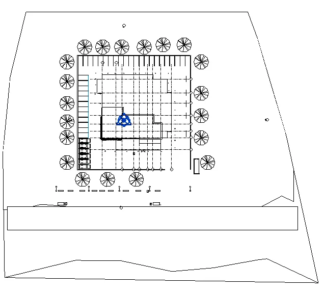
Select MASSING & SITE TAB
Choose Toposurface tool

In Project Browser
Go to Floor Plans
Click on Site
Mark Points on the model space
Change the Elevation at regular intervals
Surface is formed
Place the Surface at bottom of the Level 1
Go to Load From Library panel and click on Load Autodesk Family tool
Load Autodesk Family dialogue box opens
Select planting tab
Choose RPC Tree Deciduous Scarlet Oak 12.5 m
Choose RPC shrub Fountain grass
Press Load
Select ARCHITECTURE tab.
Go to BUILD panel and click on Component tool and select Place a component option
Place the components around the building.
place the shrubs at each level
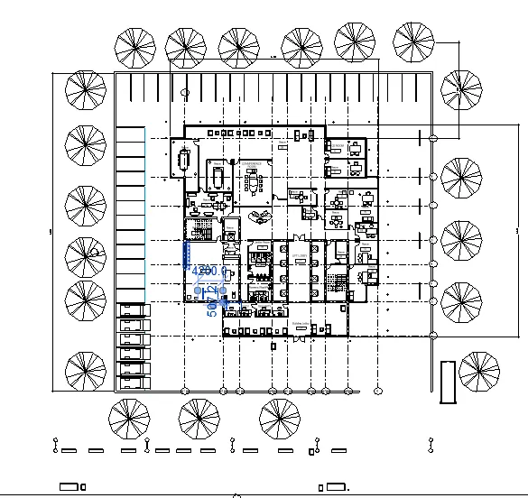
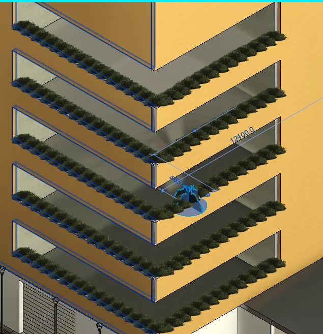
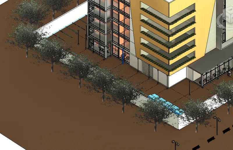
Go to Load From Library panel and click on Load Autodesk Family tool
Load Autodesk Family dialogue box opens
Select PARKING TAB
Choose M_parking space
Choose Site_Bike Stand
Press Load
Select ARCHITECTURE tab.
Go to BUILD panel and click on Component tool and select Place a component option
Place the components around the building.
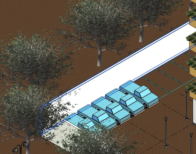
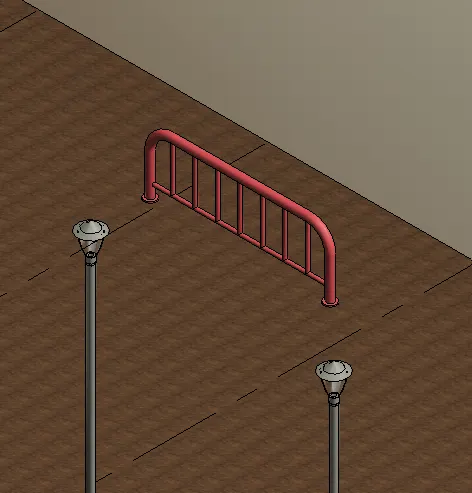
Go to Load From Library panel and click on Load Autodesk Family tool
Load Autodesk Family dialogue box opens
Select PARKING TAB
Choose SITE_PARK_BENCH
Choose SITE_BUS_STOP
Choose SITE_Domestic_wheely
Choose SITE_WASTE CONTAINER
Press Load
Select ARCHITECTURE tab.
Go to BUILD panel and click on Component tool and select Place a component option
Place the components at the appropriate position.
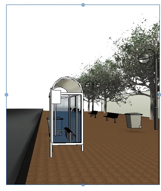
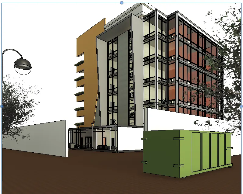
Select Architecture Tab
Go to Build Panel
Click on Component tool
Select Model in Place option
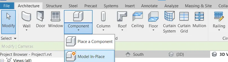
Family category and parameter dialogue box opens
Select Generic Model
Change name to Generic model 1
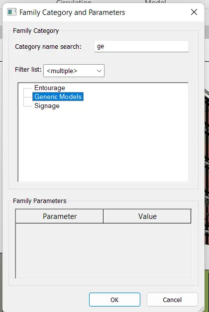
Select Extrusion tool
Set the Working plane

Select the Work plane
Choose the appropriate tool to draw the elevation in the South
In the Properties Browser, set the offset as 250units.
Press ok
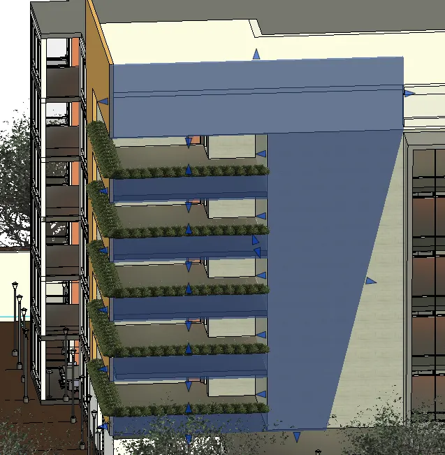
Select Architecture Tab
Go to Build Panel
Click on Component tool
Select Model in Place option
Family category and parameter dialogue box opens
Select Generic Model
Change name to Generic model 2
Select Extrusion tool
Set the Working plane
Select the Work plane
Choose the appropriate tool to draw the elevation in the West
In the Properties Browser, set the offset as 250units.
Press ok
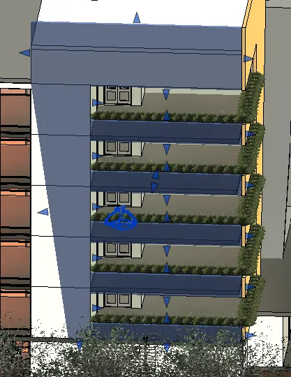
Select Architecture Tab
Go to Build Panel
Click on Component tool
Select Model in Place option
Family category and parameter dialogue box opens
Select Generic Model
Change name to Generic model 3
Select Extrusion tool
Set the Working plane
Select the Work plane
Choose the appropriate tool to draw the elevation in the South
In the Properties Browser, set the offset as 250units.
Press ok
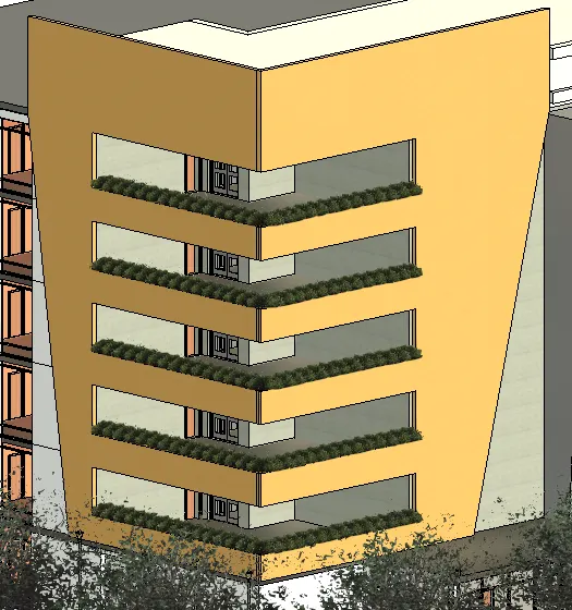
Select Void Forms and choose void extrusion from the dropdown list
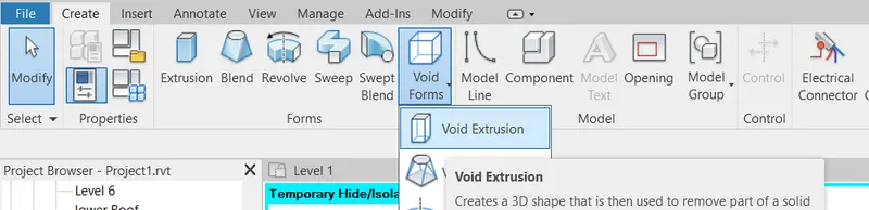
Set the Working plane
Select the Work plane

Choose the appropriate tool to draw the elevation in the South
Cut the component diagonally
Press OK
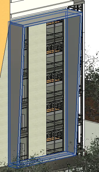
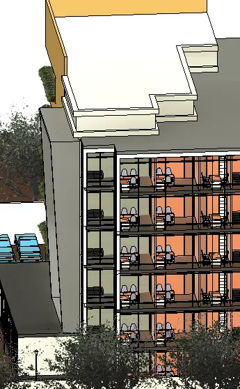
RESULT: -
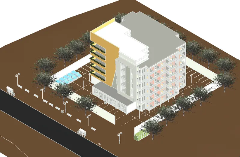
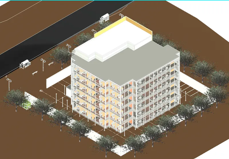
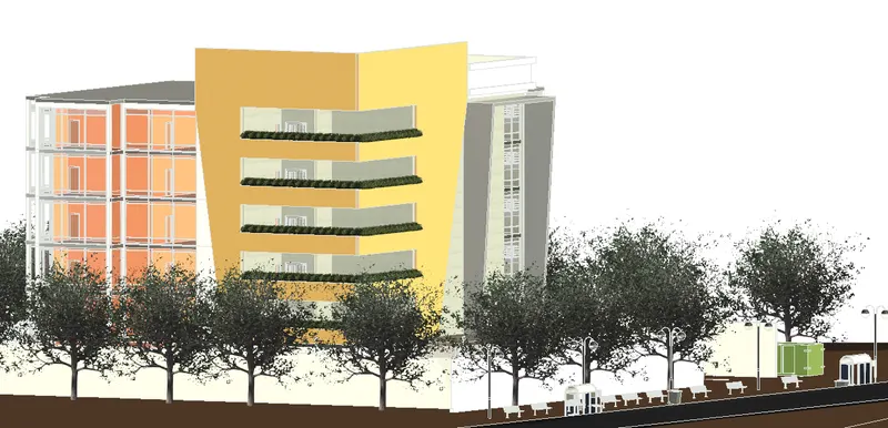
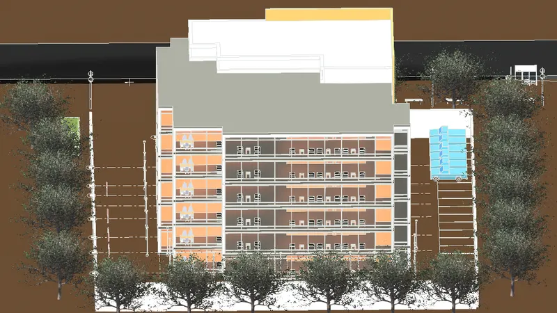
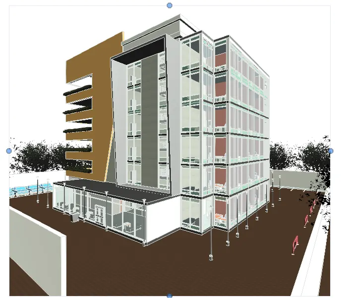
using the Architectural template, We created Grids and we created Levels for the office building.
We created Walls with approprite material
We created Floors
We created Ceilings and attached Lighting fixtures
We created rooms using Partition walls.
We added components to add details to each room.
We created Stairs and Elevators to provide accessibility
We created curtain walls and Glass panels to all the walls for the Aesthetic looks
we included interior and Exterior Lighting fixtures
We placed proper Topographic components from outside to add details to the model.
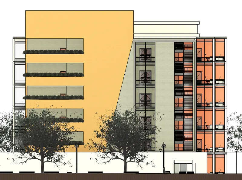
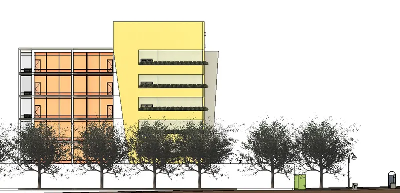
5Q)
AIM: -
Provide a set of drawings in an Architectural model and structural model using appropriate sheets to list the following details
- Floor plans with Annotations
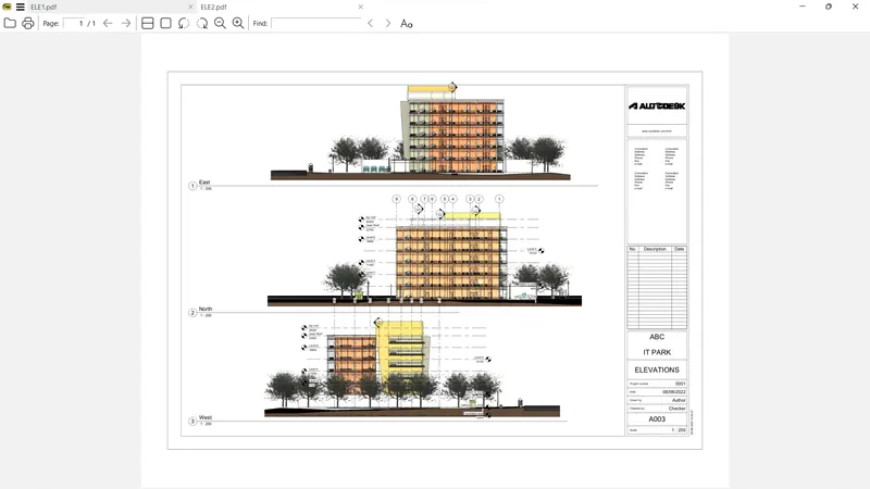
- Elevations
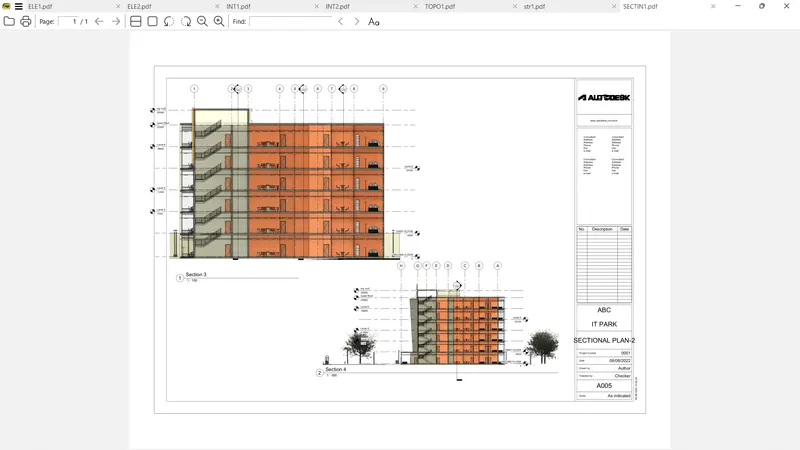
- Sections
PROCEDURE: -
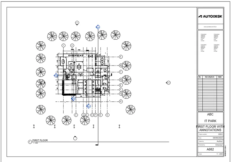
FLOOR PLANS
Select VIEW TAB
Go to Sheet Composition Panel and click on Sheet tool

New Sheet dialogue box opens
Select one Titleblock and press OK
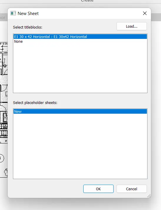
Sheet appears in the model space.
Select MANAGE TAB
Go to SETTINGS Panel and click on Project Information
Project Information dialogue box opens
Edit the data and press OK
Data changes in the sheet.
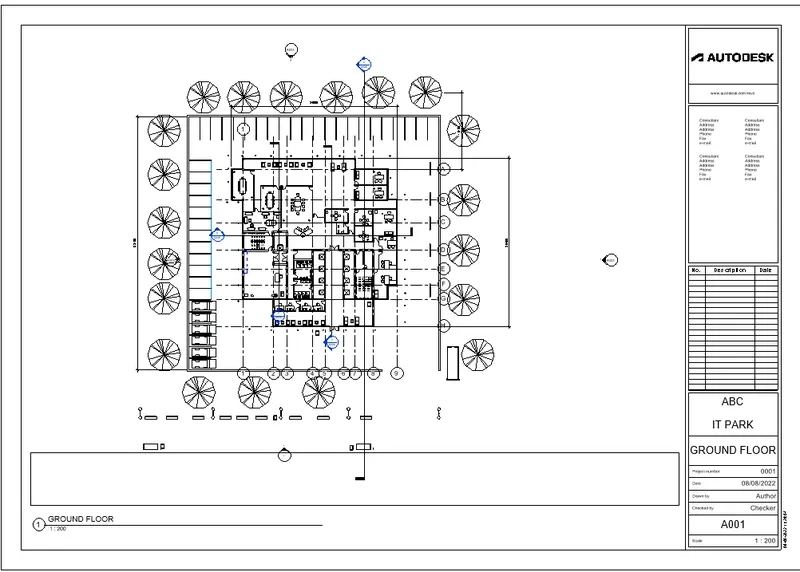
From the Project Browser, Go to Floor Plan column
Select Ground Floor plan and drag it to the sheet.
Adjust the plan in the sheet.
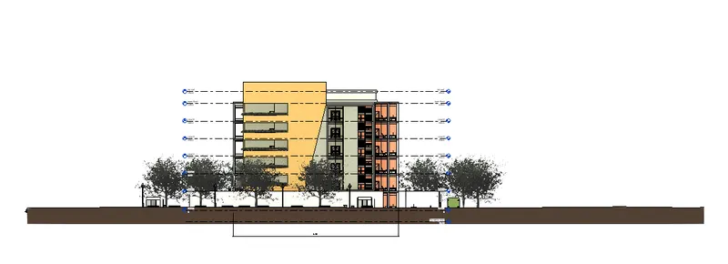
ELEVATIONAL PLANS
Select VIEW TAB
Go to Sheet Composition Panel and click on Sheet tool
New Sheet dialogue box opens
Select one Titleblock and press OK
Sheet appears in the model space.
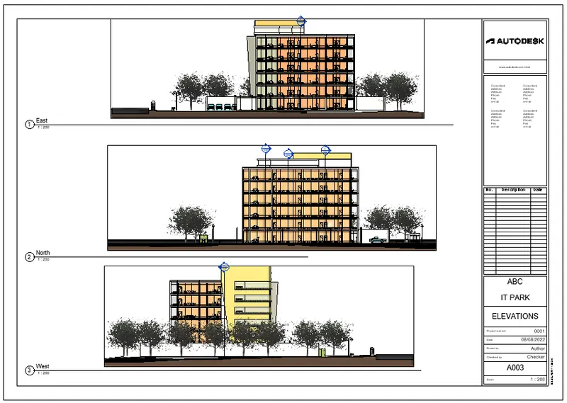
From the Project Browser, Go to ELEVATION Plan column
Select EAST, WEST, NORTH plans and drag it to the sheet.
Adjust the plan in the sheet.
SECTIONAL PANS
Select VIEW TAB
Go to Sheet Composition Panel and click on Sheet tool
New Sheet dialogue box opens
Select one Titleblock and press OK
Sheet appears in the model space.
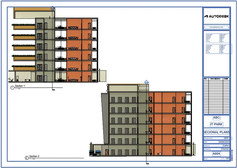
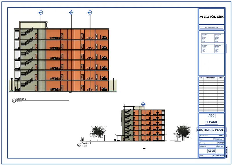
From the Project Browser, Go to SECTION Plan column
SelecT plans and drag it to the sheet.
Adjust the plan in the sheet.
FROM STRUCTURAL MODEL: -
ELEVATIONAL PLANS
Select VIEW TAB
Go to Sheet Composition Panel and click on Sheet tool
New Sheet dialogue box opens
Select one Titleblock and press OK
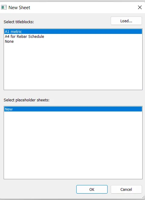
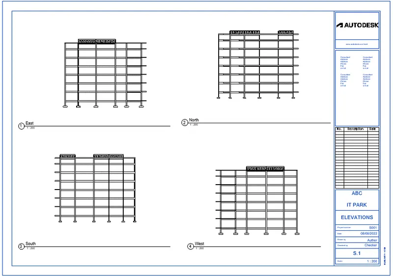
Sheet appears in the model space.
From the Project Browser, Go to ELEVATION Plan column
Select EAST, WEST, NORTH and SOUTH plans and drag it to the sheet.
Adjust the plan in the sheet.
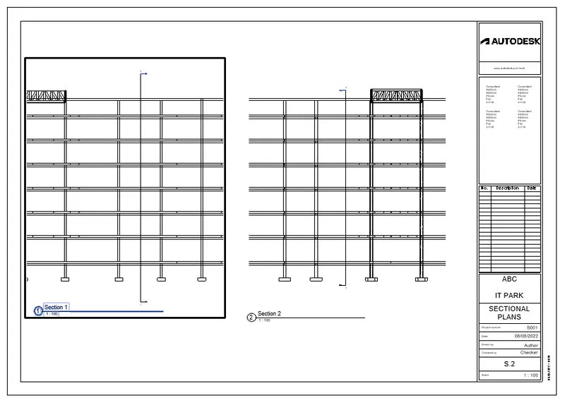
SECTIONAL PANS
Select VIEW TAB
Go to Sheet Composition Panel and click on Sheet tool
New Sheet dialogue box opens
Select one Titleblock and press OK
Sheet appears in the model space.
From the Project Browser, Go to SECTION Plan column
Select plans and drag it to the sheet.
Adjust the plan in the sheet.
RESULT: -
We created sheet templates.
We added plans to the sheet.
We created sheets for Architectural model and Structural model.
Provided a set of drawings in an Architectural model and structural model using following details
- Floor plans with Annotations
- Elevations
- Sections
6Q]
AIM: -
Render images of the 3D model produced
Attach Rendered images to the drawing sheet.
PROCEDURE: -
Select VIEW TAB
Go to Presentation panel
Click on Render

Rendering dialogue box opens
Quality
Settings: Medium
Output Settings
Resolution: screen
Lighting
Scheme: select appropriate option from the dropdown list
Background
Style: few Clouds
Click on Render
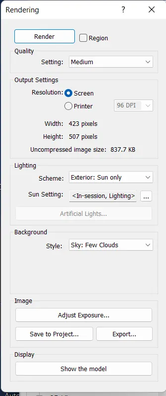
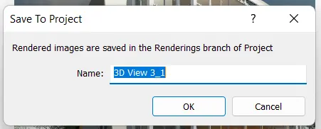
After Completion of Rendering Press Save to Project option
Save to Project dialogue box opens
Enter the Name and Press OK
Select VIEW TAB
Go to Sheet Composition Panel and click on Sheet tool
New Sheet dialogue box opens
Select one Titleblock and press OK
Sheet appears in the model space.
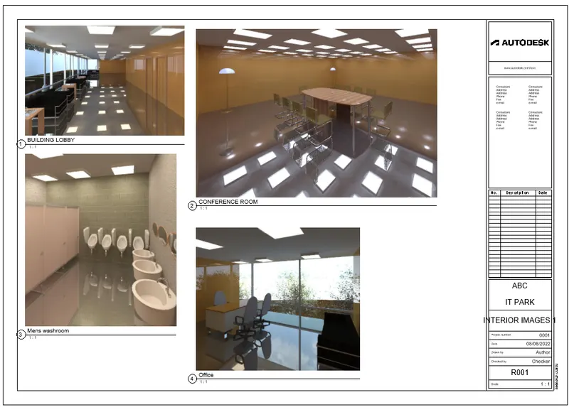
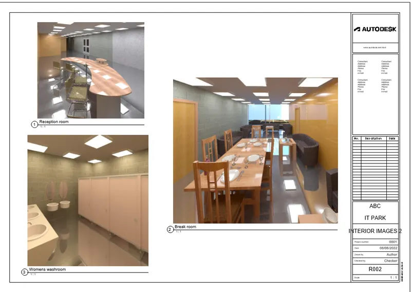
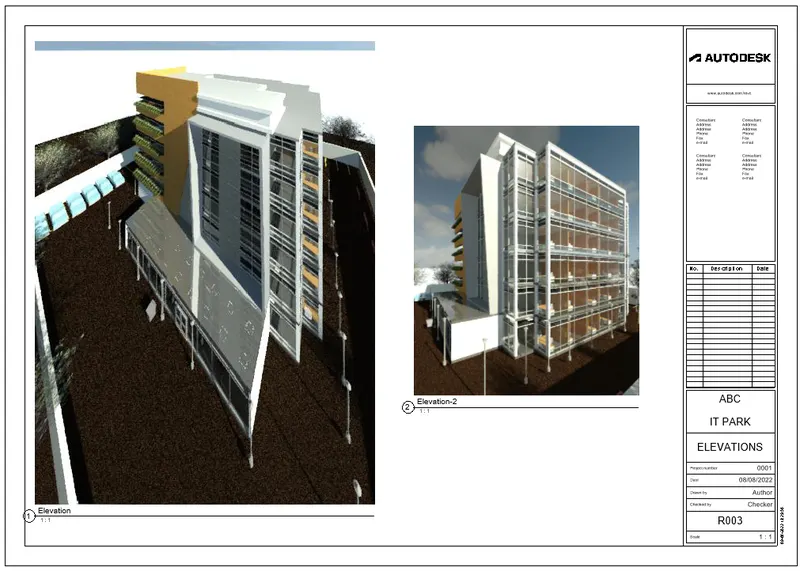
From the Project Browser, Go to Renderings column
Select images and drag it to the sheet.
Adjust the images in the sheet.
RESULT: -
We created Render images of the 3D model produced
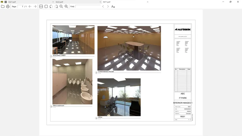
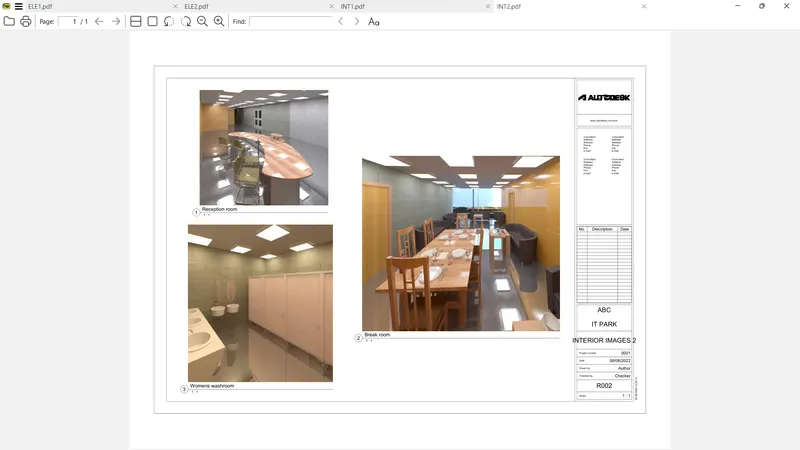
We rendered Interior rooms
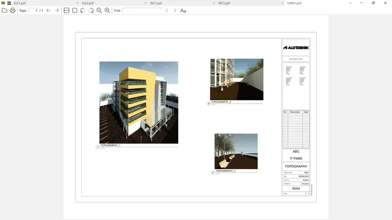
We rendered Topographic features of model
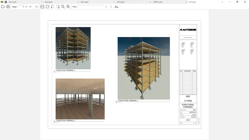
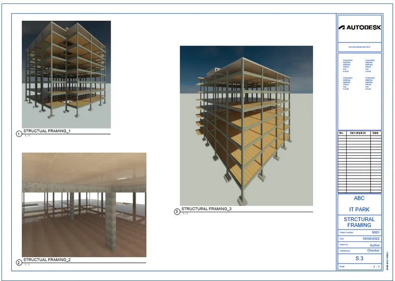
We rendered Structural framing
We attached Rendered images to the drawing sheet.
7Q]
AIM: -
Print the set of drawing sheets created
Submit the drawings.
PROCEDURE: -
Open the required sheet to print
Press CTRL + P on the keyboard
Print Setup dialogue box opens
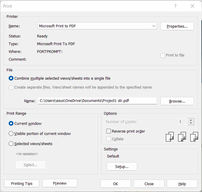
Set the Print Name
File type
Print Range
Options
Click on Setup settings option for page setup
Print Setup dialogue box opens
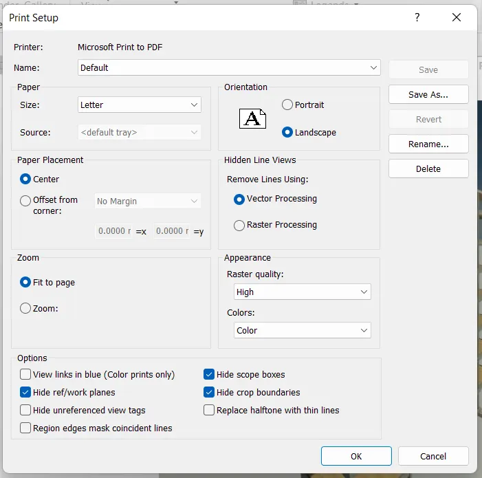
Set the Paper size
Orientation
Paper placement
Zoom settings
Appearance Settings
Press OK
Save the file at the required destination
RESULT: -
We saved the set of Drawings Sheets to Pdf Format
Elevation Sheet
Sectional Plan Sheet
Interior Details Sheet
Topography Sheet
Structural Framing Sheet
submitted the Drawings from the Architecture and Structure model.