Creating Architectural and Structural model with 3D rendering using REVIT
Creating Architectural and Structural model with 3D rendering using REVIT
1) Select the type of structure you want to build from one of the three below:
a. Multi-Unit Residential Apartment
b. Office Buildings
c. School
AIM:
To create layout, walls, floors, ceilings, roof, place some components in each rooms, doors and windows in appropriate places, provide annotations, create sheets, sectional views, 3D views, Elevations and plan views. Also, explain the procedure step by step and obtain the result.
INTRODUCTION:
Revit is a BIM (Building Information Modelling) software to drive efficiency and accuracy across the project lifecycle, from conceptual design, visualisation and analysis to fabrication and construction.
Begin modelling in 3D with accuracy and precision.
Automatically update floor plans, elevations and sections as your model develops.
PROCEDURE:
- Open the Revit Software
- Create a new project
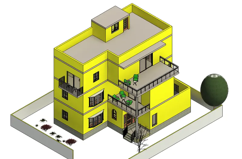
- Here, I have decided to design and develop a "Multi-Unit Residential Building".
- Open East elevation, go to architecture tab and select Levels to create Multi Levels.
- Here, I have created 7 Levels for the developing the building.
- Then, Open the level 0, plan and draw the ground floor walls and rooms.
- Now, go to architectural tab select Grids and mark the grids for column placements.
- After completing this, start developing the house as per requirements.
- The detailed procedures and components used are explained in the upcoming answers.
RESULT:
The detailed procedures and components used, Architectural plan, Structural Plan, Elevations, Sections and 3D views are explained/showcased in the upcoming answers.
2) Assume reasonable assumptions for geographic and location details for your project modeling. Based on assumptions and type of structure selected identify the modeling requirements from NBC.
AIM:
To create layout, walls, floors, ceilings, roof, place some components in each rooms, doors and windows in appropriate places, provide annotations, create sheets, sectional views, 3D views, Elevations and plan views. Also, explain the procedure step by step and obtain the result.
INTRODUCTION:
Revit is a BIM (Building Information Modelling) software to drive efficiency and accuracy across the project lifecycle, from conceptual design, visualisation and analysis to fabrication and construction.
Begin modelling in 3D with accuracy and precision.
Automatically update floor plans, elevations and sections as your model develops.
PROCEDURE:
- Open the Revit Software
- Create a new project
- Here, I have decided to design and develop a "Multi-Unit Residential Building".
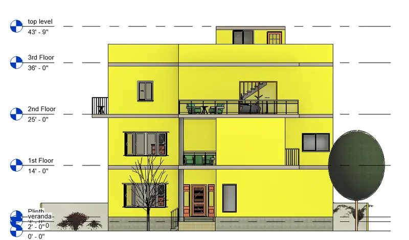
- It is Located in 'Dharmapuri'.
- The plot comes under the panchayat division.
NBC Guidelines.
- Front offset 1.5 m for street width less than 7.5m.
- For buildings of height above 10m, minimun rear and side open spaces are required to increase with the height of a rule of 1m for every 5m height.
- The plot size is 12.19x15.24m. total area is 185 sq.m. Individual Floor area is 140 sq.m.
- The width of the road is 4.5m (15').
RESULT:
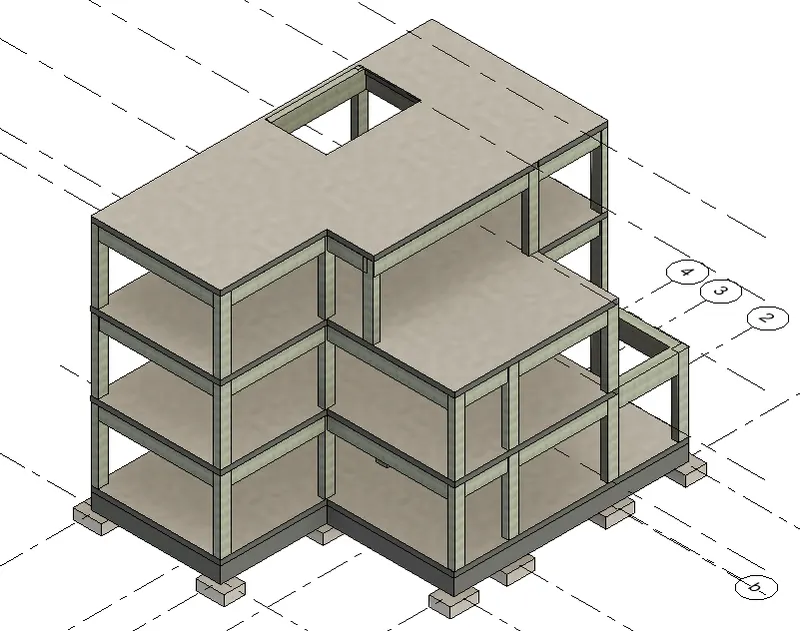
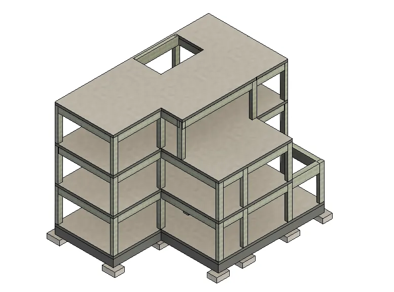
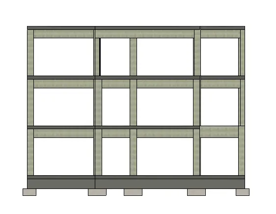
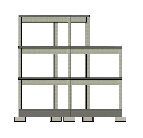
3) Using the structural model, include the following components based on the type of structure selected
a. Foundation – Isolated / Wall/Matt Foundation
b. Columns
c. Beams Connected to Columns
d. Roof Framing/ Truss
e. Floor / Decks
f. Floor Openings for Elevators and Stairs
AIM:
To create structural components like foundation, columns, beams, roof, floor, floor opening for stairs in a structural model. Also, explain the procedure step by step and obtain the result.
INTRODUCTION:
Revit is a BIM (Building Information Modelling) software to drive efficiency and accuracy across the project lifecycle, from conceptual design, visualisation and analysis to fabrication and construction.
Begin modelling in 3D with accuracy and precision.
Automatically update floor plans, elevations and sections as your model develops.
PROCEDURE:
- Open the Revit Software
- Create a new project, select structural template.
- Here, I have decided to design and develop a "Multi-Unit Residential Building".
- Open East elevation, go to structural tab and select Levels to create Multi Levels.
- Here, I have created 7 Levels for the developing the building.
- Then, Open the level 0, plan and draw the grids for column position.
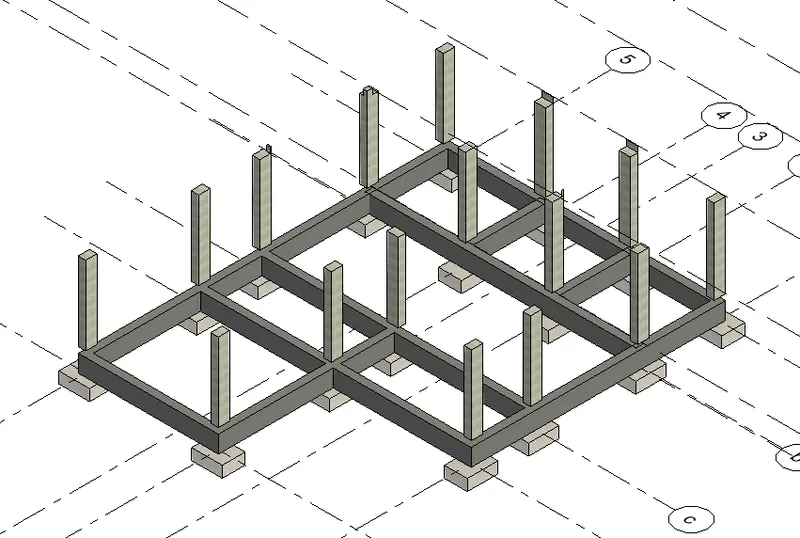
- Now, place the footing and column at required places.
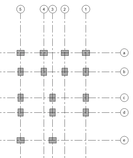
- After, placing the footing insert columns and connect the levels.
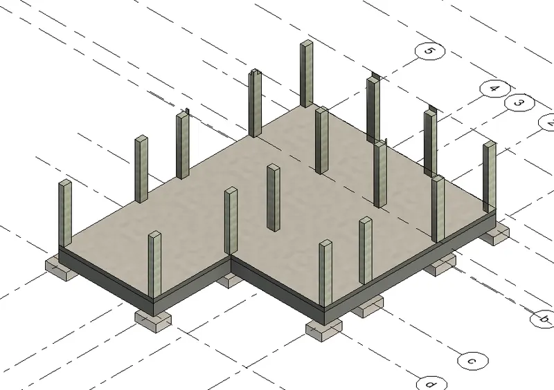
- Using Beams create grade beams, connect all the columns and again create beams to support the slab.
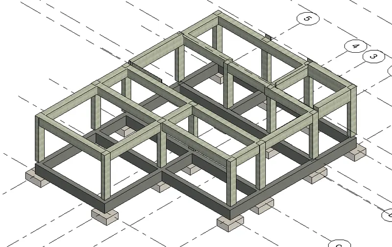
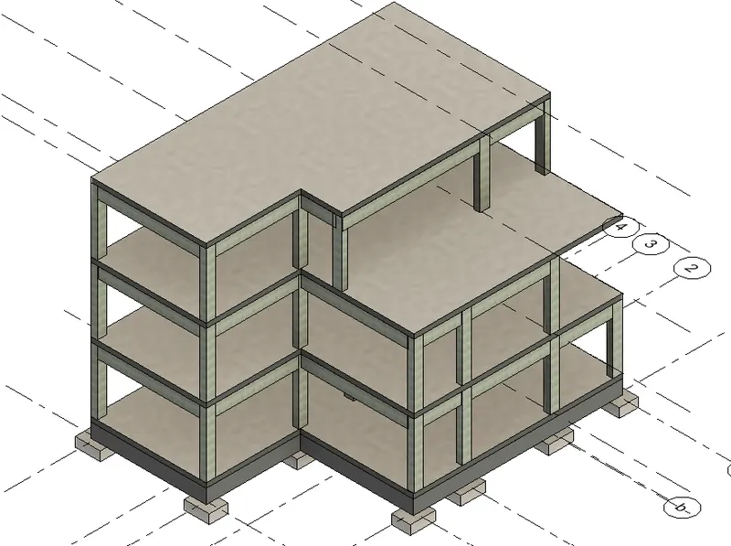
- Using Floor option, i have created concrete floors and slabs.
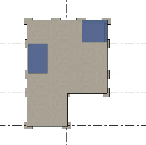
- Now, to provide open space for stairs/elevators, go to structural tab choose shaft opening and select the area in the slab to be open and mention level/height upto which the opening needs to be provided.
RESULT:
4) Using the architectural model, include the following components based on the type of structure selected
a. Wall Layout with appropriate material and finishing
b. Exterior façade with fancy finish
c. Interior partition walls to size rooms
d. Components to add details to a room ( Desk, Chair, Lighting, Plumbing fixtures)
e. Add components such as stairs Elevators
f. Have at-least one side of the building with curtain walls and glass panels
g. Include interior and exterior lighting fixtures
h. Place proper topographic components from outside ( Trees, Parking, Plants) to add details to the model
AIM:
To create layout, walls, floors, ceilings, roof, place some components in each rooms, doors and windows in appropriate places, provide annotations, create sheets, sectional views, 3D views, Elevations and plan views. Also, explain the procedure step by step and obtain the result.
INTRODUCTION:
Revit is a BIM (Building Information Modelling) software to drive efficiency and accuracy across the project lifecycle, from conceptual design, visualisation and analysis to fabrication and construction.
Begin modelling in 3D with accuracy and precision.
Automatically update floor plans, elevations and sections as your model develops.
PROCEDURE:
- Open the Revit Software
- Create a new project, open architectural template.
- Here, I have decided to design and develop a "Multi-Unit Residential Building".
- Open East elevation, go to architecture tab and select Levels to create Multi Levels.
- Here, I have created 7 Levels for the developing the building.
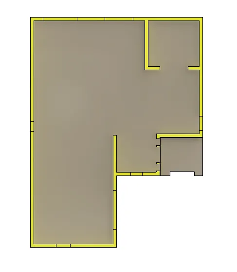
- Then, Open the plinth level, plan and draw the ground floor walls and rooms.
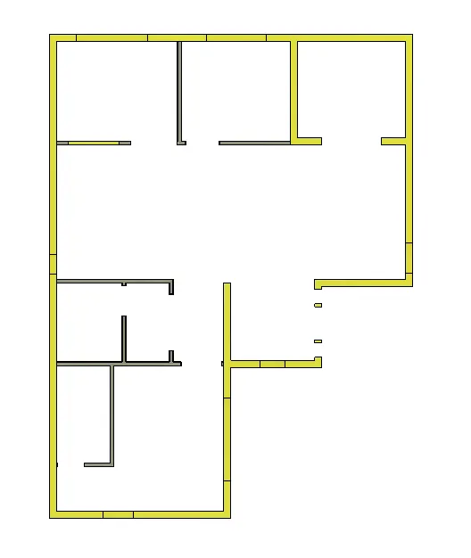
- Again using the walls options, i have inserted interior walls to create rooms.
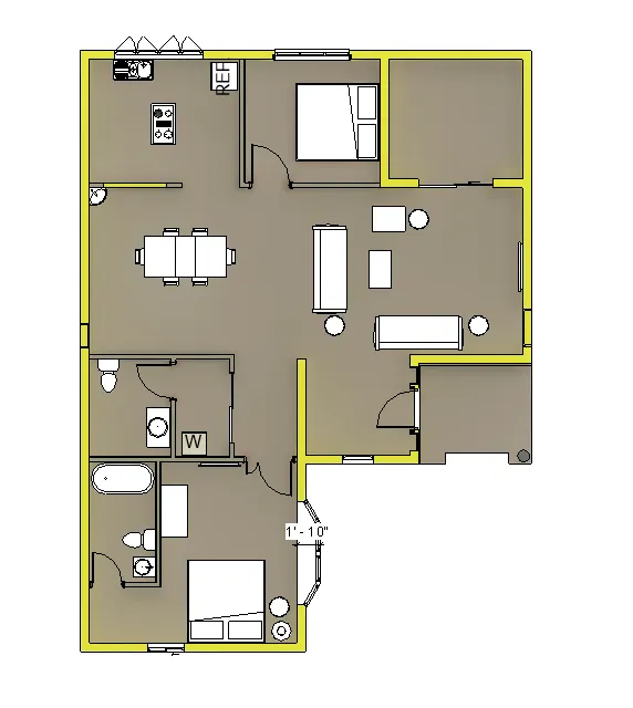
- Then using components and load family options, i have inserted various components like furnitures, doors, windows, kitchen equipments, plumbing fixtures.
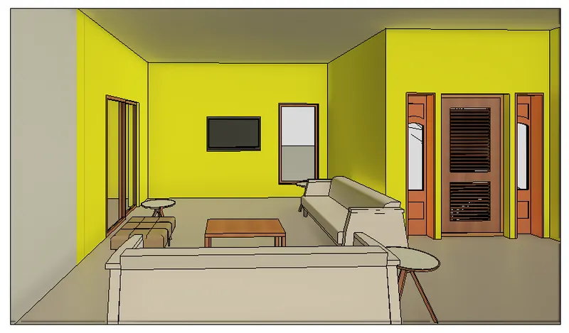
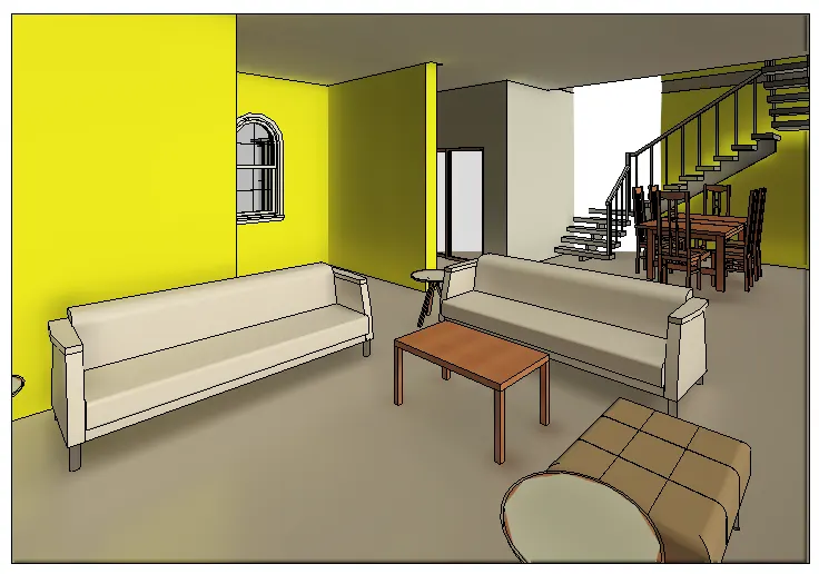
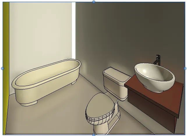
- Using Stairs options, i have created and customised stairs using edit type for this building.
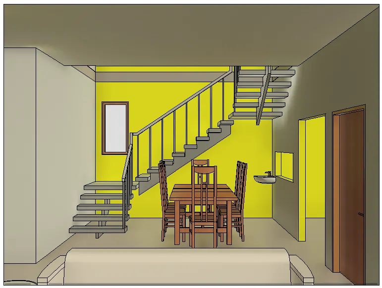
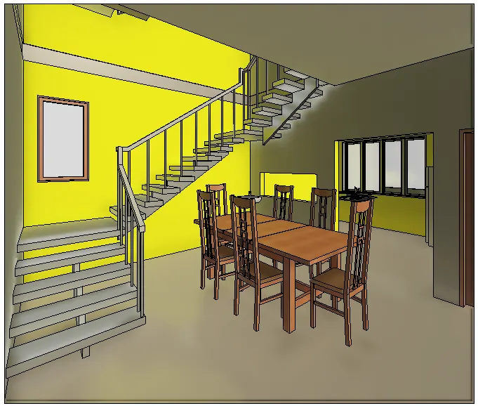
- I have inserted large Glass panel doors for the balcony.
- I have created ceiling beneath the slab and inserted lightings using components and load family option.
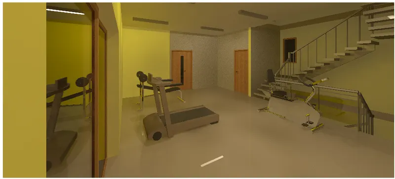
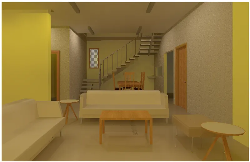
- Finally, select the massing & site tab, choose site component and place the desired trees, plants.
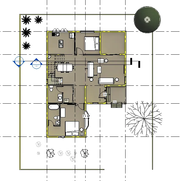
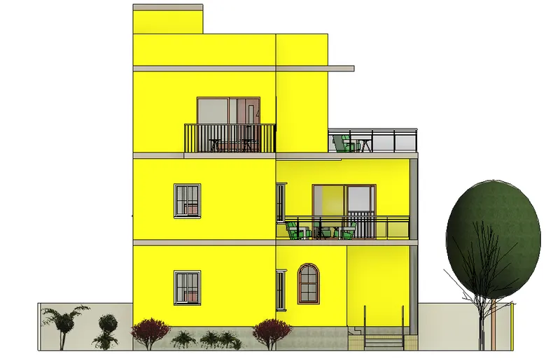
RESULT:
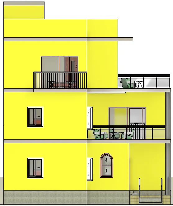
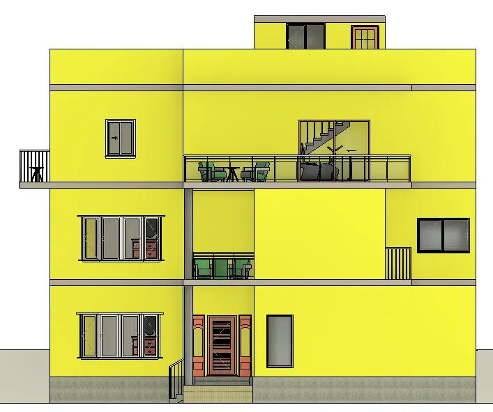
The following images shows the fully completed house with all the components.
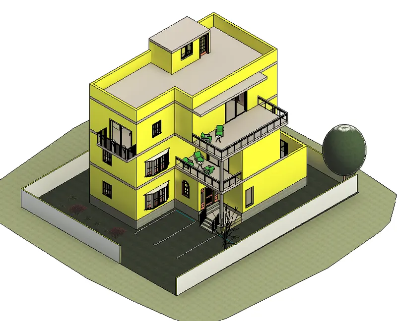
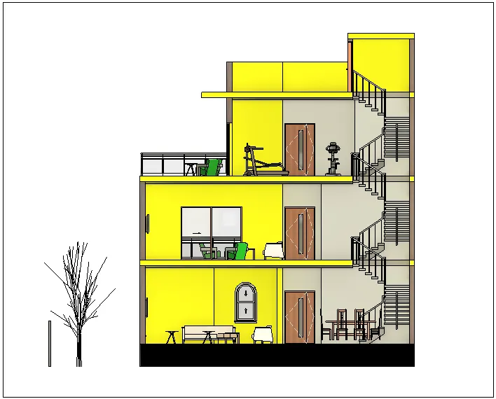
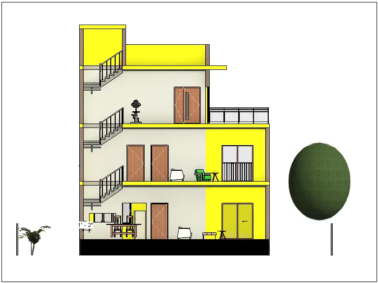
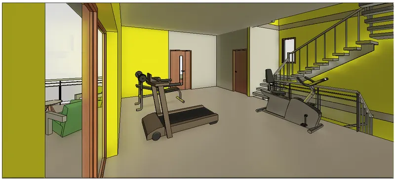
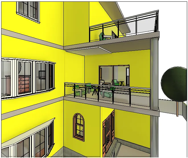
5) Provide a set of drawings in an architectural and structural model to list the following details with categories and appropriate sheet templates included
a. Floor Plans with Annotations
b. Elevations
c. Sections
AIM:
To create layout, walls, floors, ceilings, roof, place some components in each rooms, doors and windows in appropriate places, provide annotations, create sheets, sectional views, 3D views, Elevations and plan views. Also, explain the procedure step by step and obtain the result.
INTRODUCTION:
Revit is a BIM (Building Information Modelling) software to drive efficiency and accuracy across the project lifecycle, from conceptual design, visualisation and analysis to fabrication and construction.
Begin modelling in 3D with accuracy and precision.
Automatically update floor plans, elevations and sections as your model develops.
PROCEDURE:
- Open the Revit Software.
- To create Sheets,
- Go to the View tab and select Sheet option.
- A tab will open and select the type of sheet which is wanted.
- The selected sheet will appear on the screen as shown below.
- Go to the View tab and select Sheet option.
- A tab will open and select the type of sheet which is wanted.
- In order to insert any view in the sheet, Simply Drag the file from the projects browser and place it in the sheet and adjust the scale accordingly.
- The following image shows the Floor plans with annotations.
- Ground Floor plan in the sheet.
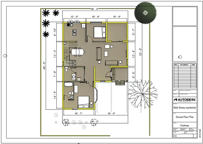
- Go to the View tab and select Sheet option.
- A tab will open and select the type of sheet which is wanted.
- In order to insert any view in the sheet, Simply Drag the file from the projects browser and place it in the sheet and adjust the scale accordingly.
- First Floor plan in the sheet.
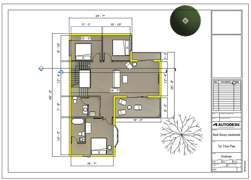
- Go to the View tab and select Sheet option.
- A tab will open and select the type of sheet which is wanted.
- In order to insert any view in the sheet, Simply Drag the file from the projects browser and place it in the sheet and adjust the scale accordingly.
- 2nd Floor plan in the sheet.
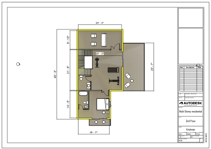
- Go to the View tab and select Sheet option.
- A tab will open and select the type of sheet which is wanted.
- In order to insert any view in the sheet, Simply Drag the file from the projects browser and place it in the sheet and adjust the scale accordingly.
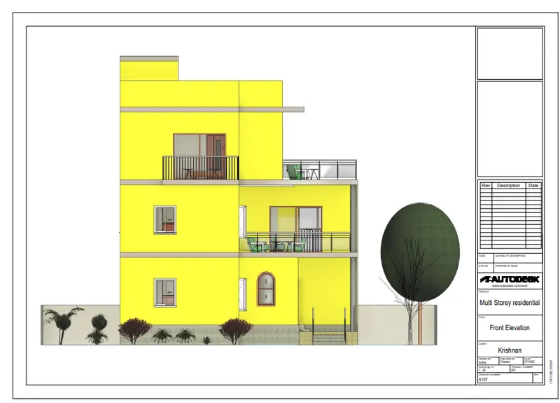
- Front elevation in the sheet.
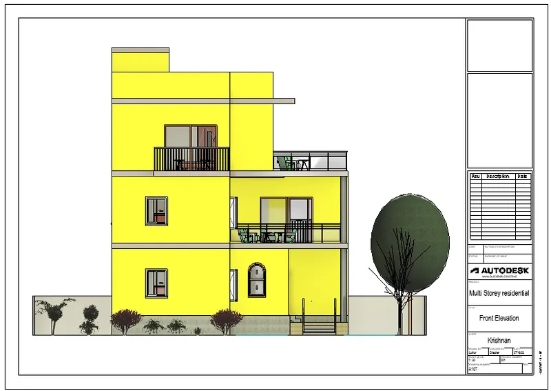
- Go to the View tab and select Sheet option.
- A tab will open and select the type of sheet which is wanted.
- In order to insert any view in the sheet, Simply Drag the file from the projects browser and place it in the sheet and adjust the scale accordingly.
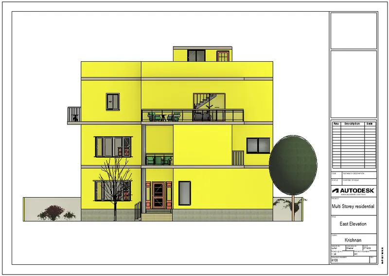
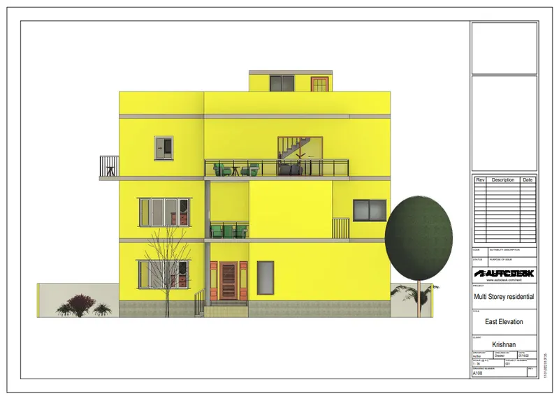
- East elevation in the sheet.
- Go to the View tab and select Sheet option.
- A tab will open and select the type of sheet which is wanted.
- In order to insert any view in the sheet, Simply Drag the file from the projects browser and place it in the sheet and adjust the scale accordingly.
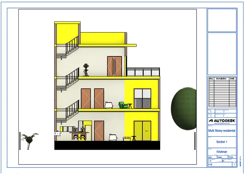
- Section 1 in the sheet.
- Go to the View tab and select Sheet option.
- A tab will open and select the type of sheet which is wanted.
- In order to insert any view in the sheet, Simply Drag the file from the projects browser and place it in the sheet and adjust the scale accordingly.
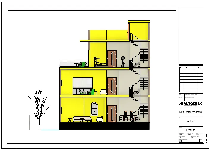
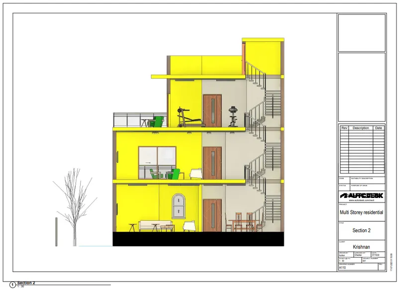
- Section 2 in the sheet.
- Go to the View tab and select Sheet option.
- A tab will open and select the type of sheet which is wanted.
- In order to insert any view in the sheet, Simply Drag the file from the projects browser and place it in the sheet and adjust the scale accordingly.
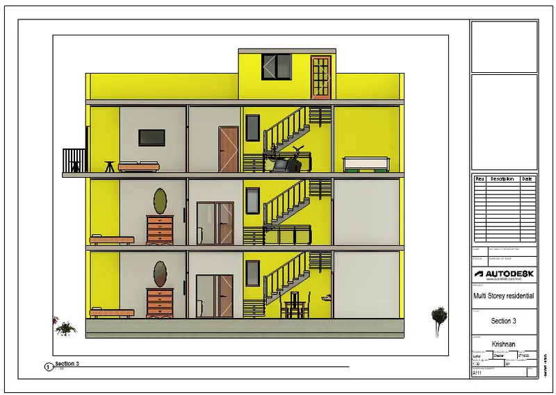
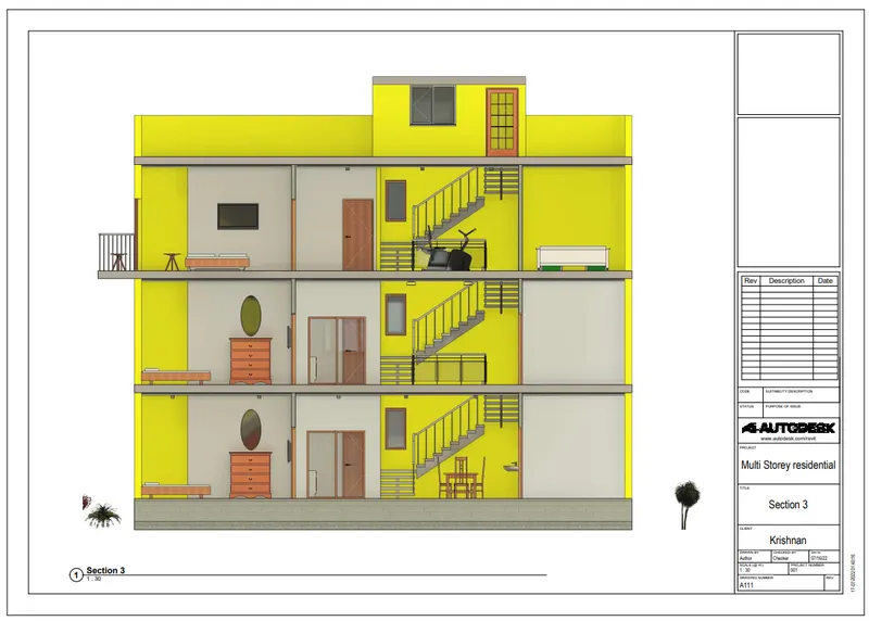
- Section 3 in the sheet.
- Go to the View tab and select Sheet option.
- A tab will open and select the type of sheet which is wanted.
- In order to insert any view in the sheet, Simply Drag the file from the projects browser and place it in the sheet and adjust the scale accordingly.
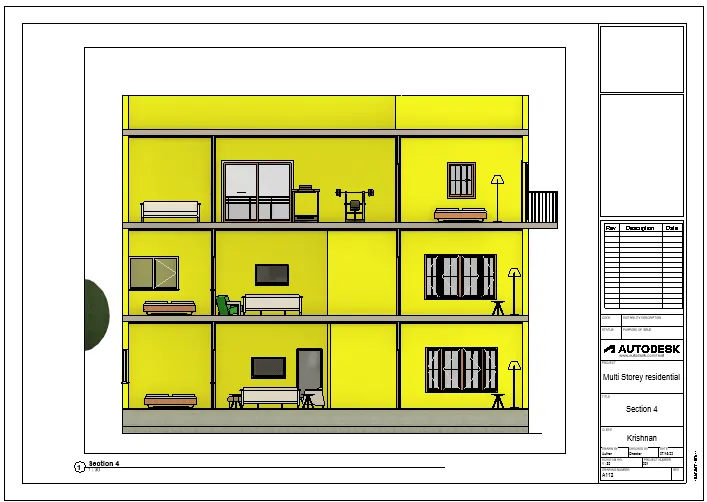
- Section 4 in the sheet.
RESULT:
6) Using the Rendering settings, Render images of the 3D model produced and include the rendered images to the drawing sheets
a. Rendering from interior rooms
b. Rendering from out showing topographic features
c. Rendering through structural framing
AIM:
To create rendered images of interior rooms, topography features, structural framing and insert it in the sheets.
INTRODUCTION:
Revit is a BIM (Building Information Modelling) software to drive efficiency and accuracy across the project lifecycle, from conceptual design, visualisation and analysis to fabrication and construction.
Begin modelling in 3D with accuracy and precision.
Automatically update floor plans, elevations and sections as your model develops.
PROCEDURE:
- Open the Revit Software.
- To create Sheets,
- Go to the View tab and select Sheet option.
- A tab will open and select the type of sheet which is wanted.
- The selected sheet will appear on the screen as shown below.
- Now, to render images, go to view tab, select render and adjust the settings like sun exposure, artificial lights and region.
- After rendering is done, save the rendered image to the project.
- After saving, drag the rendered image to include in the sheet and name the sheet.
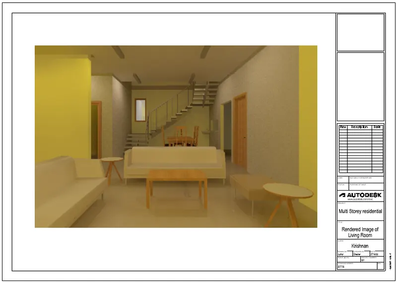
- Rendered Interior living room.
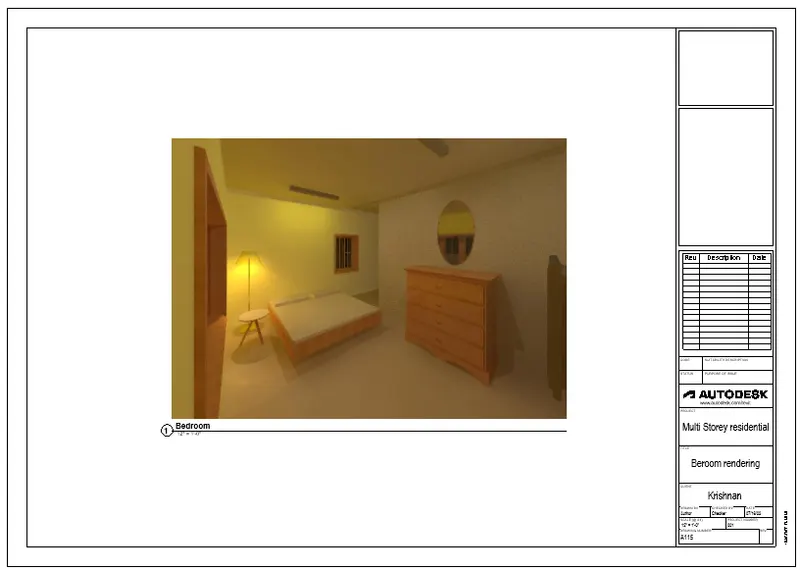
- Rendered Interior bedroom with artificial lights included in the sheet.
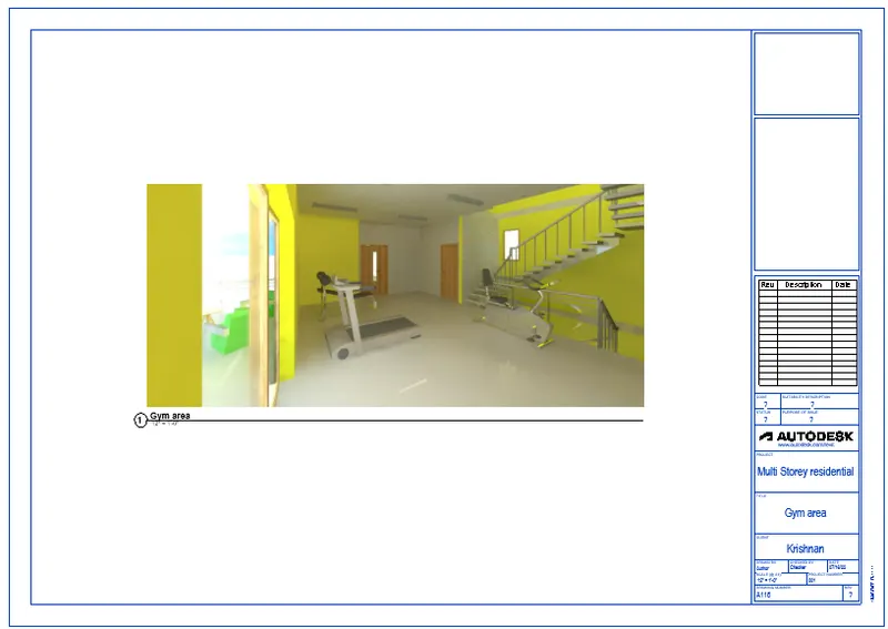
- Rendered Gym area with artificial lights and sun exposure included in the sheet.
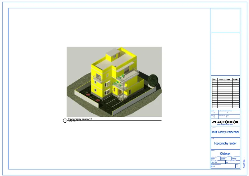
- To render images, go to view tab, select render and adjust the settings like sun exposure, artificial lights and region.
- After rendering is done, save the rendered image to the project.
- After saving, drag the rendered image to include in the sheet and name the sheet.
- Rendered topographic view included in the sheet.
- To render images, go to view tab, select render and adjust the settings like sun exposure, artificial lights and region.
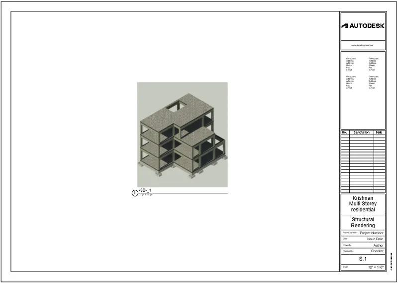
- After rendering is done, save the rendered image to the project.
- After saving, drag the rendered image to include in the sheet and name the sheet.
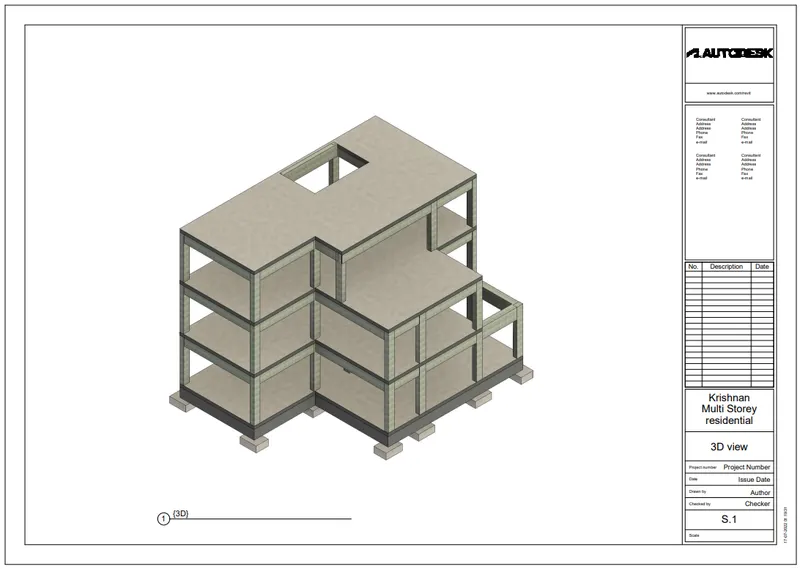
- Rendered Structural framing included in the sheet.
RESULT:
Rendered images in the sheets.
7) Print the set of drawing sheets created and submit the drawings from the architecture and structure model
AIM:
To print the set of drawing sheets created from the architectural and structural model.
INTRODUCTION:
Revit is a BIM (Building Information Modelling) software to drive efficiency and accuracy across the project lifecycle, from conceptual design, visualisation and analysis to fabrication and construction.
Begin modelling in 3D with accuracy and precision.
Automatically update floor plans, elevations and sections as your model develops.
PROCEDURE:
- Open the Revit Software.
- To create Sheets,
- Go to the View tab and select Sheet option.
- A tab will open and select the type of sheet which is wanted.
- The selected sheet will appear on the screen as shown below.
- In order to insert any view in the sheet, Simply Drag the file from the projects browser and place it in the sheet and adjust the scale accordingly.
- To print the sheet, use Ctrl+P command, a dialogue box will open , in that choose the option which ever is required either print or save as pdf, here I chose to save as pdf and give the name to file and save it.
- The pdf will be saved in the destination.
- Open the Pdf.
- In order to insert any view in the sheet, Simply Drag the file from the projects browser and place it in the sheet and adjust the scale accordingly.
- To print the sheet, use Ctrl+P command, a dialogue box will open , in that choose the option which ever is required either print or save as pdf, here I chose to save as pdf and give the name to file and save it.
- The pdf will be saved in the destination.
- Open the Pdf.
- In order to insert any view in the sheet, Simply Drag the file from the projects browser and place it in the sheet and adjust the scale accordingly.
- To print the sheet, use Ctrl+P command, a dialogue box will open , in that choose the option which ever is required either print or save as pdf, here I chose to save as pdf and give the name to file and save it.
- The pdf will be saved in the destination.
- Open the Pdf.
- In order to insert any view in the sheet, Simply Drag the file from the projects browser and place it in the sheet and adjust the scale accordingly.
- To print the sheet, use Ctrl+P command, a dialogue box will open , in that choose the option which ever is required either print or save as pdf, here I chose to save as pdf and give the name to file and save it.
- The pdf will be saved in the destination.
- Open the Pdf.
- In order to insert any view in the sheet, Simply Drag the file from the projects browser and place it in the sheet and adjust the scale accordingly.
- To print the sheet, use Ctrl+P command, a dialogue box will open , in that choose the option which ever is required either print or save as pdf, here I chose to save as pdf and give the name to file and save it.
- The pdf will be saved in the destination.
- Open the Pdf.
RESULT:
- To print the sheet, use Ctrl+P command, a dialogue box will open , in that choose the option which ever is required either print or save as pdf, here I chose to save as pdf and give the name to file and save it.
- The pdf will be saved in the destination.
- Open the Pdf.
The following images shows the drawing sheets saved as PDF files.