Creating Architectural and Structural model with 3D rendering using REVIT
PROJECT 2
AIM
To create Architectural and Structural model with 3D rendering using REVIT
INTRODUCTION
1. The type of structure to build is Office Building
2. Geographic and location details - Modeling requirements from NBC
- Geographic and location details: Thiruvananthapuram, Kerala, India (Flat surface topograpgy)
- The modeling requirements from NBC based on assumptions are:
- The open space around the building shall not be less than 4.5m.
- The type of construction is taken as type 2 construction, the Floor Area Ratio (FAR) value for the business building shall be taken as 2.9.
- The plot size is taken as 45mx45m i.e, 2025m2 and individual floor area is 1080m2. Hence, FAR value obtained is 2.66, which is within the prescribed limits as per NBC.
- The width of the road abutting the building is taken as 9m.
PROCEDURE
STEP 1: Collaborate and synchronize Architectural and Structural Model
- Open Revit software and click 'New'
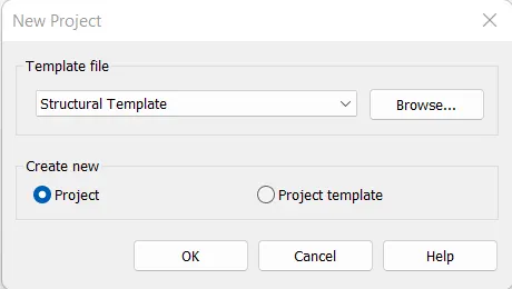
- Select 'Structural Template' as the template file on 'New Project' and click 'OK'
- Click 'Location' in the 'Manage' tab
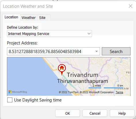
- Enter the project coordinates in the 'Project Address' and click 'OK'
- Click 'Grids' in the 'Architecture' tab
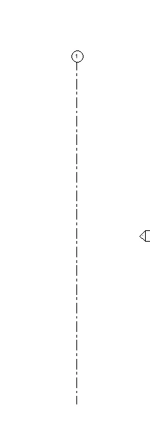
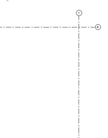
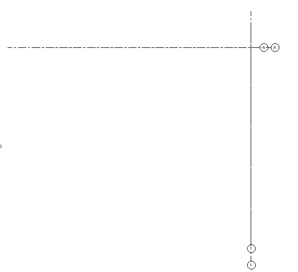
- Draw a longitudinal grid 1
- Draw a transverse grids A
- Click 'Coordinates' in the 'Manage' tab
- Click 'Specify Coordinates at Point' under 'Coordinates'
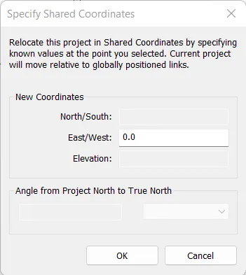
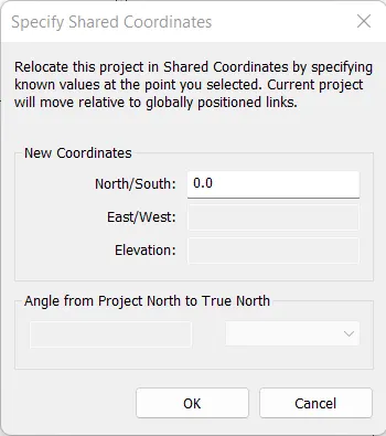
- Click on the grids and set 'East/West: 0.0' and 'North/South: 0.0' in 'New Coordinates' under 'Specify Shared Coordinates'
- Type 'VG' to open Visibility/Graphics
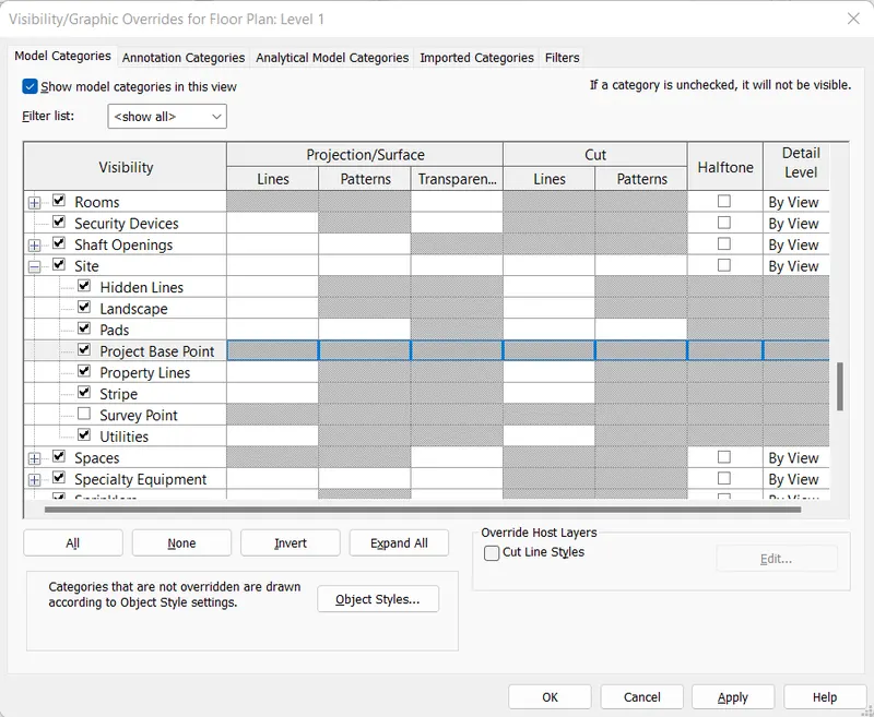
- Enable 'Project Base Point' under 'Site', click 'Apply' and then 'OK'
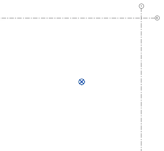
- Click the 'Project Base Point', move it and place it in the new cordinates (N/S: 0.0, E/W: 0.0) created
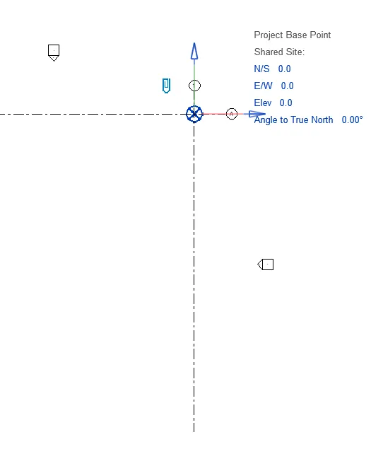
- Type 'VG' to open Visibility/Graphics
- Disable 'Project Base Point' under 'Site', click 'Apply' and then 'OK'
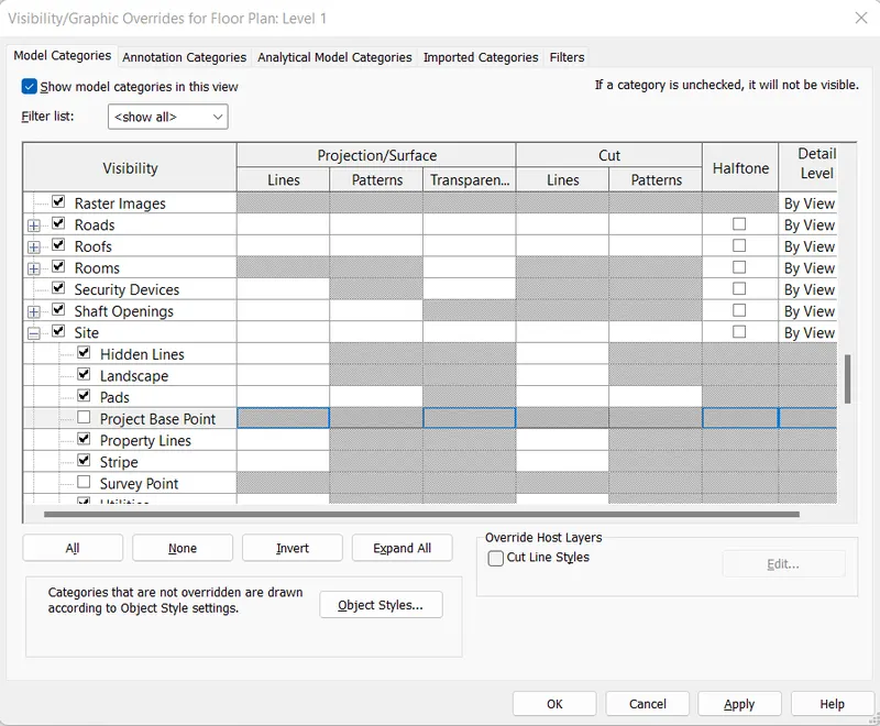
- Save the project file as 'Project Structural' and close
- Select 'Architectural Template' as the template file on 'New Project' and click 'OK'
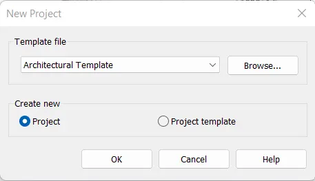
- Click 'Location' in the 'Manage' tab
- Enter the project coordinates in the 'Project Address' and click 'OK'
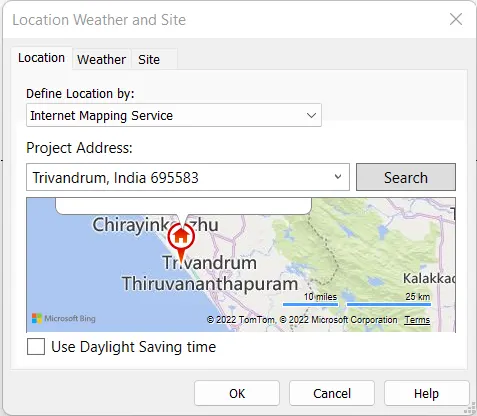
- Click 'Grids' in the 'Architecture' tab
- Draw a longitudinal grid 1
- Draw a transverse grids A
- Click 'Coordinates' in the 'Manage' tab
- Click 'Specify Coordinates at Point' under 'Coordinates'
- Click on the grids and set 'East/West: 0.0' and 'North/South: 0.0' in 'New Coordinates' under 'Specify Shared Coordinates'
- Type 'VG' to open Visibility/Graphics
- Enable 'Project Base Point' under 'Site', click 'Apply' and then 'OK'
- Click the 'Project Base Point', move it and place it in the new cordinates (N/S: 0.0, E/W: 0.0) created
- Type 'VG' to open Visibility/Graphics
- Disable 'Project Base Point' under 'Site', click 'Apply' and then 'OK'
- Save the project file as 'Project Architectural'
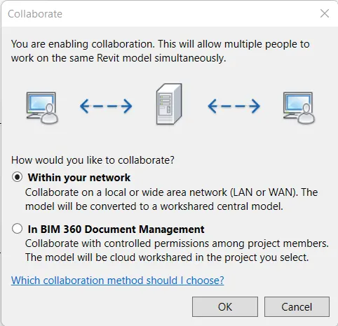
- Click 'Collaborate' in the 'Collaborate' tab
- Select 'Within your network' and click 'OK'
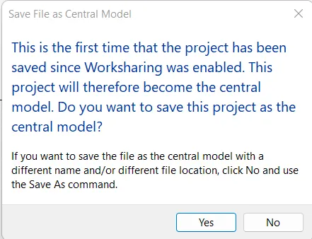
- Click 'Save' to open 'Save File as Central Model' dialogue box
- Click 'Yes'
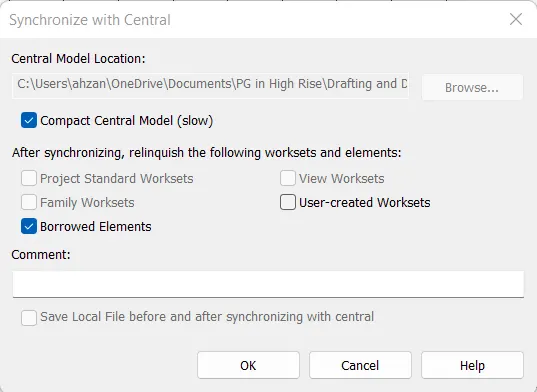
- Click 'Synchronize and Modify Settings' in the 'Synchronize with Central' under the 'Collaborate' tab
- Enable 'Compact Central Model' in the 'Synchronize with Central' and click 'OK'
- Open existing 'Project Structural' project file
- Click 'Collaborate' in the 'Collaborate' tab
- Select 'Within your network' and click 'OK'
- Click 'Save' to open 'Save File as Central Model' dialogue box
- Click 'Yes'
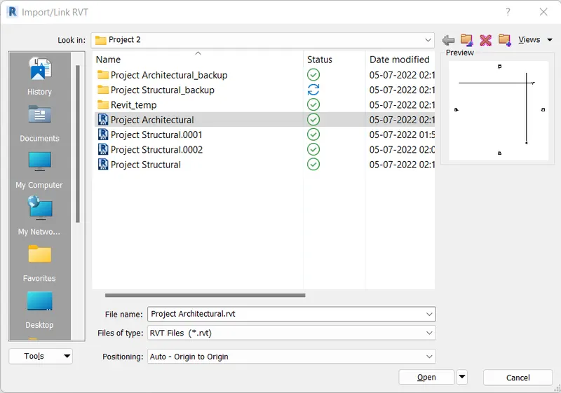
- Click 'Link Revit' in the 'Insert' tab
- Select 'Project Architectural' and click 'Open'
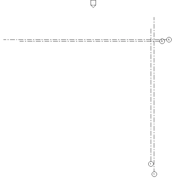
- Click 'Select Link' in the 'Copy/Monitor' under 'Collaborate' tab
- Select the link
- Click 'Copy' under the 'Copy/Monitor'
- Enable 'Multiple' option and select all the grids in the link
- Click 'Finish' option near the 'Multiple'
- Click 'Finish' under the 'Copy/Monitor'
- Select the link

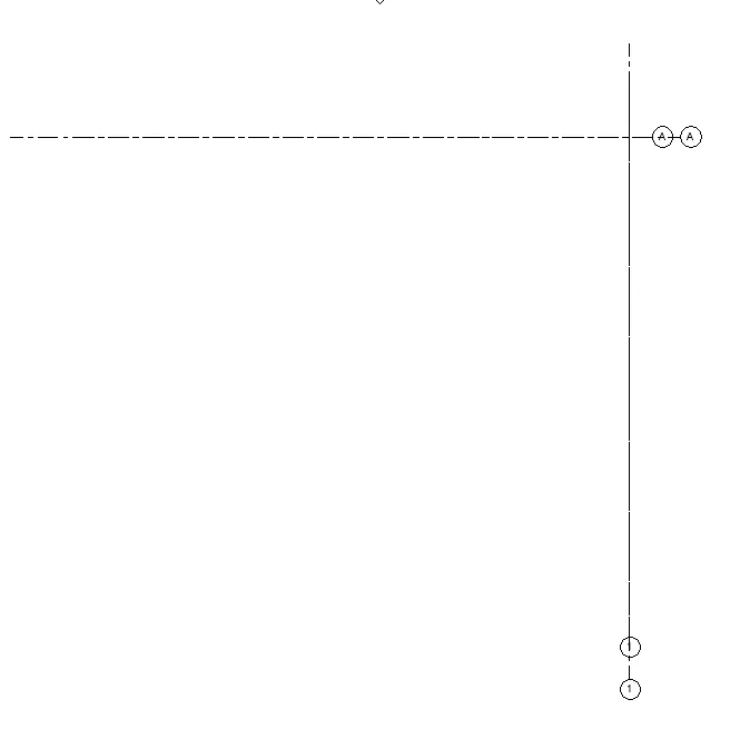
- Save and close 'Project Structural'
- Click 'New' in the 'Home'
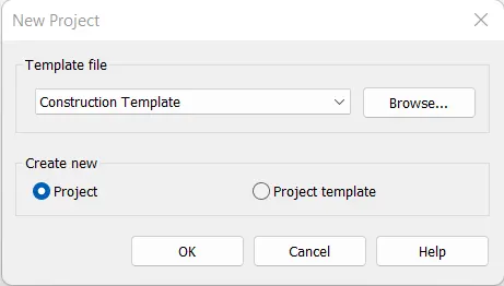
- Select 'Construction Template' as the template file on 'New Project' and click 'OK'
- Save the project file as 'Project Construction'
- Click 'Collaborate' in the 'Collaborate' tab
- Select 'Within your network' and click 'OK'
- Click 'Save' to open 'Save File as Central Model' dialogue box
- Click 'Yes'
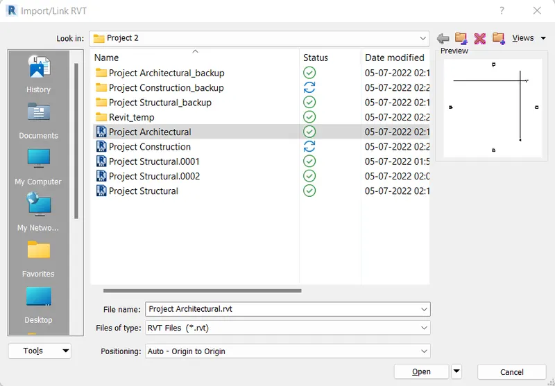
- Click 'Link Revit' in the 'Insert' tab
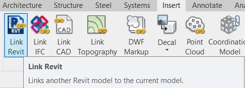
- Select 'Project Architectural' and click 'Open'
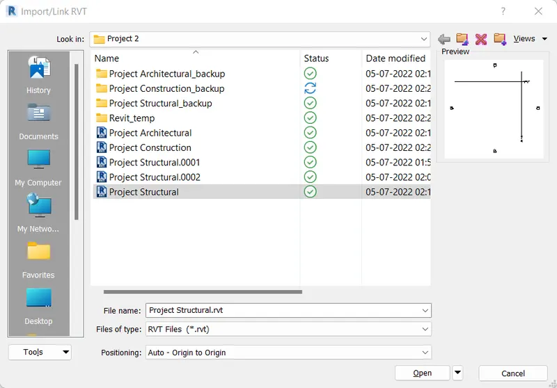
- Click 'Link Revit' in the 'Insert' tab
- Select 'Project Structural' and click 'Open'
STEP 2: Create grids and levels in Architectural and Structural Model
- Open Revit software and open existing 'Project Architectural' project file
- Click 'Grids' in the 'Architecture' tab
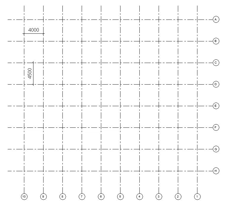
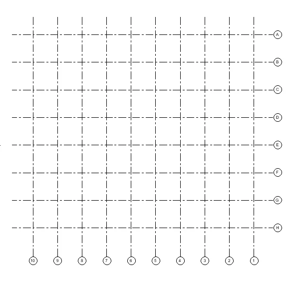
- Draw longitudinal grids 2 to 10 @ 4000mm spacing
- Select the grid 1 and 'COPY' 9 times with 4000mm spacing
- Draw transverse grids A, B, C, D, E, F, G, H @ 4500mm spacing
- Select the grid A and 'COPY' 7 times with 4500mm spacing
- Draw longitudinal grids 2 to 10 @ 4000mm spacing
- Open existing 'Project Structural' project file
- Open 'Manage Links' under 'Insert' and reload the 'Project Architectural'
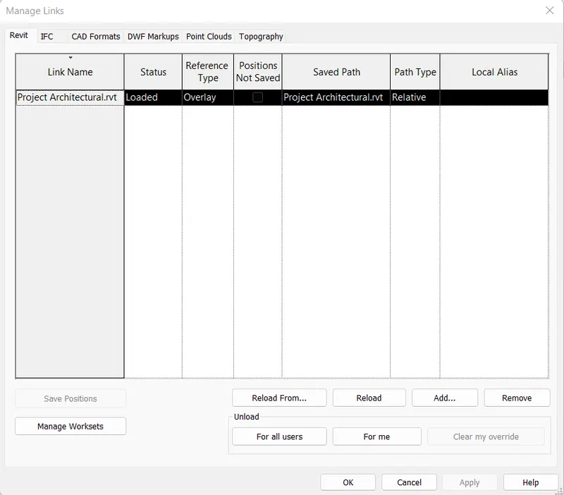
- Click 'Select Link' in the 'Copy/Monitor' under 'Collaborate' tab
- Select the link
- Click 'Copy' under the 'Copy/Monitor'
- Enable 'Multiple' option and select all the grids in the link
- Click 'Finish' option near the 'Multiple'
- Click 'Finish' under the 'Copy/Monitor'
- Select the link
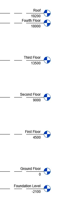
- Click 'Levels' in the 'Architecture' tab
- Add 'Foundation Level', 'Ground Floor', 'First Floor', 'Second Floor', 'Third Floor', 'Fourth Floor' and 'Roof'
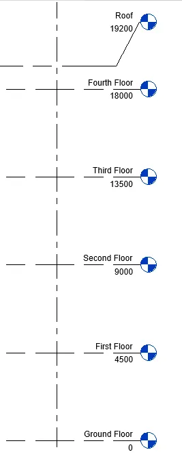
- Open existing 'Project Architectural' project file
- Click 'Levels' in the 'Architecture' tab
- Add 'Ground Floor', 'First Floor', 'Second Floor', 'Third Floor', 'Fourth Floor' and 'Roof'
STEP 3:
3. Using the structural model, include the following components based on the type of structure selected
a. Foundation – Isolated / Wall/Matt Foundation
b. Columns
c. Beams Connected to Columns
d. Roof Framing/ Truss
e. Floor / Decks
f. Floor Openings for Elevators and Stairs
The step by step procedure to create components in the structural model is following:
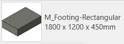
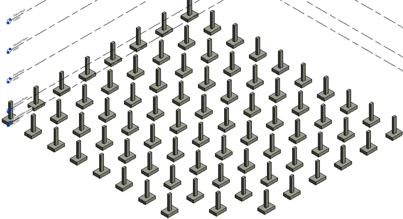
a. Foundation – Isolated Foundation
- Open existing 'Project Structural' project file
- Go to 'Project Browser', click 'Foundation Level' under the 'Structural Plans'
- Click 'Isolated' in the 'Structure' tab
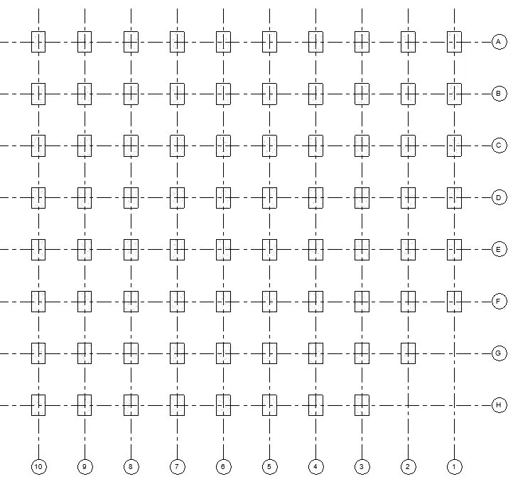
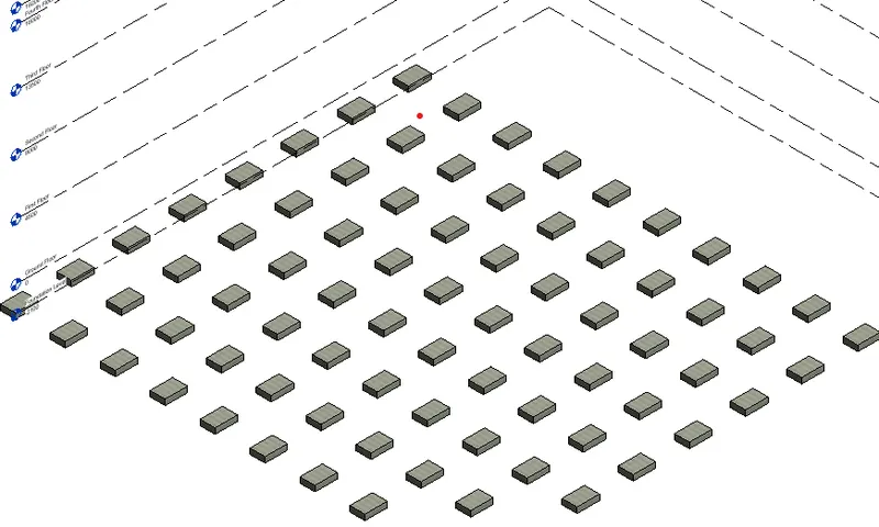
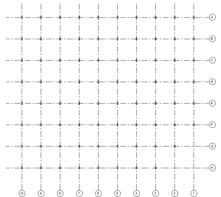
- Click 'At Grids', select all the grids and click 'Finish'
- Remove unnecessary footings
b. Columns
- Go to 'Project Browser', click 'Ground Floor' under the 'Structural Plans'
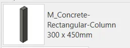
- Click 'Columns' in the 'Structure' tab
- Click 'Vertical Columns'
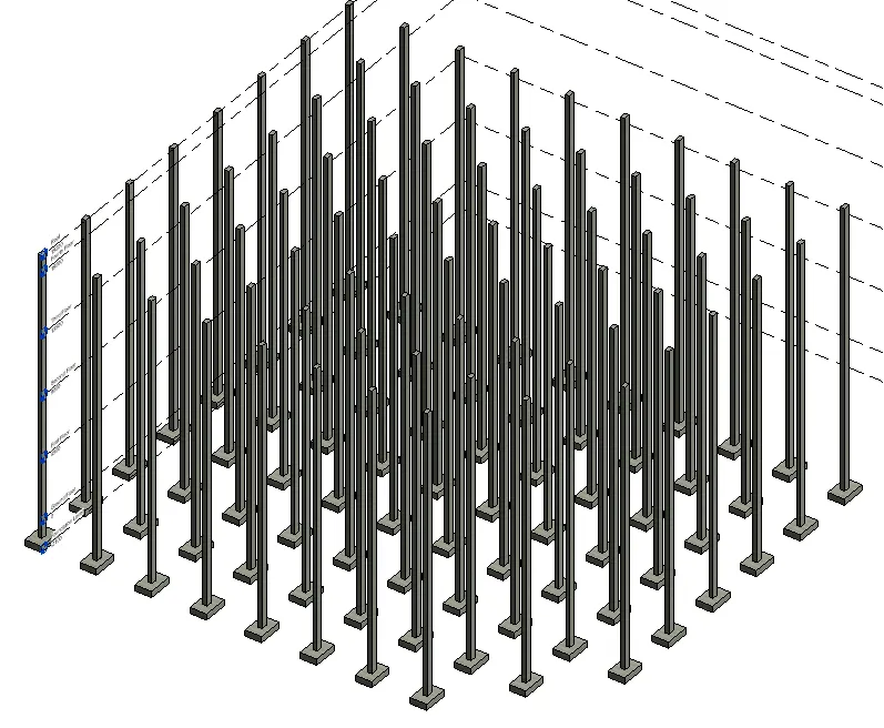
- Click 'At Grids', select all the grids and click 'Finish'
- Remove unnecessary columns
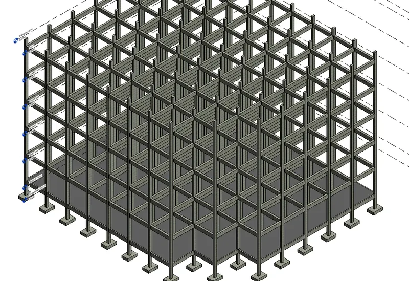
- Go to 'Properties', select all the columns and set 'Top Level' as 'Fourth Floor'
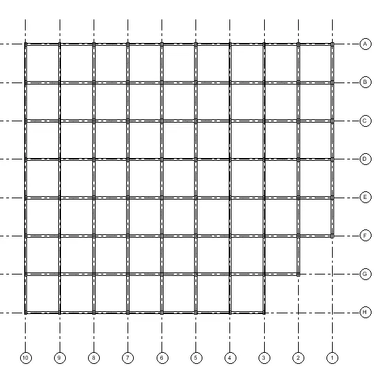
c. Beams Connected to Columns
- Go to 'Project Browser', click 'Ground Floor' under the 'Structural Plans'
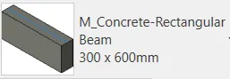
- Click 'Beams' in the 'Structure' tab
- Click 'On Grids', select all the grids and click 'Finish'
- Remove unnecessary beams
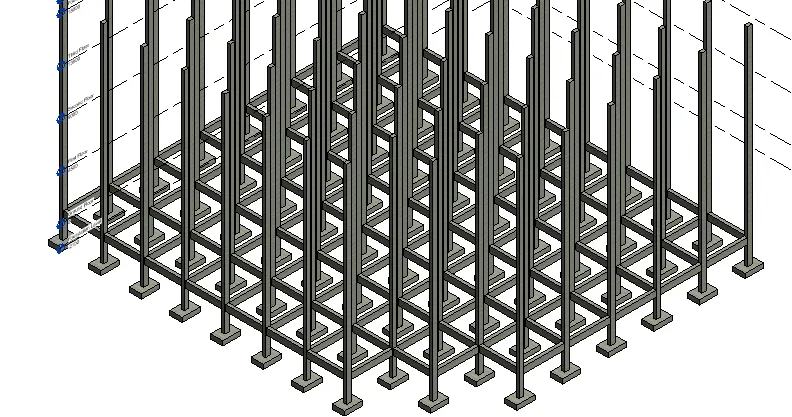
- Select one beam and turn on 'Isolate Category'
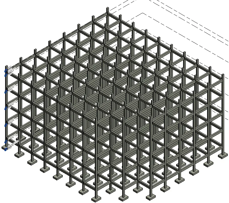
- Select all beams and click 'Copy to Clipboard' under 'Modify' tab
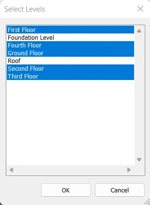
- Click 'Aligned to Selected Levels' in the 'Paste' option under 'Modify' tab
- Select 'First Floor', 'Second Floor', 'Third Floor', 'Fourth Floor' and click 'OK'
d. Roof Framing/ Truss
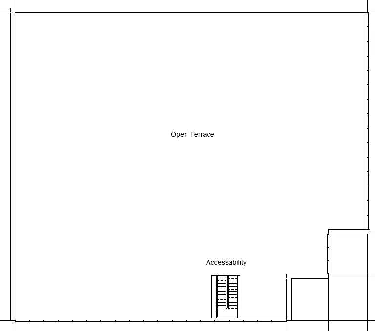
In this office building, the roof is an open terrace. So, parapet walls will be provided.
e. Floors
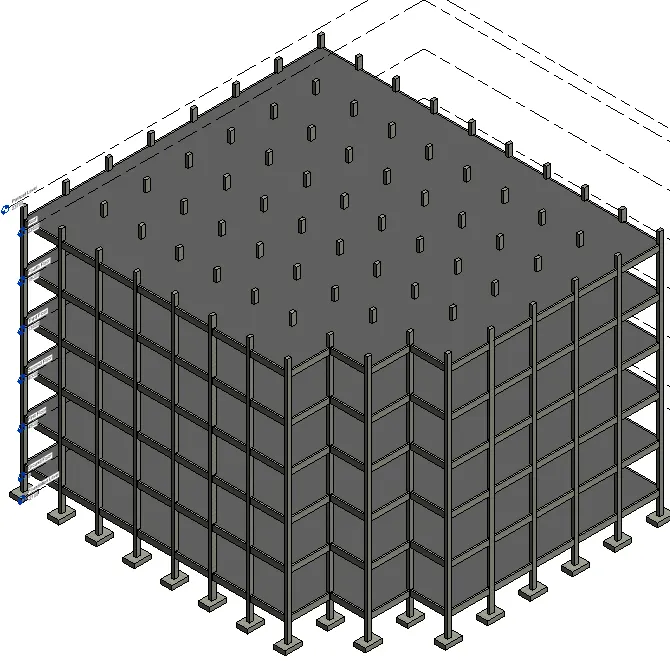
- Go to 'Project Browser', click 'Ground Floor' under the 'Structural Plans'
- Click 'Floor: Structural' in the 'Floor' under the 'Structure' tab
- Using 'Line' tool, draw the outline of the floor required
- Select the floor and click 'Copy to Clipboard' under 'Modify' tab
- Click 'Aligned to Selected Levels' in the 'Paste' option under 'Modify' tab
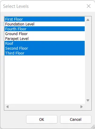
- Select 'First Floor', 'Second Floor', 'Third Floor', 'Fourth Floor', 'Roof' and click 'OK'
f. Floor Openings for Elevators and Stairs
- Go to 'Project Browser', click 'Ground Floor' under the 'Structural Plans'
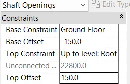
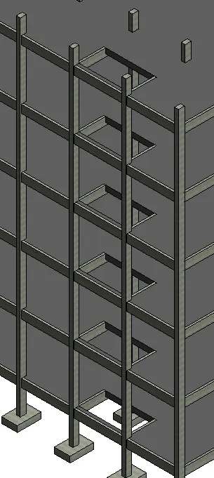
- Click the 'Shaft' under the 'Structure' tab
- Using 'Line' tool, draw the outline of the shaft opening required
STEP 4:
4. Using the architectural model, include the following components based on the type of structure selected
a. Wall Layout with appropriate material and finishing
b. Exterior façade with fancy finish
c. Interior partition walls to size rooms
d. Components to add details to a room ( Desk, Chair, Lighting, Plumbing fixtures)
e. Add components such as stairs Elevators
f. Have at-least one side of the building with curtain walls and glass panels
g. Include interior and exterior lighting fixtures
h. Place proper topographic components from outside ( Trees, Parking, Plants) to add details to the model
The step by step procedure to create components in the architectural model is following:
a. Wall Layout with appropriate material and finishing
- Open existing 'Project Architectural' project file
- Go to 'Project Browser', click 'Ground Floor' under the 'Floor Plans'
- Click 'Wall' in the 'Architecture' tab
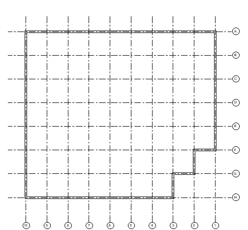
- Draw the wall layout using 'Line' tool
- Go to 'Properties', select all the walls and set 'Top Constraints- Upto Level: Parapet wall'
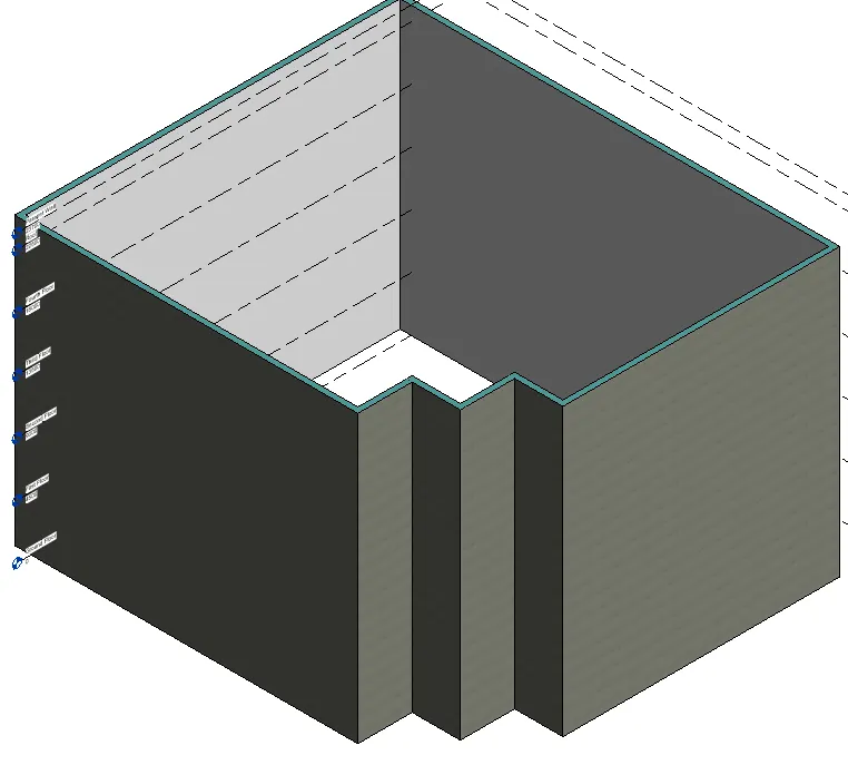
b. Exterior façade with fancy finish
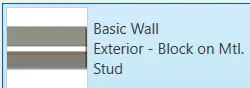
- Go to 'Properties', select all the walls and click 'Edit Type'
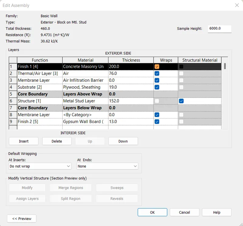
- Click 'Edit..' in the 'Structure' under the 'Type Properties'
- Click the three dots near the 'By Category' under the 'Edit Assembly'
- Assign appropriate material under 'Material Browser' and click 'OK'
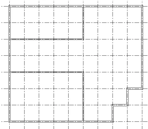
c. Interior partition walls to size rooms
- Go to 'Project Browser', click 'Ground Floor' under the 'Floor Plans'
- Click 'Wall' in the 'Architecture' tab
- Draw the wall using 'Line' tool
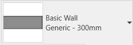
- Go to 'Properties', select all the walls and click 'Edit Type'
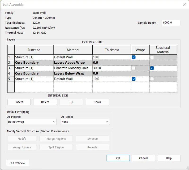
- Click 'Edit..' in the 'Structure' under the 'Type Properties'
- Click the three dots near the 'By Category' under the 'Edit Assembly'
- Assign appropriate material under 'Material Browser' and click 'OK'
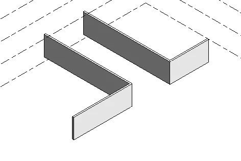
- Go to 'Project Browser', click 'First Floor' under the 'Floor Plans'
- Click 'Wall' in the 'Architecture' tab
- Draw the wall using 'Line' tool
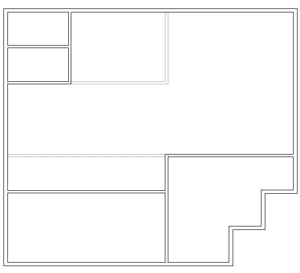
- Go to 'Properties', select all the walls and click 'Edit Type'
- Click 'Edit..' in the 'Structure' under the 'Type Properties'
- Click the three dots near the 'By Category' under the 'Edit Assembly'
- Assign appropriate material under 'Material Browser' and click 'OK'
- Click 'Wall' in the 'Architecture' tab
- Draw the wall using 'Line' tool
- Go to 'Properties', select all the partition walls
- Set 'Top Offset: -2500'
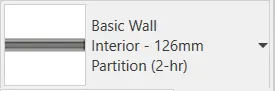
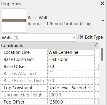
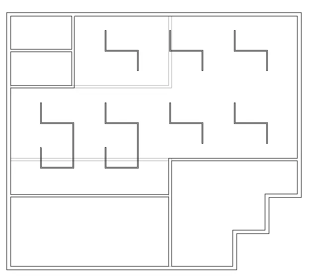
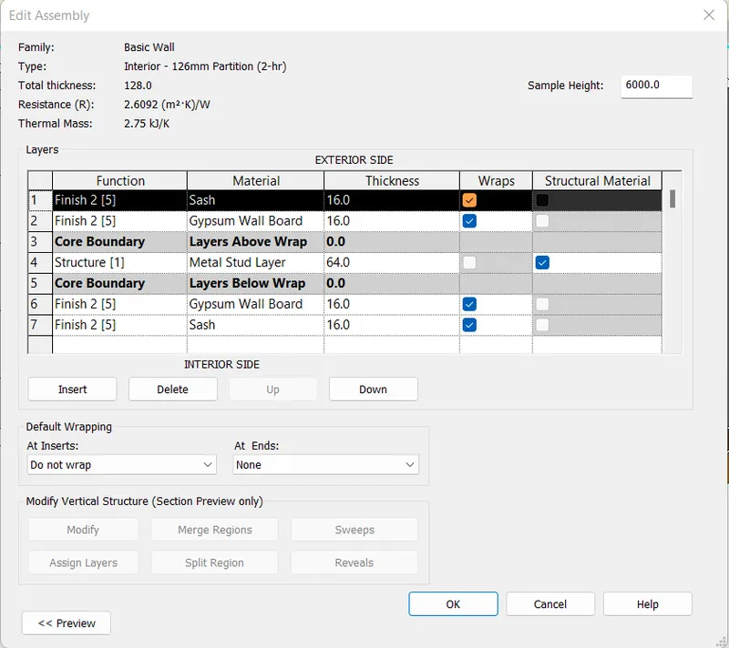
- Go to 'Properties', select all the partition walls and click 'Edit Type'
- Click 'Edit..' in the 'Structure' under the 'Type Properties'
- Click the three dots near the 'By Category' under the 'Edit Assembly'
- Assign appropriate material under 'Material Browser' and click 'OK'
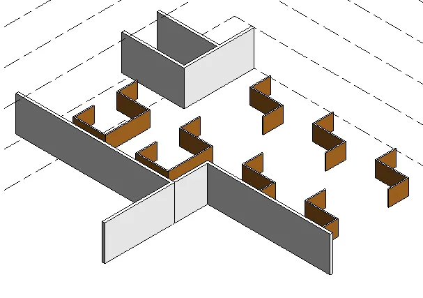
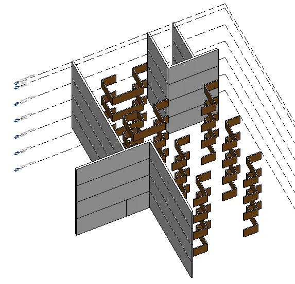
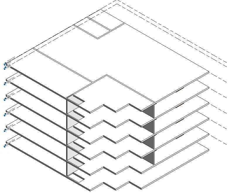
- Select the walls in the First Floor and click 'Copy to Clipboard' under 'Modify' tab
- Click 'Aligned to Selected Levels' in the 'Paste' option under 'Modify' tab
- Select 'Second Floor', 'Third Floor', 'Fourth Floor' and click 'OK'
- Turn on 'Revit Link' in 'VG'
- Click 'Select Link' in the 'Copy/Monitor' under 'Collaborate' tab
- Select the link
- Click 'Copy' under the 'Copy/Monitor'
- Enable 'Multiple' option and select all the floors in the link
- Click 'Finish' under the 'Copy/Monitor'
- Select the link
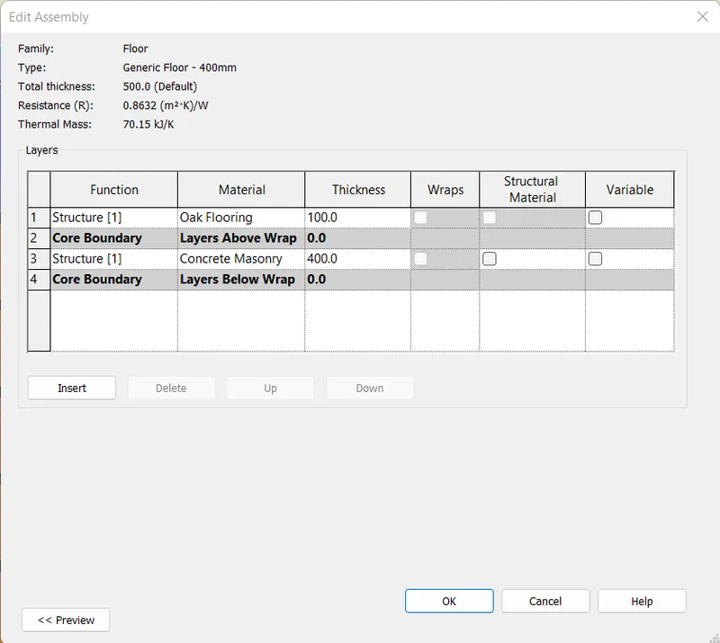
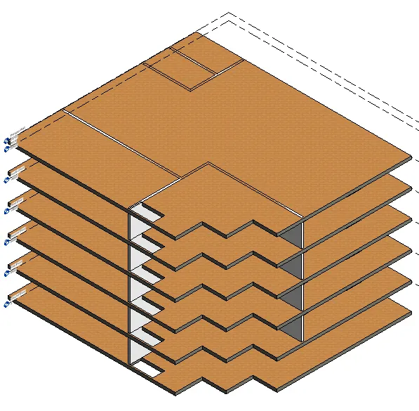
- Go to 'Properties', select all the floors and click 'Edit Type'
- Click 'Edit..' in the 'Structure' under the 'Type Properties'
- Click the three dots near the 'By Category' under the 'Edit Assembly'
- Assign appropriate material under 'Material Browser' and click 'OK'
d. Components to add details to a room ( Desk, Chair, Lighting, Plumbing fixtures)
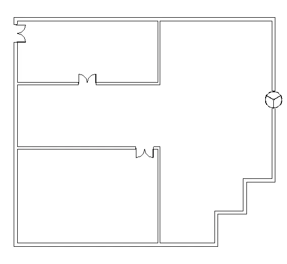
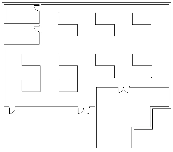
a) Doors
- Select 'Door' in the 'Architecture' tab
- Click on the 'Load Family'
- Open 'Doors' category under 'US Imperial'
- Open 'Commercial' family under 'Doors' category
- Select any door under 'Commercial' family and click 'Open'
- Select any type of door in the door family and click 'OK'
- Place the door
- Repeat the above steps and place any type of doors in the plan as needed
Ground Floor
First Floor, Second Floor, Third Floor, Fourth Floor
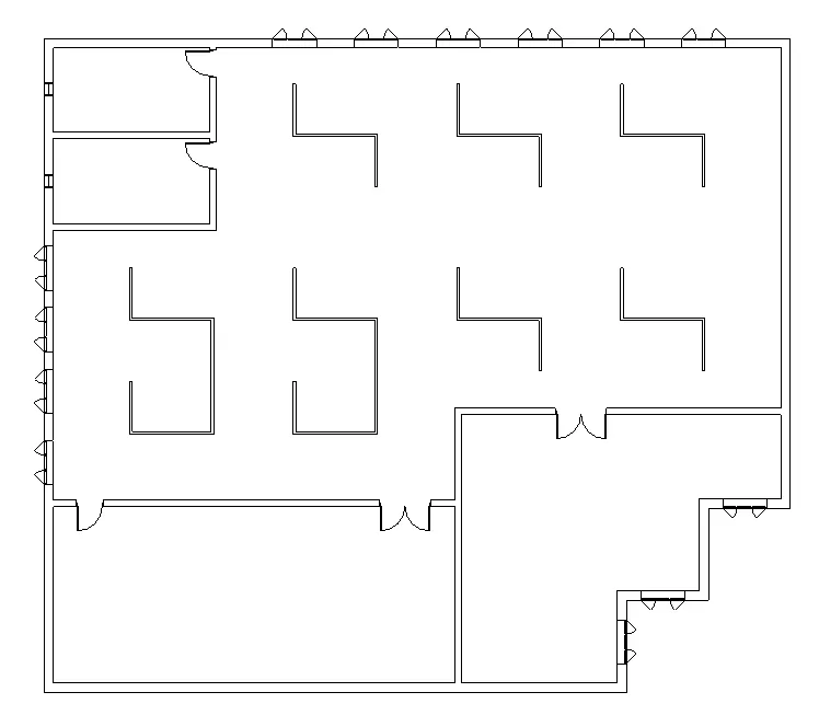
b) Windows
- Select 'Window' in the 'Architecture' tab
- Open 'Windows' category under 'US Imperial'
- Select any window under 'Windows' category and click 'Open'
- Select any type of window in the window family and click 'OK'
- Place the windows
- Repeat the above steps and place any type of windows in the plan as needed
Ground Floor

First Floor, Second Floor, Third Floor, Fourth Floor
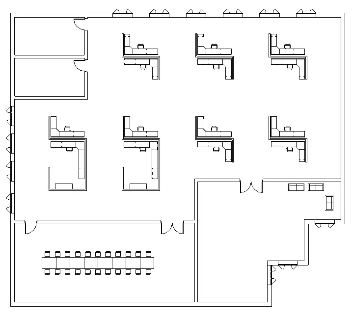
3) Furniture
- Select 'Component' in the 'Architecture' tab
- Open 'Furniture' category under 'US Imperial'
- Open 'Tables' family under 'Furniture' category
- Select any desk under 'Tables' family and click 'Open'
- Place the desk
- Repeat the above steps and place any type of desk/table in the plan as needed
- Select 'Component' in the 'Architecture' tab
- Open 'Casework' category under 'US Imperial'
- Open 'Base Cabinet' family under 'Casework' category
- Select any desk cabinet 'Base Cabinet' family and click 'Open'
- Place the base cabinet
- Repeat the above steps and place any type of base cabinet in the plan as needed
- Select 'Component' in the 'Architecture' tab
- Open 'Furniture' category under 'US Imperial'
- Open 'Seating' family under 'Furniture' category
- Select any chair under 'Seating' family and click 'Open'
- Place Chairs
- Repeat the above steps and place any type of chairs in the plan as needed
Ground Floor
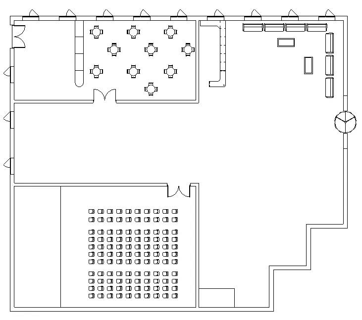
First Floor, Second Floor, Third Floor, Fourth Floor
4) Plumbing fixtures
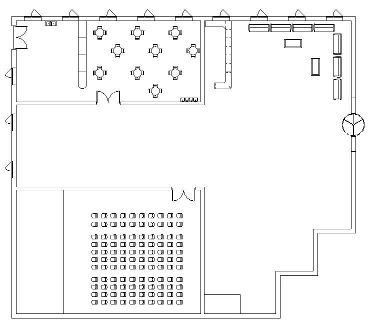
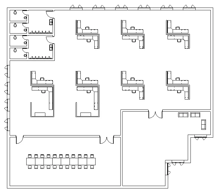
Readjusted the toilets into 4 compartments
- Select 'Component' in the 'Architecture' tab
- Open 'Plumbing' category under 'US Imperial'
- Open 'Architectural-Fixtures' family under 'Plumbing' category
- Open 'Water Closets' family under 'Fixtures' Family
- Select any closet under 'Fixtures' Family and click 'Open'
- Place the closets in the toilets
- Repeat the above steps and place any type of closets in the plan as needed
- Select 'Component' in the 'Architecture' tab
- Open 'Plumbing' category under 'US Imperial'
- Open 'Architectural-Fixtures' family under 'Plumbing' category
- Open 'Urinals' family under 'Fixtures' Family
- Select any urinal under 'Fixtures' Family and click 'Open'
- Place the urinals in the toilets
- Select 'Component' in the 'Architecture' tab
- Open 'Plumbing' category under 'US Imperial'
- Open 'Architectural-Fixtures' family under 'Plumbing' category
- Open 'Sinks' family under 'Fixtures' Family
- Select any sink under 'Fixtures' Family and click 'Open'
- Place the sinks in the toilets
- Repeat the above steps and place any type of sink in the plan as needed
Ground Floor
First Floor, Second Floor, Third Floor, Fourth Floor
5) Lighting
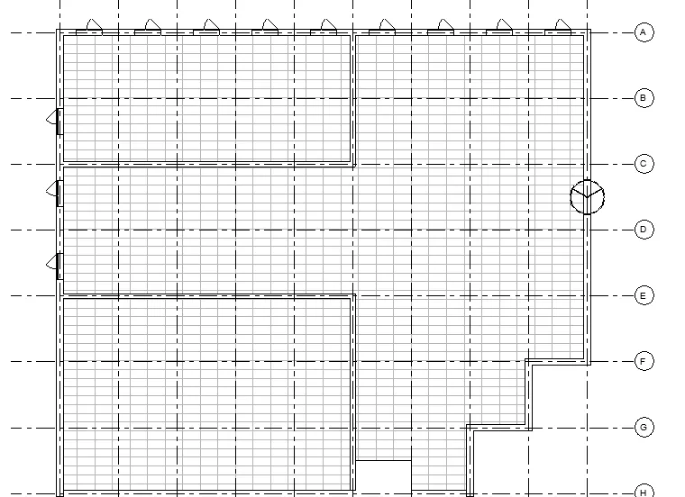
- Go to 'Project Browser', click 'Ground Floor' under the 'Ceiling Plans'
- Click 'Ceiling' under the 'Architecture' tab
- Using 'Line' tool, draw the outline of the ceiling required
- Select the Ceiling and click 'Copy to Clipboard' under 'Modify' tab
- Click 'Aligned to Selected Levels' in the 'Paste' option under 'Modify' tab
- Select 'First Floor', 'Second Floor', 'Third Floor', 'Fourth Floor' and click 'OK'
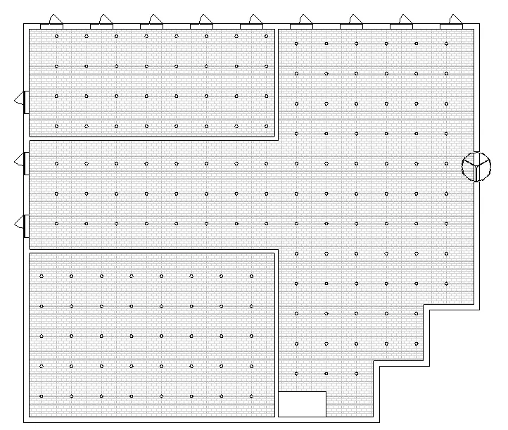
- Select 'Component' in the 'Architecture' tab
- Open 'Lighting' category under 'US Imperial'
- Open 'Architectural-Internal' family under 'Lighting' category
- Select any light under 'Architectural-Internal' family and click 'Open'
- Place lights
Ground Floor
First Floor, Second Floor, Third Floor, Fourth Floor
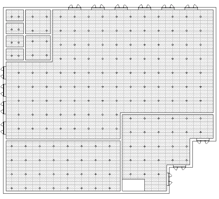
e. Add components such as stairs Elevators
1) Stairs
- Go to 'Project Browser', click 'Ground Floor' under the 'Floor Plans'
- Select 'Stair' in the 'Architecture' tab
- Draw stairs from ground floor to roof
- Re-adjust the shaft opening according to the stairs
Ground Floor
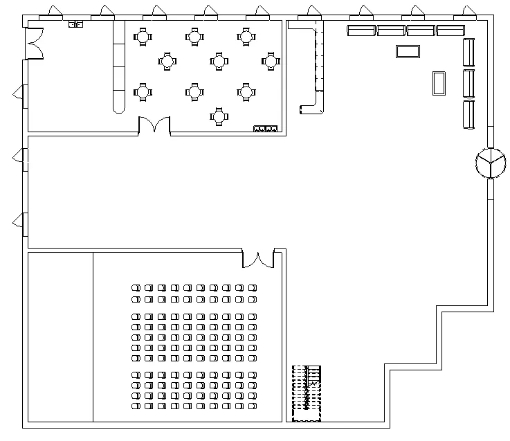
First Floor, Second Floor, Third Floor, Fourth Floor
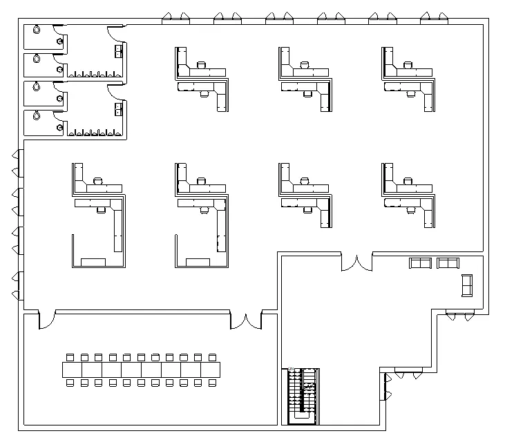
2) Elevator
- Select 'Wall' in the 'Architecture' tab
- Draw walls for elevators
- Select 'Component' in the 'Architecture' tab
- Open 'Speciality Equipment' category under 'US Imperial'
- Open 'Elevators and Lifts' family under 'Speciality Equipment' category
- Select any lift wall based under 'Elevators and Lifts' family and click 'Open'
- Place lifts
- Select 'Shaft' in the 'Architecture' tab
- Draw shaft for lift from Ground Floor to Fourth Floor
Ground Floor
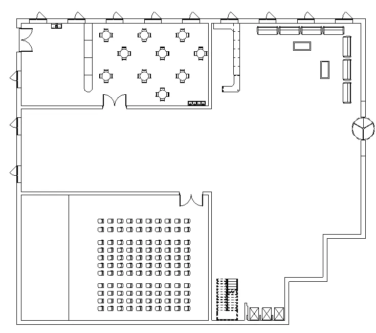
First Floor, Second Floor, Third Floor, Fourth Floor
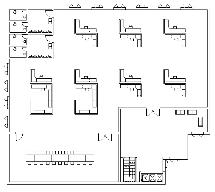
f. Have at-least one side of the building with curtain walls and glass panels
- Go to 'Properties', select all the walls
- Change the wall type to 'Storefront' from 'Curtain Wall'
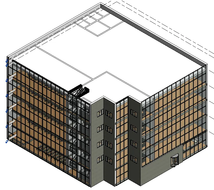
g. Include interior and exterior lighting fixtures
- Interior lighting fixtures are already provided in the above step (d)
- Exterior lighting fixtures will be provided in the next step (h)
h. Place proper topographic components from outside ( Trees, Parking, Plants) to add details to the model
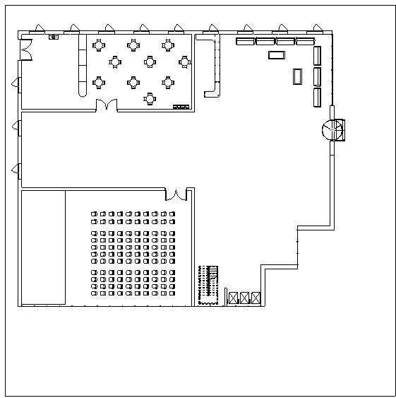
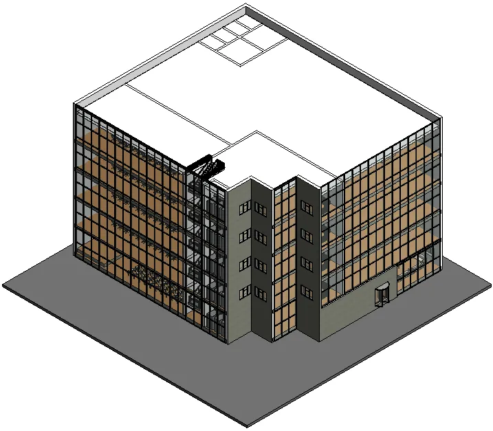
1) Site
- Go to 'Project Browser', click 'Ground Floor' under the 'Floor Plans'
- Select 'Floor' in the 'Architecture' tab
- Draw plot size 45mx45m
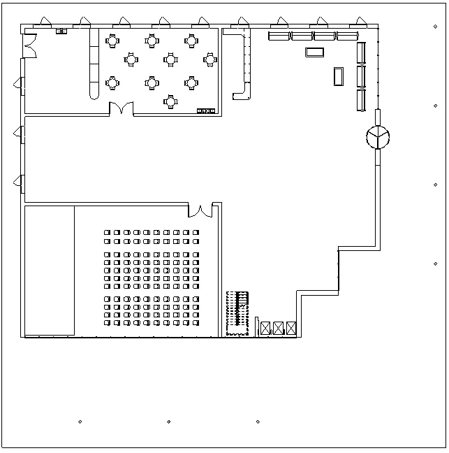
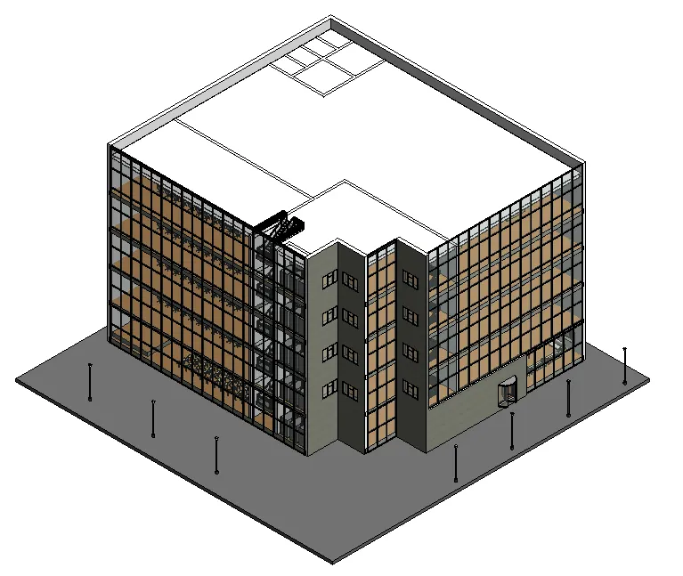
2) Exterior Lighting
- Select 'Component' in the 'Architecture' tab
- Open 'Lighting' category under 'US Imperial'
- Open 'Architectural-External' family under 'Lighting' category
- Select any light under 'Architectural-External' family and click 'Open'
- Place lights
3) Trees
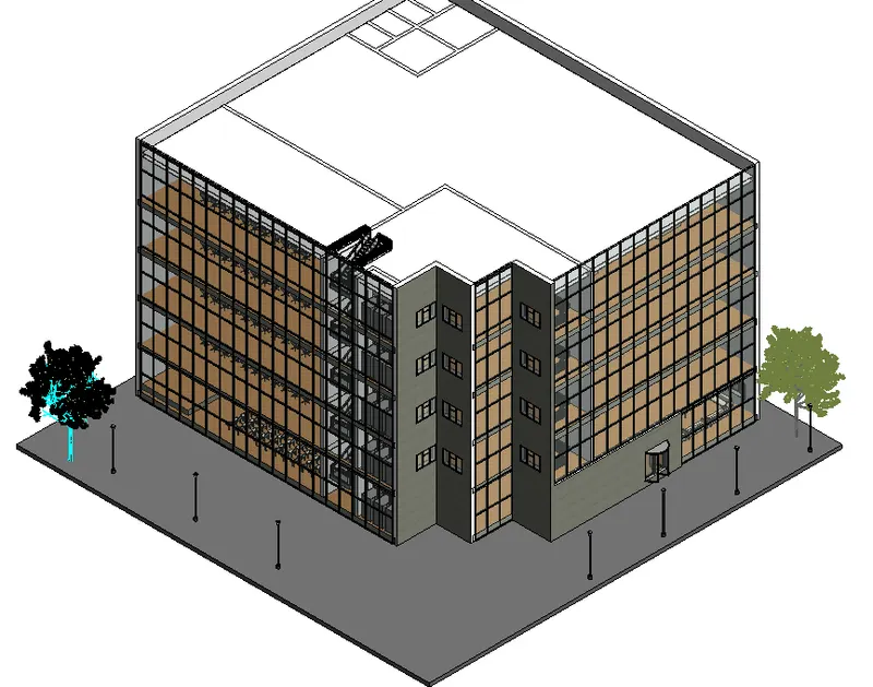
- Select 'Site Component' under the 'Massing & Site' tab
- Click 'Load Family'
- Select the tree family downloaded and click 'OK'
- Place the trees
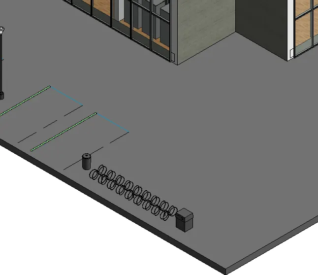
4) Parking
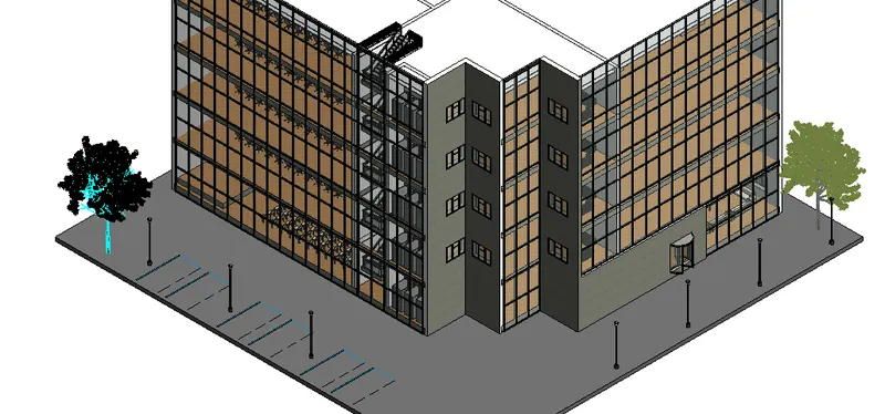
- Select 'Parking Component' under the 'Massing & Site' tab
- Place the parking lot
5) Sustainable Design
- Select 'Component' in the 'Architecture' tab
- Open 'Sustainable Design' category under 'US Imperial'
- Select any design under 'Sustainable Design' category and click 'Open'
- Place the designs
STEP 5:
5. Provide a set of drawings in an architectural and structural model to list the following details with categories and appropriate sheet templates included
a. Floor Plans with Annotations
b. Elevations
c. Sections
The step by step procedure to create drawing sheets for the architectural and structural model is following:
a. Floor Plans with Annotations
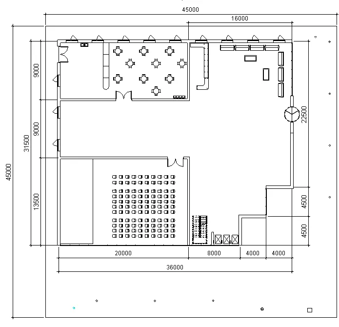
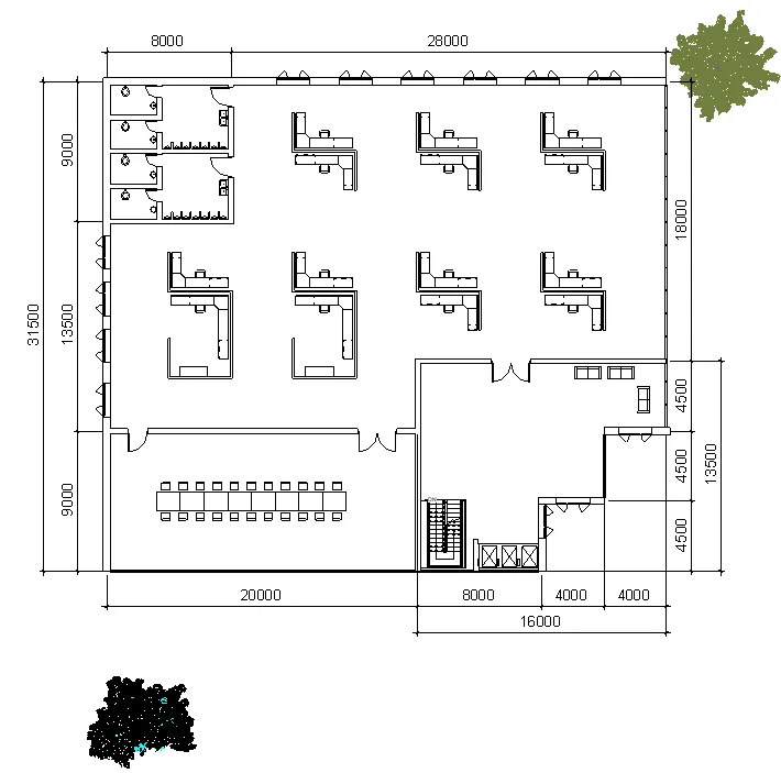
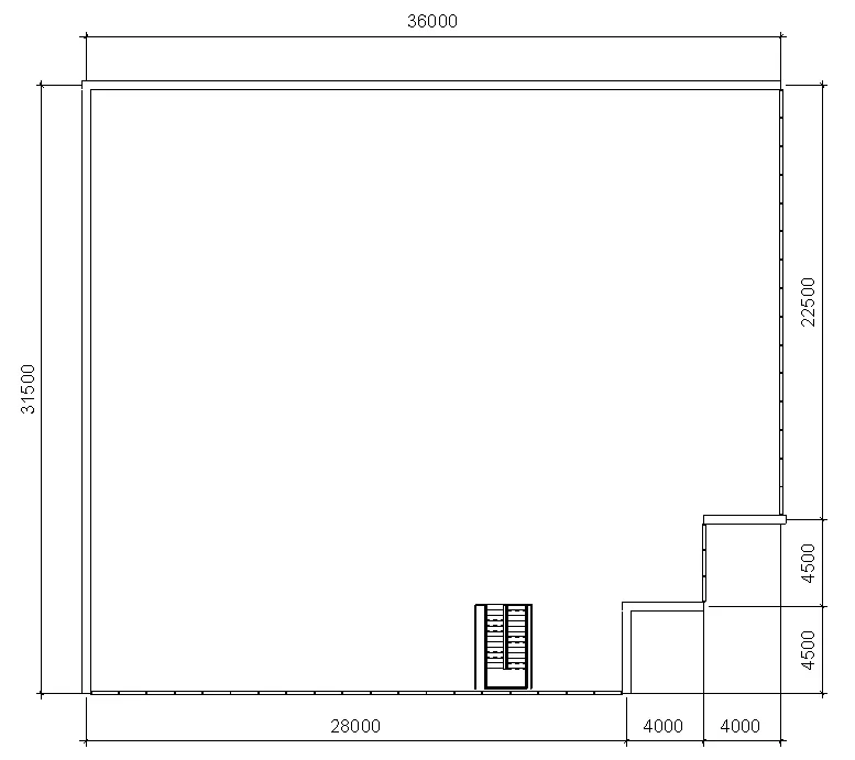
1) Dimensions
- Select 'Aligned' in the 'Annotate' tab
- Mark all necessary dimensions in the floor plans
- All dimensions are in Millimeters
Ground Floor
First Floor, Second Floor, Third Floor, Fourth Floor
Roof Level
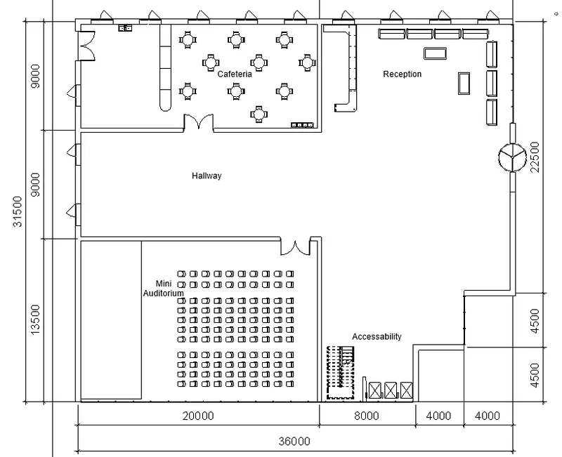
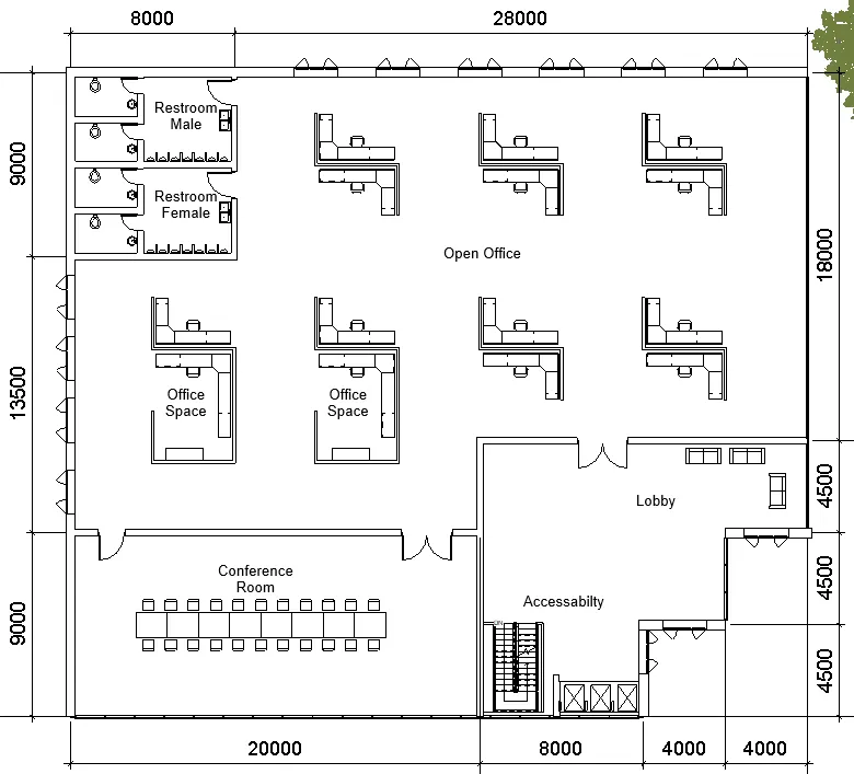
2) Room Tags
- Select 'Room' in the 'Architecture' tab
- Mark all the rooms in the floor plan
- Rename the rooms to appropriate names
Ground Floor
First Floor, Second Floor, Third Floor, Fourth Floor
Roof Level
3) Drawing sheets
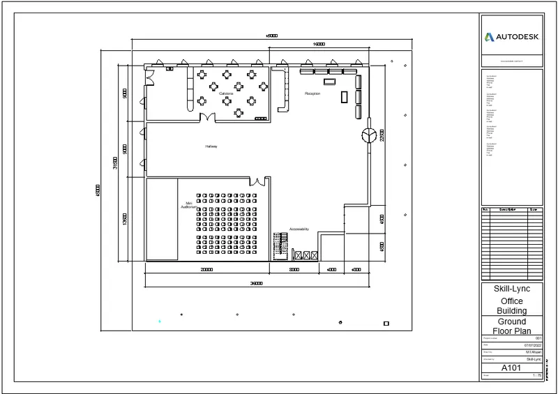
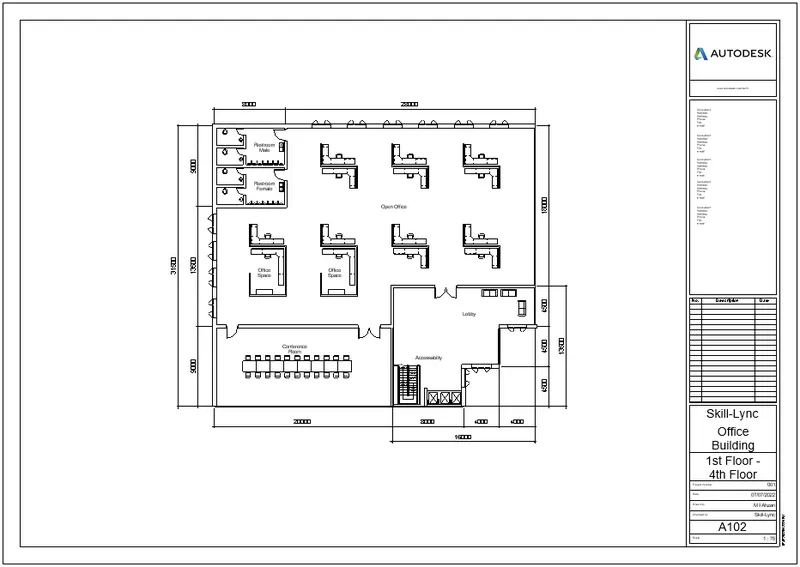
a. Floor Plans with Annotations
- Select 'Sheet' in the 'View' tab
- Select 'A0 metric' and click 'OK'
- Change the contents in the sheet by double clicking the subject
- Drag the all the floor plans to the sheet from 'Project Browser' under 'Floor Plans'
- Adjust 'Scale Value 1:75' in the 'Project Browser'
Ground Floor
First Floor, Second Floor, Third Floor, Fourth Floor
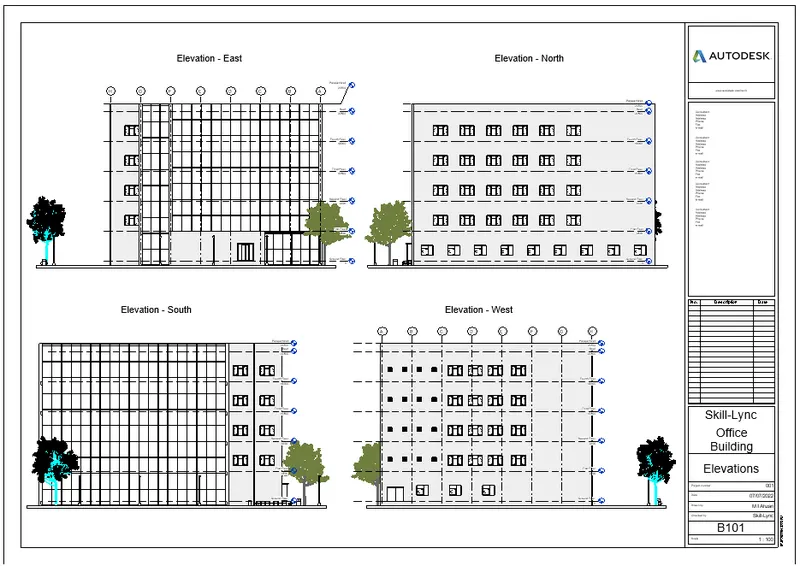
b. Elevations
- Select 'Sheet' in the 'View' tab
- Select 'A0 metric' and click 'OK'
- Change the contents in the sheet by double clicking the subject
- Drag the all the elevations to the sheet from 'Project Browser' under 'Elevation'
- Adjust 'Scale Value 1:100' in the 'Project Browser'
- Select 'Text' in the 'Annotate' tab
- Type the necessary texts and place it in the sheet
c. Sections
- Select 'Section' in the 'View' tab
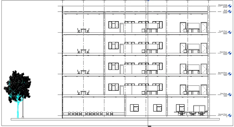
- Draw X and Y sections namely section 1 and section 2 respectively
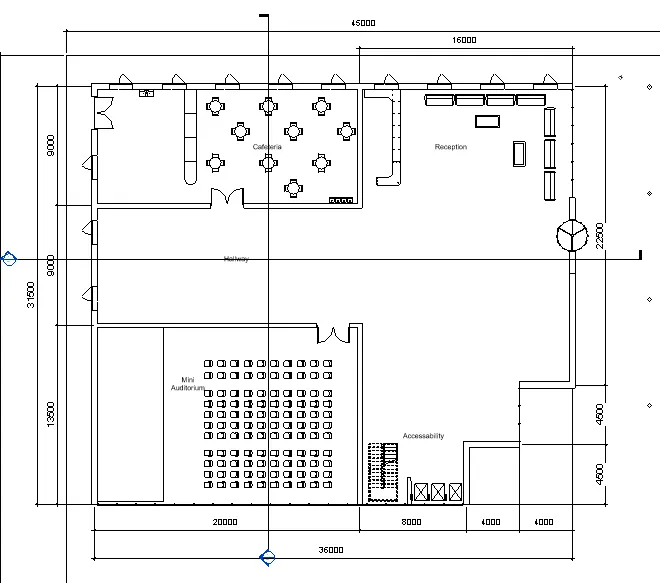
Section 1
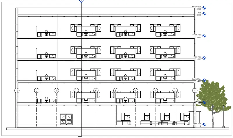
Section 2
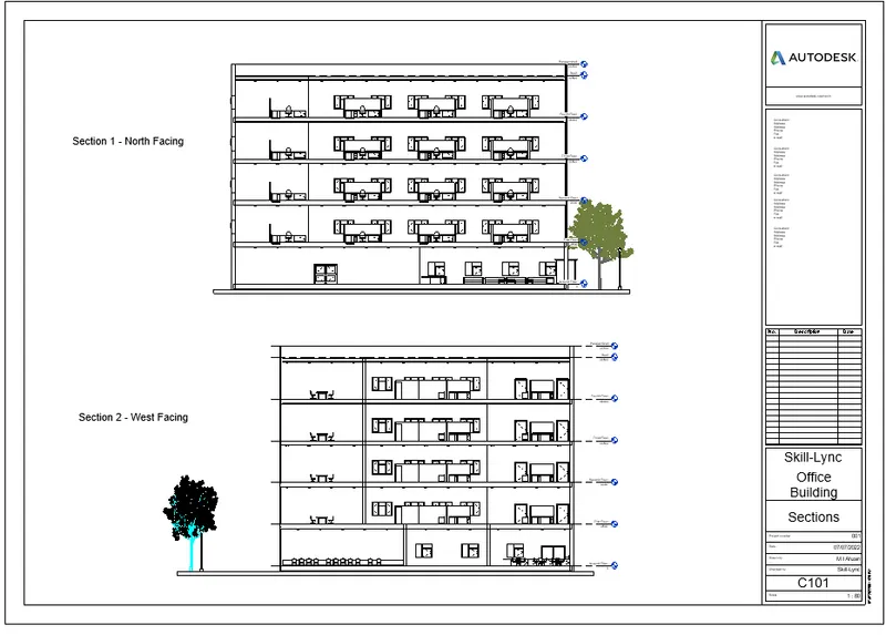
- Select 'Sheet' in the 'View' tab
- Select 'A0 metric' and click 'OK'
- Change the contents in the sheet by double clicking the subject
- Drag the all the sections to the sheet from 'Project Browser' under 'Sections'
- Adjust 'Scale Value 1:100' in the 'Project Browser'
- Select 'Text' in the 'Annotate' tab
- Type the necessary texts and place it in the sheet
STEP 6:
6. Using the Rendering settings, Render images of the 3D model produced and include the rendered images to the drawing sheets
a. Rendering from interior rooms
b. Rendering from out showing topographic features
c. Rendering through structural framing
The step by step procedure to create drawing sheets for the rendered images of the 3D model is following:
a. Rendering from interior rooms
1) Ground Floor Interior
- Select 'Camera' in the '3D View' under the 'View' tab
- Use camera to show the interior of the rooms
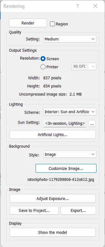
- Select 'Render' under the 'View' tab
- Set 'Quality - Setting: Medium'
- Set 'Lighting - Scheme: Interior: Sun and Architectural'
- *For each view, the settings maybe changed for a better output
- Set 'Background - Style: Image'
- *For each view, the settings maybe changed for a better output
- Click 'Adjust Exposure' under 'Image' and set accordingly
- Click 'Save to Project' under 'Image'
- Click 'Render'
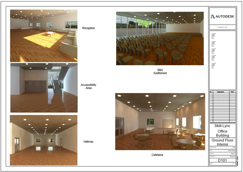
Reception
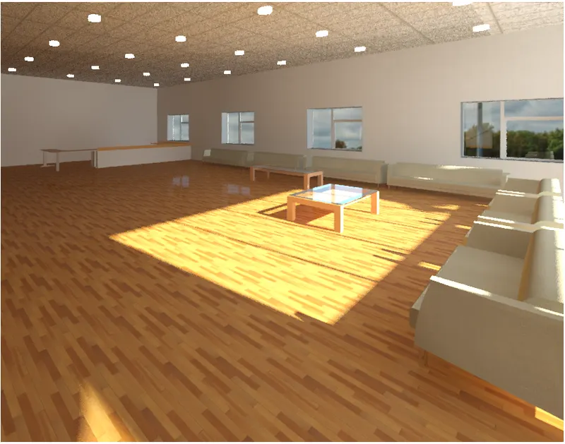
Accessibilty Area
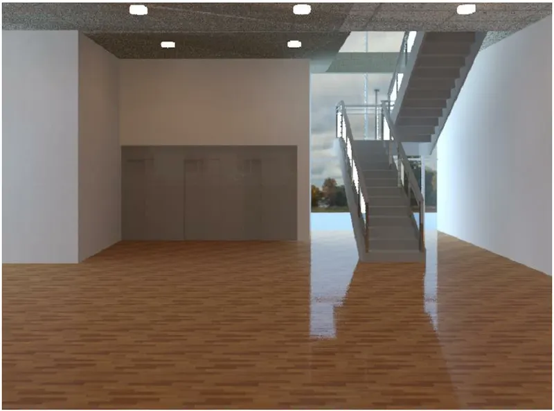
Hallway
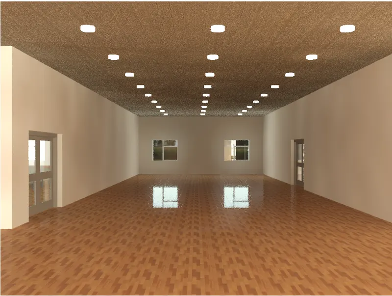
Mini Auditorium
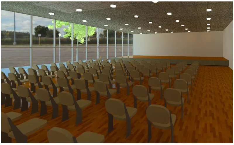
Cafeteria
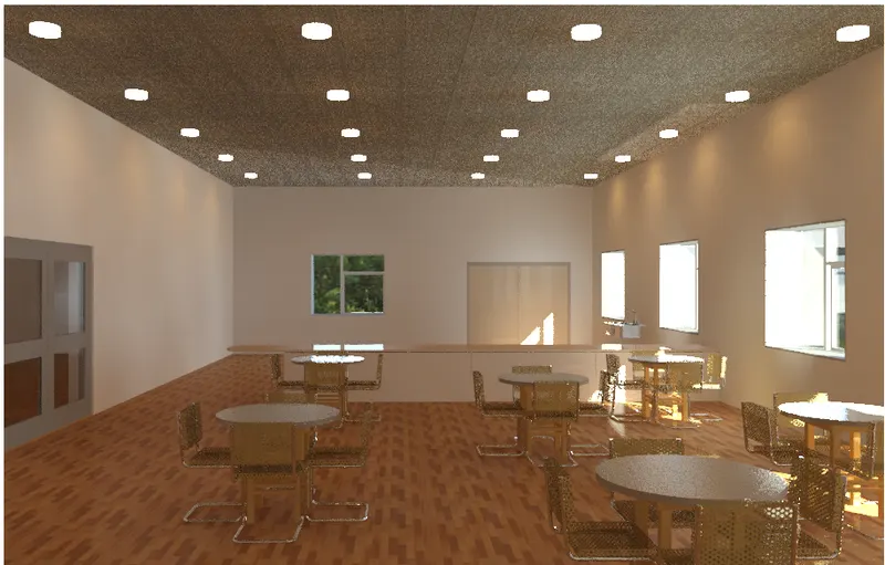
- Select 'Sheet' in the 'View' tab
- Select 'A0 metric' and click 'OK'
- Change the contents in the sheet by double clicking the subject
- Drag the all the Ground Floor Rendered 3D images to the sheet from 'Project Browser' under 'Renderings'
- Adjust the image inside the sheet
- Select 'Text' in the 'Annotate' tab
- Type the necessary texts and place it in the sheet
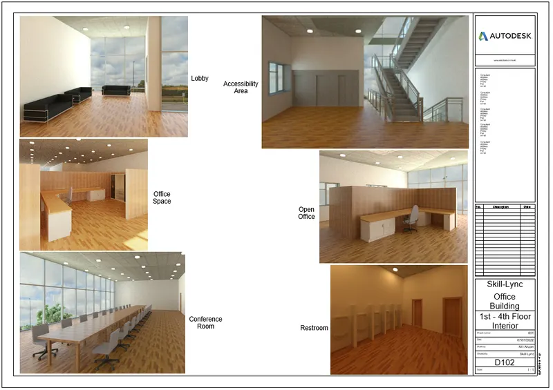
2) First, Second, Third and Fourth Floor Interior
- Select 'Camera' in the '3D View' under the 'View' tab
- Use camera to show the interior of the rooms
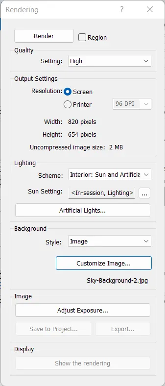
- Select 'Render' under the 'View' tab
- Set 'Quality - Setting: High'
- Set 'Lighting - Scheme: Interior: Sun and Architectural'
- *For each view, the settings maybe changed for a better output
- Set 'Background - Style: Image'
- *For each view, the settings maybe changed for a better output
- Click 'Adjust Exposure' under 'Image' and set accordingly
- Click 'Save to Project' under 'Image'
- Click 'Render'
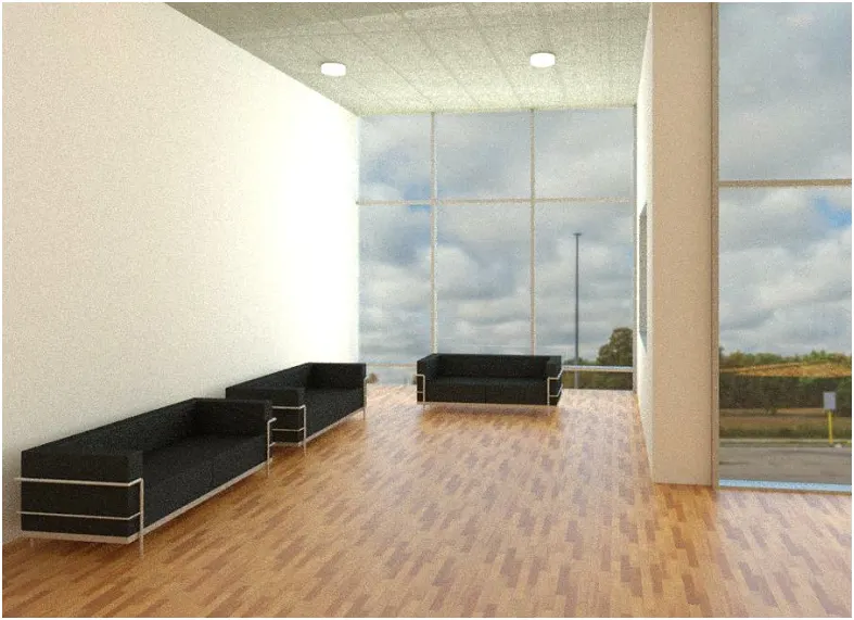
Lobby
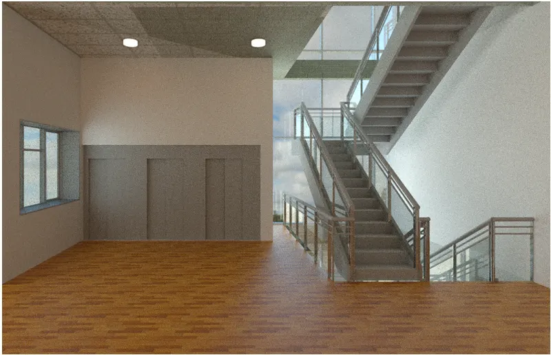
Accessibility Area
Open Office
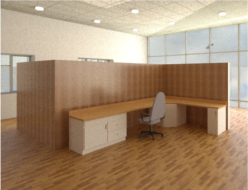
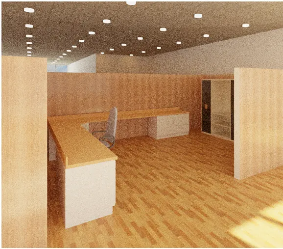
Office Space
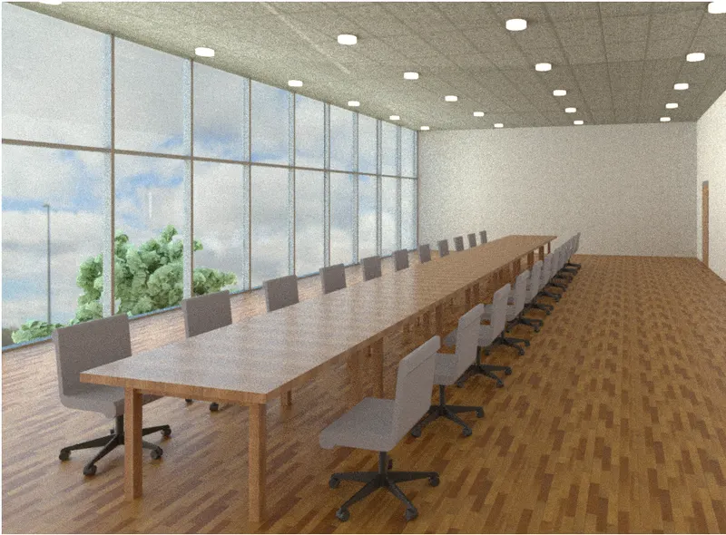
Conference Room
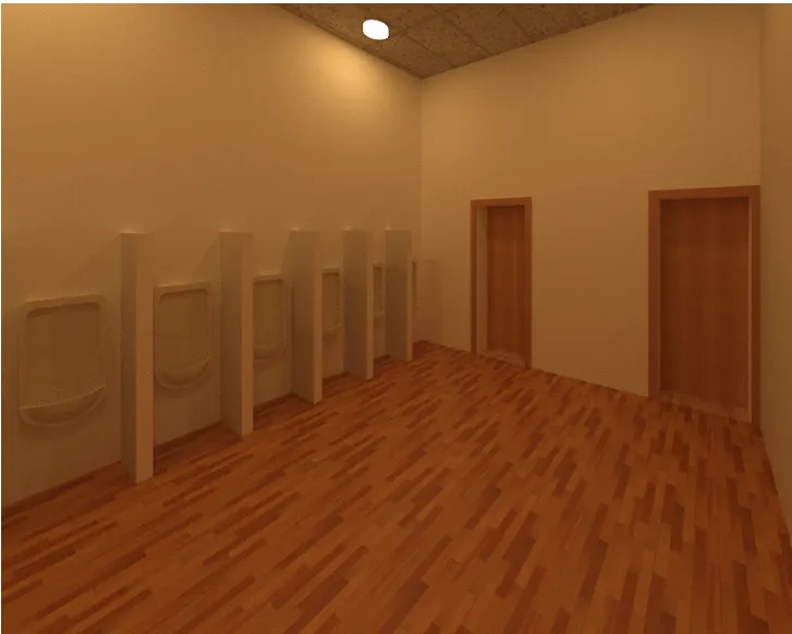
Restroom
- Select 'Sheet' in the 'View' tab
- Select 'A0 metric' and click 'OK'
- Change the contents in the sheet by double clicking the subject
- Drag the all the 1st to 4th Floor Rendered 3D images to the sheet from 'Project Browser' under 'Renderings'
- Adjust the image inside the sheet
- Select 'Text' in the 'Annotate' tab
- Type the necessary texts and place it in the sheet
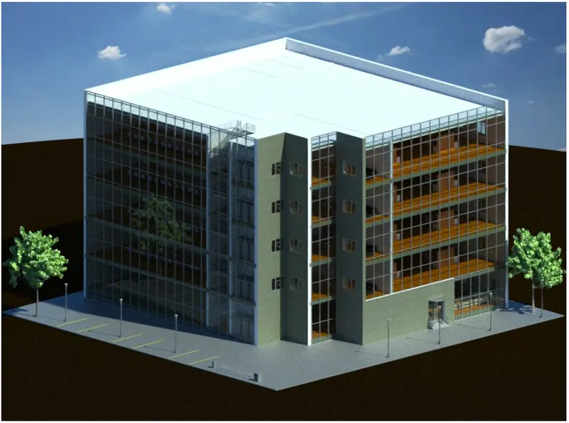
b. Rendering from out showing topographic features
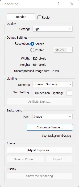
- Select '3D View' under the 'View' tab
- Click and drag the 'View Cube' to adjust the image
- Select 'Render' under the 'View' tab
- Set 'Quality - Setting: High'
- Set 'Lighting - Scheme: Exterior: Sun Only'
- Set 'Background - Style: Image'
- Click 'Adjust Exposure' under 'Image' and set accordingly
- Click 'Save to Project' under 'Image'
- Click 'Render'
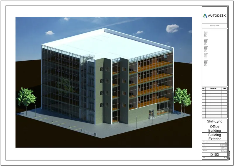
- Select 'Sheet' in the 'View' tab
- Select 'A0 metric' and click 'OK'
- Change the contents in the sheet by double clicking the subject
- Drag the Rendered 3D image showing topographgy to the sheet from 'Project Browser' under 'Renderings'
- Adjust the image inside the sheet
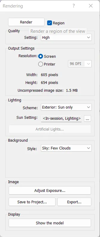
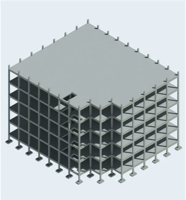
c. Rendering through structural framing
- Open existing 'Project Structure' file
- Select '3D View' under the 'View' tab
- Click and drag the 'View Cube' to adjust the image
- Select 'Render' under the 'View' tab
- Set 'Quality - Setting: High'
- Set 'Lighting - Scheme: Exterior: Sun Only'
- Set 'Background - Style: Sky: Few Clouds'
- Click 'Adjust Exposure' under 'Image' and set accordingly
- Click 'Save to Project' under 'Image'
- Click 'Render'
- Select 'Sheet' in the 'View' tab
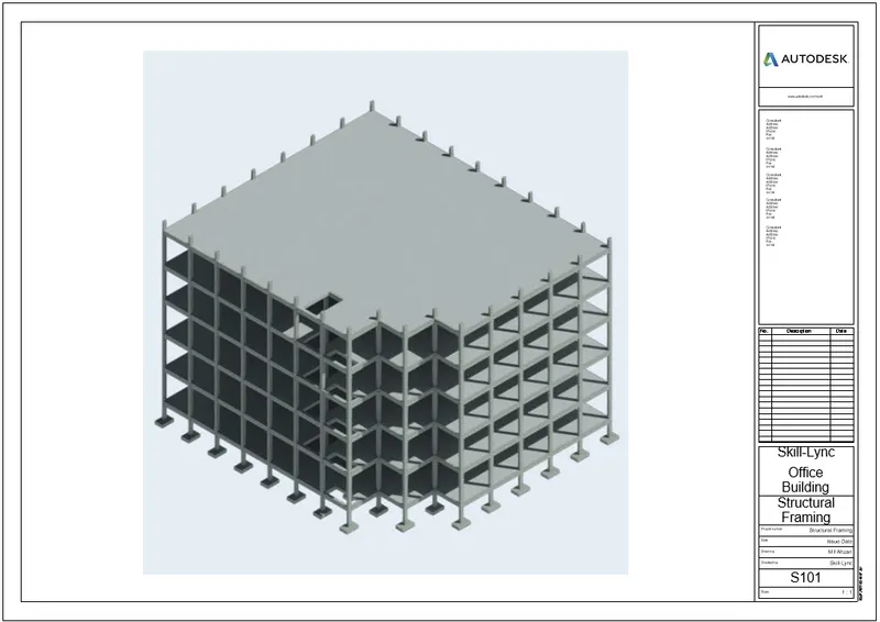
- Select 'A0 metric' and click 'OK'
- Change the contents in the sheet by double clicking the subject
- Drag the Rendered structural framing 3D image to the sheet from 'Project Browser' under 'Renderings'
- Adjust the image inside the sheet
STEP: 7
7. Print the set of drawing sheets created and submit the drawings from the architecture and structure model
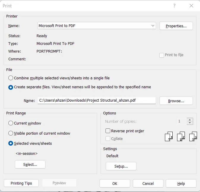
- Go to the sheet view, use 'ctrl+P' to open 'Print' dialogue box
- Use the below options as same for every print
- Click 'OK'
The final print of the sheet is given in the below results
RESULTS
The set of drawing sheets created is printed and the drawings from the architecture and structure model is submitted
A101: Ground Floor Plan
A102: 1st Floor - 4th Floor
B101: Elevations
C101: Sections
D101: Ground Floor Interior
D102: 1st - 4th Floor Interior
D103: Building Exterior
S101: Structural Framing