Creating Architectural and Structural model with 3D rendering using REVIT
ANSWER
AIM :-
To create a school building with proper location and geographic features , having every building components in it , provide different views in sheet , render the building , draw structural drawings as well and provide every thing which are mentioned in the question.
INTRODUCTION :-
Revit is a commercial building information modeling (BIM) software by the company Autodesk. It's generally used by architects, structural engineers, mechanical, electrical, and plumbing (MEP) engineers, designers, and contractors. Autodesk Revit allows users to create, edit, and review 3D models in exceptional detail.
PROCEDURE :-
Open the revit software
Then go on the front page by pressing cntrl + D
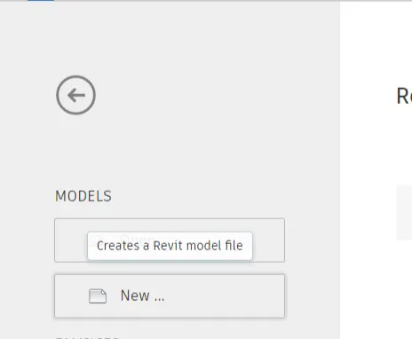
Select the new optio from there to start making the school building
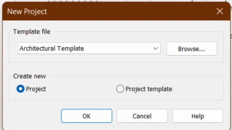
Then there open a new dialogue box in which select the architectural template and then click ok to proceed
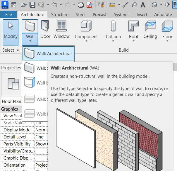
After that the Blank Page will open and then go to the architecture tab and click on the wall option to draw the walls of the building
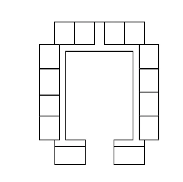
We have a signed the walls and created walls for our school building as per our designed requirements and taken care of the NBC requirements too
Now let us attach the doors to our building
For that go to the architecture tab where you will find the door option
Click on that option
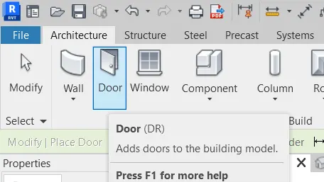
Then the Ribbon bar will be changed and then go to the load family option

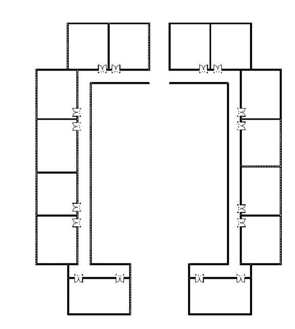
After loading the door from the load family option our building structure will look like this
Now to add the windows
Go to the architecture tab and then go to the windows option
Click on the windows option
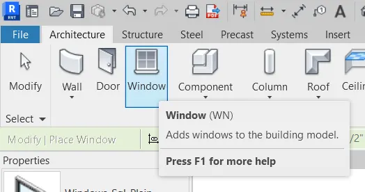
The Ribbon bar will be changed and hence click on the load family option again
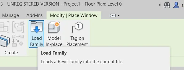
Now select the type of Window or door you want to attach in the building and then click ok
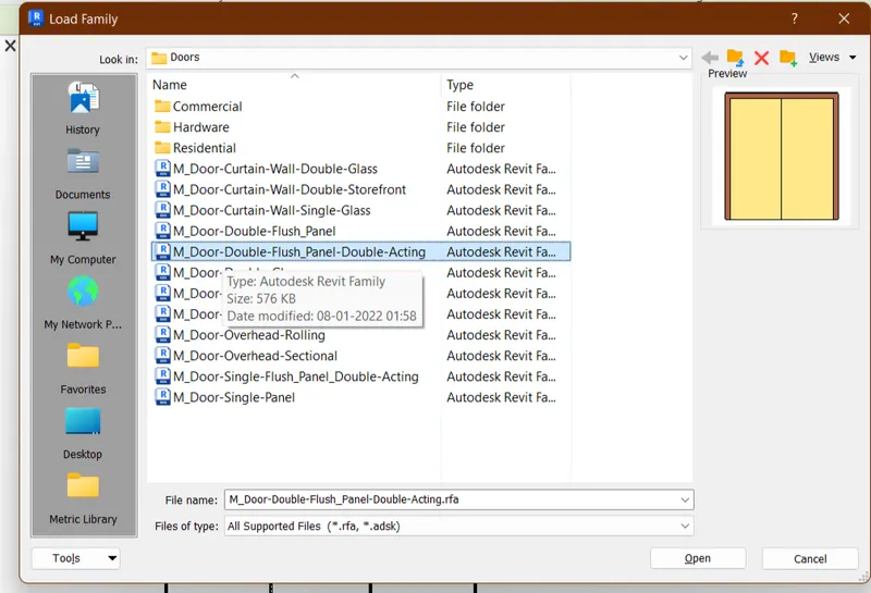
Hence our doors and windows components are being attached in our school building
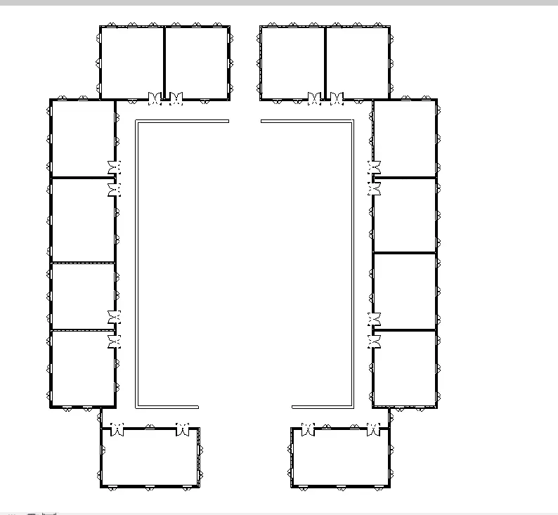
Now it's time to construct the floors of our building
For that go to the architecture tab again where you will find the floor option
Click on architecture floor option
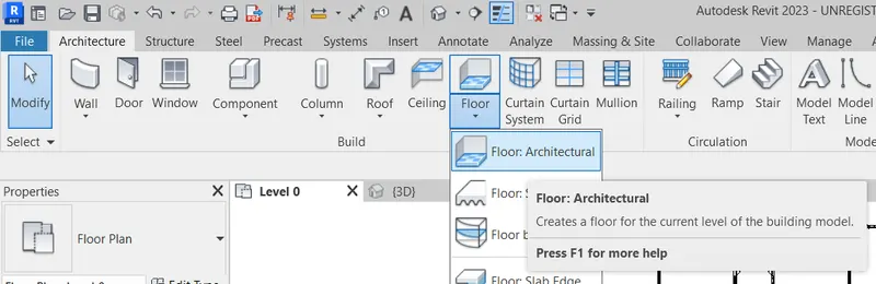
Ribbon bar will be changed and then there will be options click on the pick line or pick wall option to create the floors

After that click on finish to complete the floor construction
Go to the 3D view to view the floor that has been created
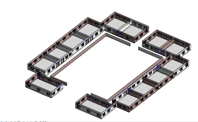
Now to make the first floor and second floor and roof level
Select the building which we have created
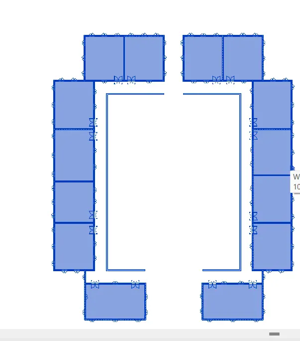
Then there occur a modify tab
Click on the copy to clipboard option

Then click on the option and select the aligned to selected levels option
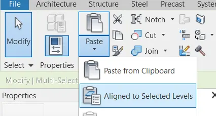
Hence our building has been created as a multi story school building as per our required number of floors
Now to construct the columns in our building
Go to the architecture tab again where you will find the column option
Click on architectural column
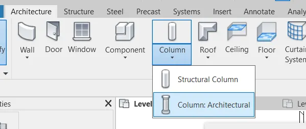
And then provide the colum as per the requirements wherever is required
And then provide the columns wherever required in the building
For the construction of the roof level
Go to the architecture tab where you will find the roof option
Click on the roof option and the Ribbon bar will be changed
Select the building part where you want to create the roofs.
And then click on finish

Hence you can see that roof has been created in our building
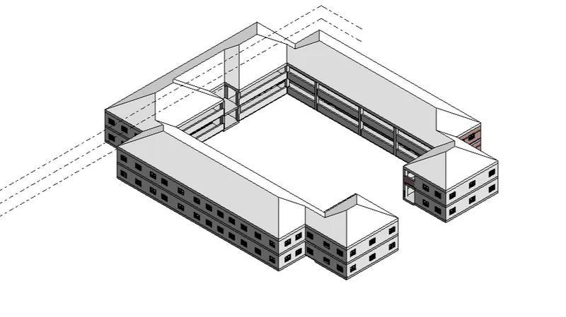
Now to make it as a flat roof
Select the roof
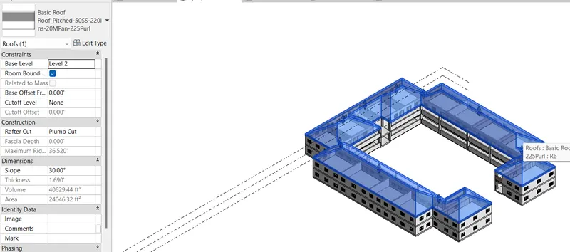
Then go to the property Browser
Where we will find the slope option
Put it as zero to make it a flat roof
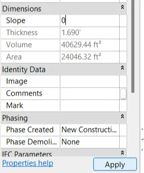
Hence flat roof has been created
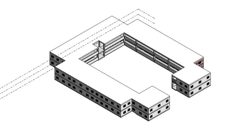
Now to add the railing in our roof level
Go to the architecture tab where will find the railing option
Click on that and then draw the railing as per the requirement
Hence railings has been created our building roof
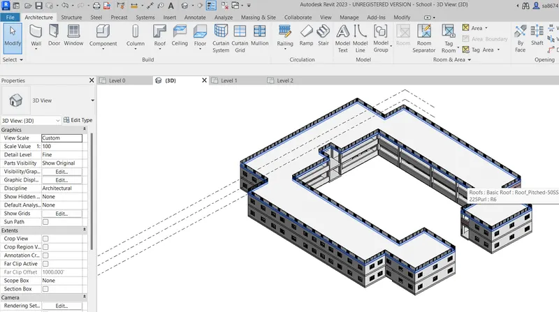
Now to add the components in our building
Go to architecture tab and then go to the component option
Select the place a component option
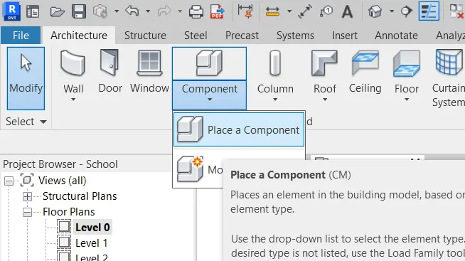
Go to the load family option in the Ribbon tab

And then load the components that are required to be placed in the building
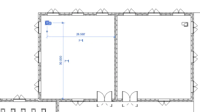
As I have placed a chair
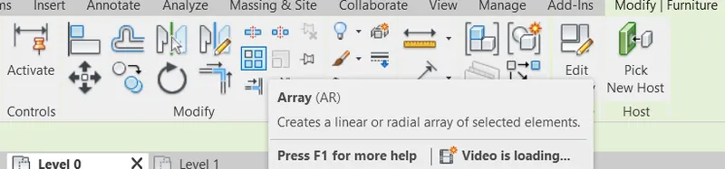
So to array the chair, select to the chair and then the Ribbon tab will be changed
Then go to the array option
And select the pic point for that chair
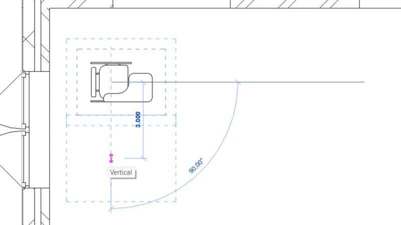
Hence provide the number of quantities you want and place them in a proper direction
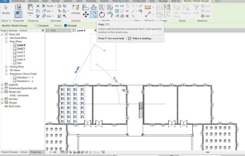
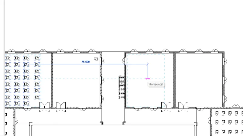
Now to copy the place the components in the different levels
Select the components which you have placed
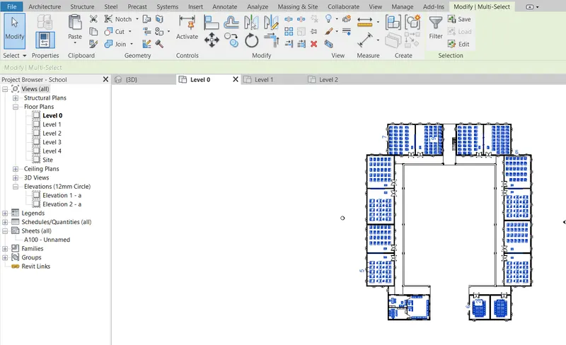
Then go to the copy to clipboard option
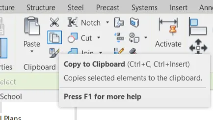
After that go to the paste option and then select the aligned to selected levels option
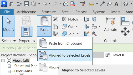
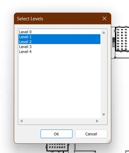
There will open a dialogue box
Select the levels where you want to place the components
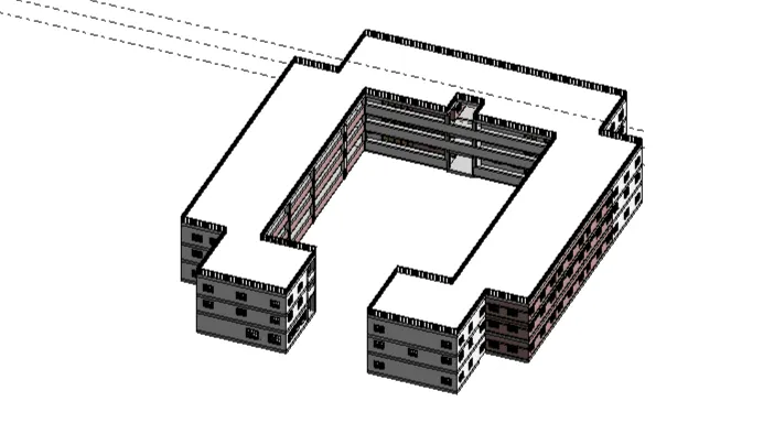
And this is a 3D view of our building with all the components placed in it and with different levels
Now to add the topo surface
Go to the massing and site option where you will find a topo surface tool
Click on that tool and then draw the surface as per your requirement

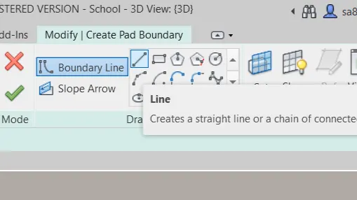
Also to add the building pad for our building
Go to the same massing and site option
Click on building pad option
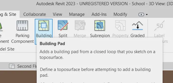
Now choose a method to draw the building pad for your building
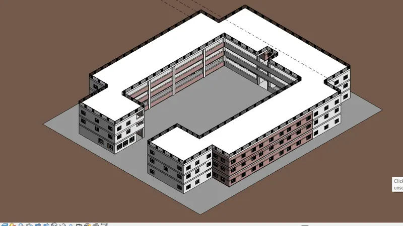
Now we see the building pad and topo surface of our building
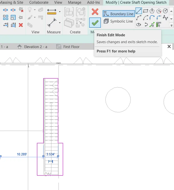
Now to create the opening for the staircase
Go to the architecture tab

Then go to the modify toolbar and then select the shaft option from there
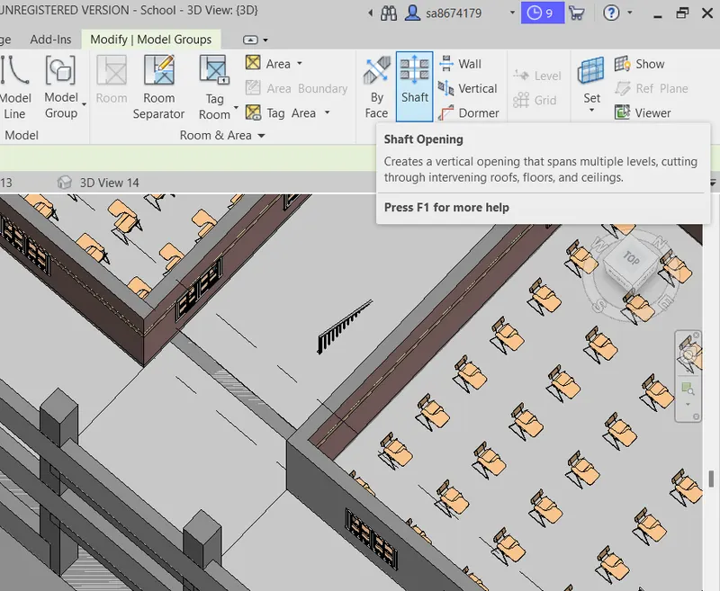
Provide the shaft where you want to provide the stair in the building
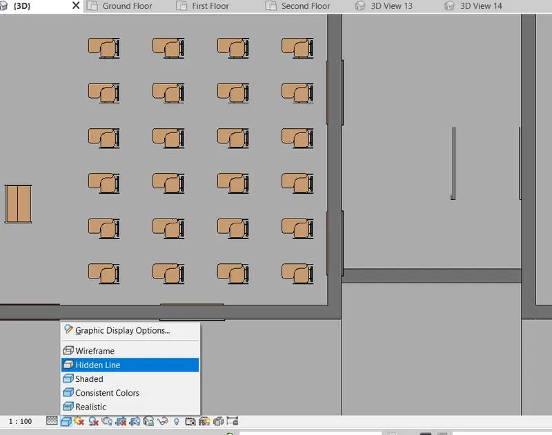
To see the shaft opening vimarsh change the view to wire frame
and then do the required adjustments
Now to create the stair go to the architecture tab and then go to the stair option and place the stair where you want

Also to create the ceiling of our building
Go to the architecture tab
Click on the ceiling option
Then click on the sketch ceiling option
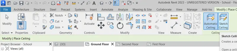
After that a Ribbon bar will be changed and then select the appropriate type to draw the ceiling and then click on finish
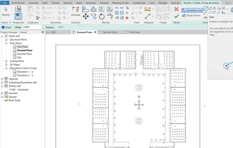
As the components of our building earlier
Now to provide the opening for the different components for the detailing perspective
Go to the component where you want to create the opening
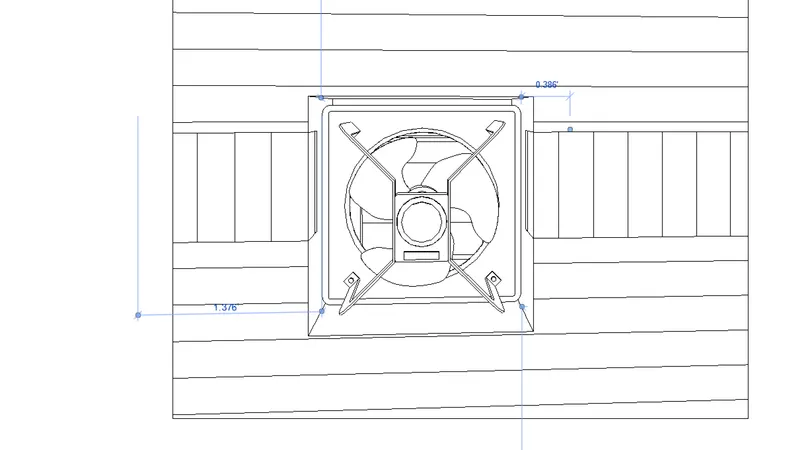
Select the wall and then select the wall opening option
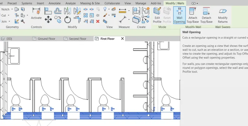
Now you can see the wall openings which have been created in the washroom for the exhaust fan
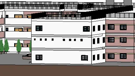
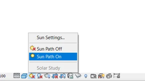
Now to turn on the sun path feature
It is available in the bottom tab
Just click on the Sun path on option
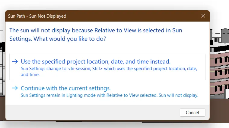
Then this dialogue box will open where you can select the required setting
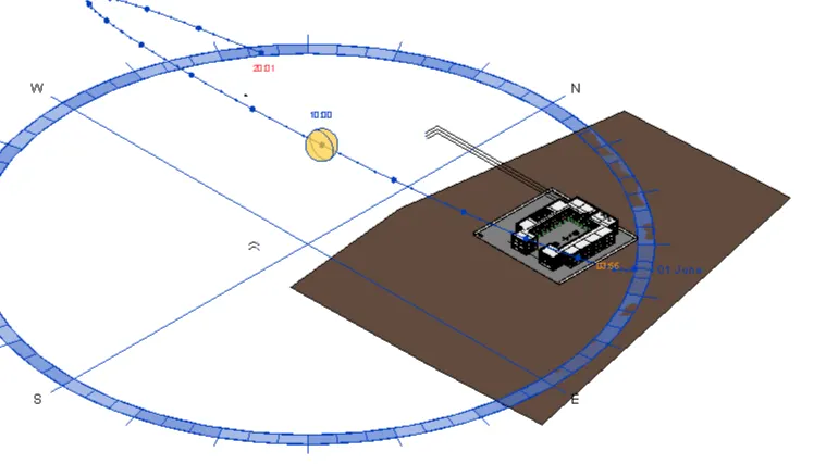
And hence now you can see that the Sun path has been created and you can adjust it as per your requirements
After that now to create the grids for our building for the structural plan
Go to the architecture tab where you will find the grid option

After clicking on the grid option there the Ribbon bar will be changed and then select the required appropriate type to draw the grid lines

Hence horizontal grid lines have been created
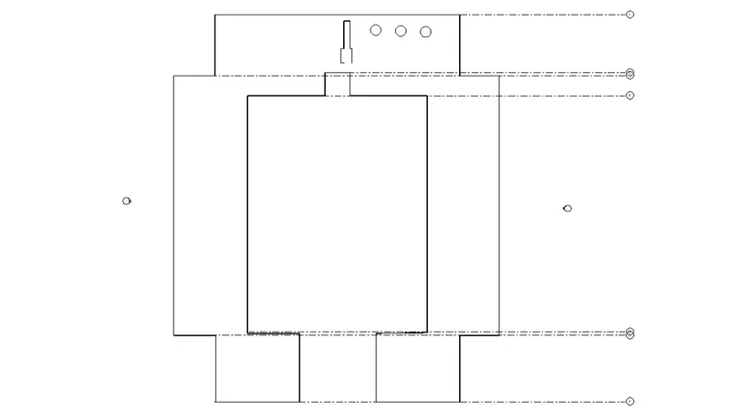
Similarly draw the vertical grid lines for the school building
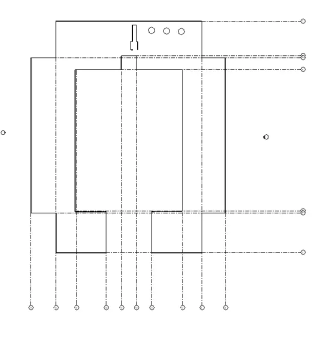
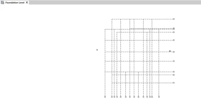
Now you can see the grid lines in the foundation level as you have created it for the structural plan
Now to add the footing in our structural model
Go to the structure tab and then click on the isolated structural footing option
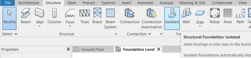
Then go to the at grids option to draw the foundation at the provided grids

After that select the grids and click on the finish option to place the footing
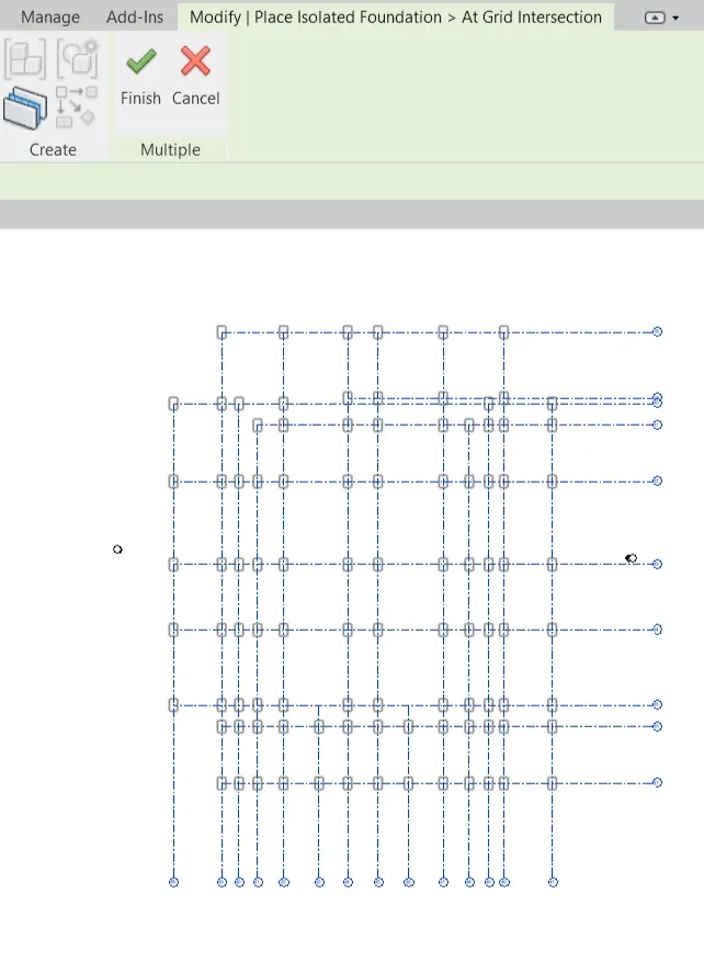
Hence isolated Foundation has been created in our structural model
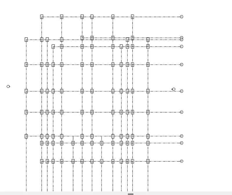
Now to add the columns in our building
Go to structure tab and then go to the column option
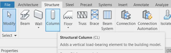
Select the type of column you want and then click on the at grids option
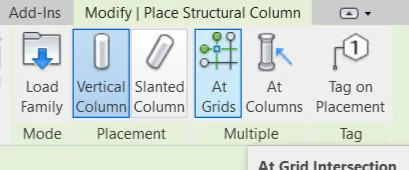
After that select the grids and click on the finish option to save the changes
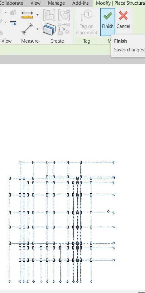
Hence here you can see the 3D view of our building with isolated Foundation and the structural columns
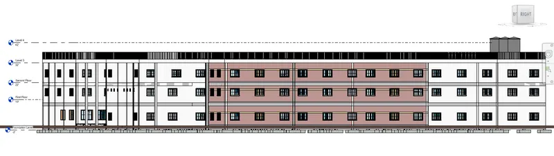
Now to add the beams in our structural model
Again go to the structure tab and click on the beam option
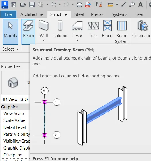
Then click on the on grids option and select the structure
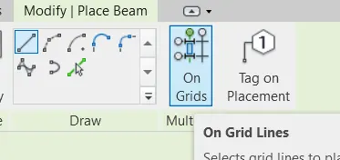
After that click on the finish option to finish the construction of beams in the model
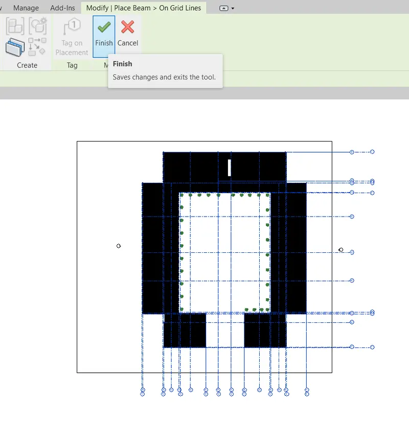
Hence this is the 3D view of building with isolated footing and columns and the beams created in it
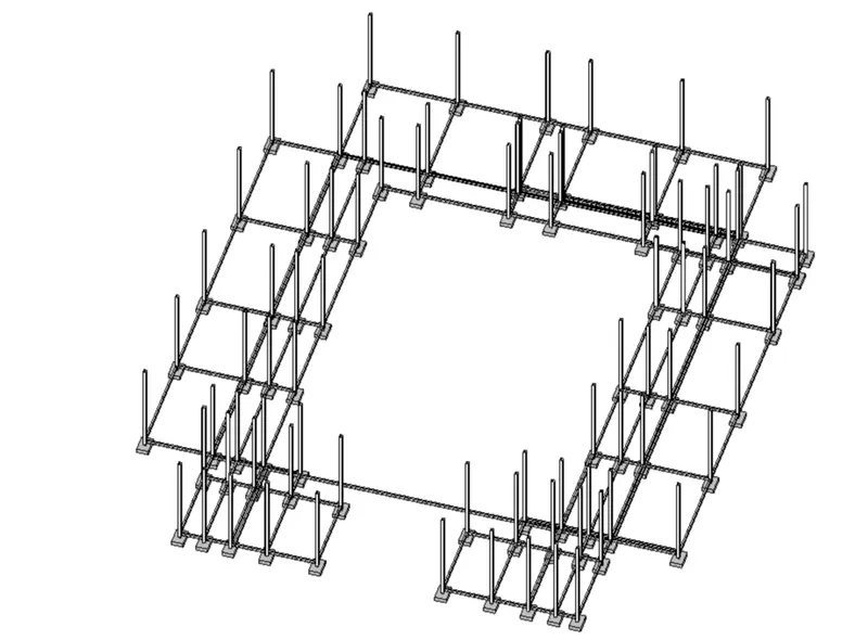
Follow the same step for every level and then after creating it in different levels our structural model will look like this
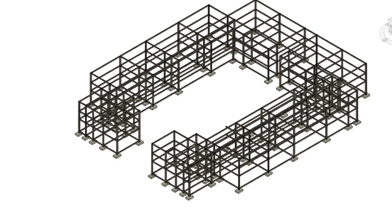
Now to add the floor in our structural model
Go to the structure tab and click on the floor option
Select the structural floor
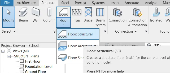
Then select the building where you want to create the floors with the help of the Ribbon tab and appropriate option to create the floor
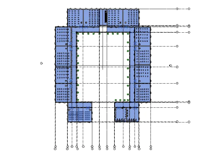
Hence floors have been created in our different levels of our model
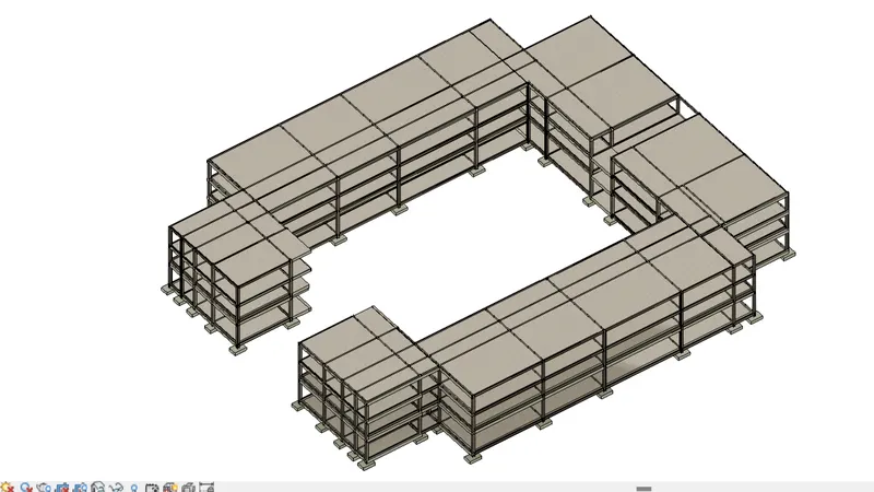
Now to provide the shaft opening for the staircase
Go to the modify tab where you find the shaft option
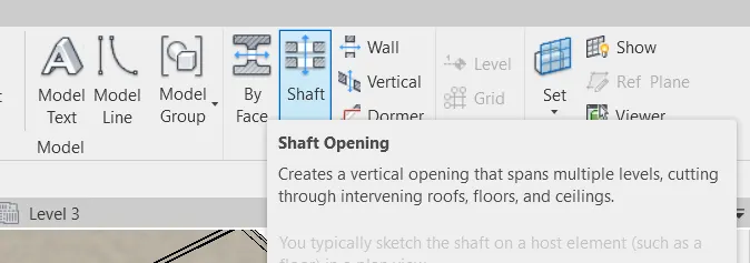
Click on that and then select the line option to draw the lines for the opening of the staircase as per the requirement and then click on the finish to create the opening
To create sheets for different views
Go to the view tab and then click on the sheet option which is available there
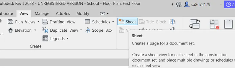
After clicking on the sheet option there opens a new dialogue box in which select the type of sheet views you want to create or load it from the family option also
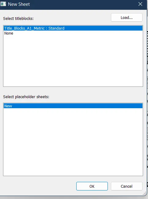
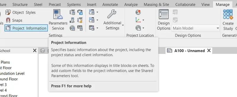
After that to edit the information that are to be mentioned in the project.
Go to the manage tab where you will find up project information option and then click on that
After clicking on that a dialogue box will open in which feed the required data which you want to enter
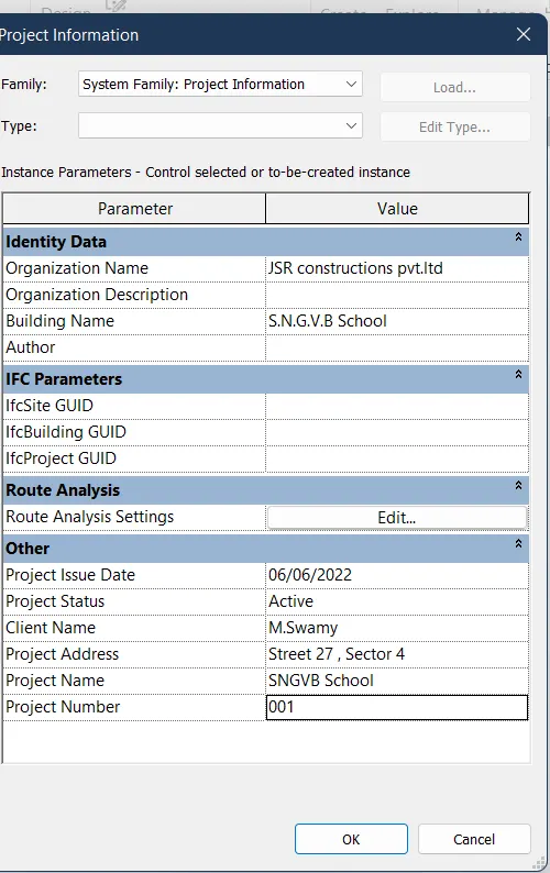
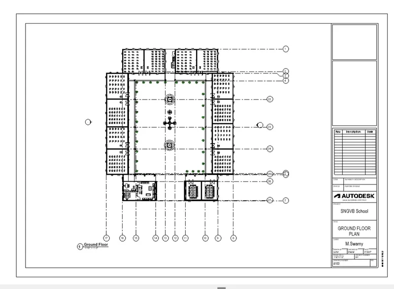
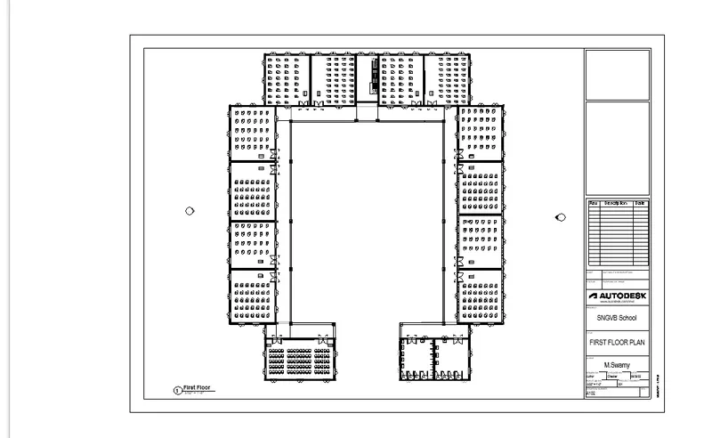
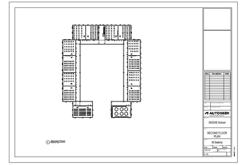
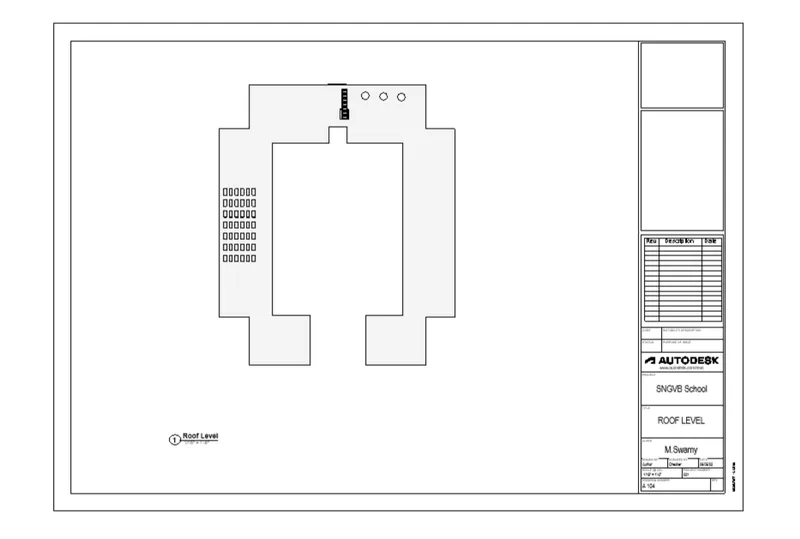
After that different sheets have been attached as per mentioned in the question
a. Ground floor plan
b. First floor plan
c. Second floor plan
d. Roof level plan
e. Structural Foundation level plan
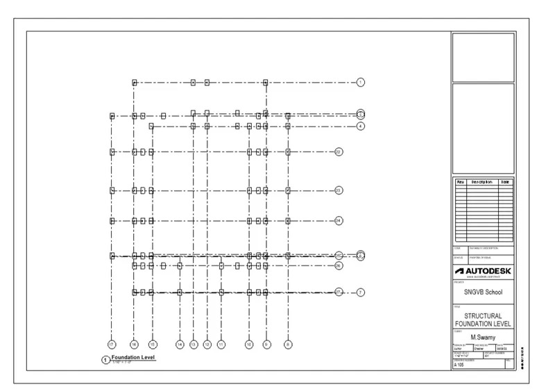
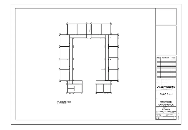
f. Structural ground floor plan
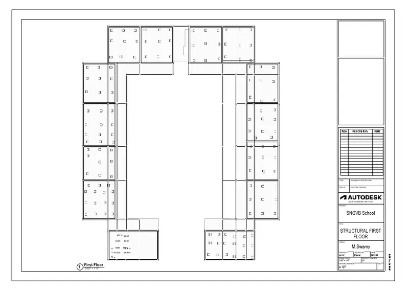
g. Structural first floor plan
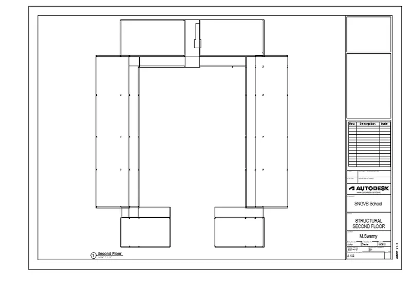
h. Structural second floor plan
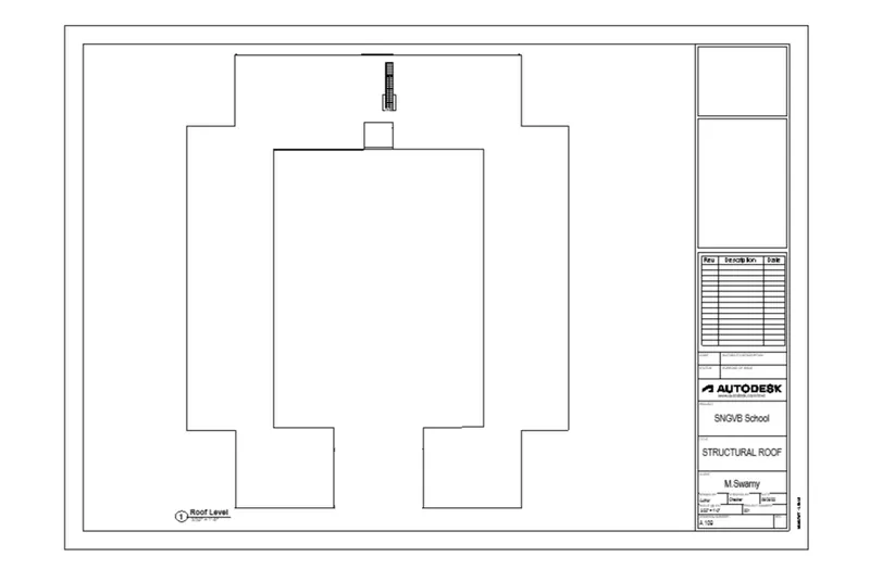
i. Structural roof plan
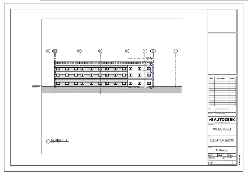
j. Elevation plan (west)
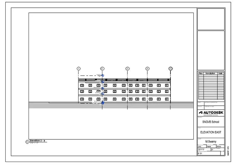
k. Elevation plan (east)
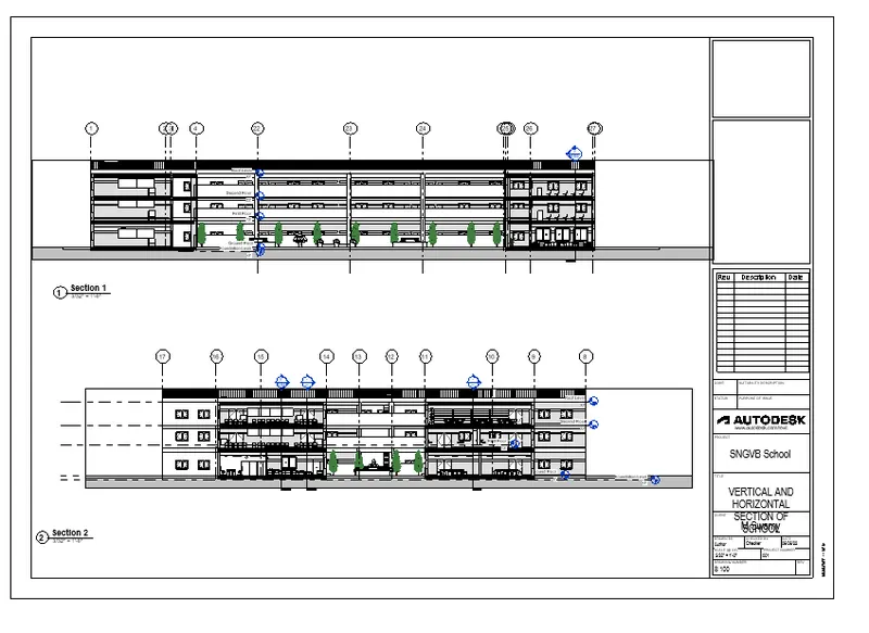
SECTION PLAN
l. Vertical and horizontal section of the school
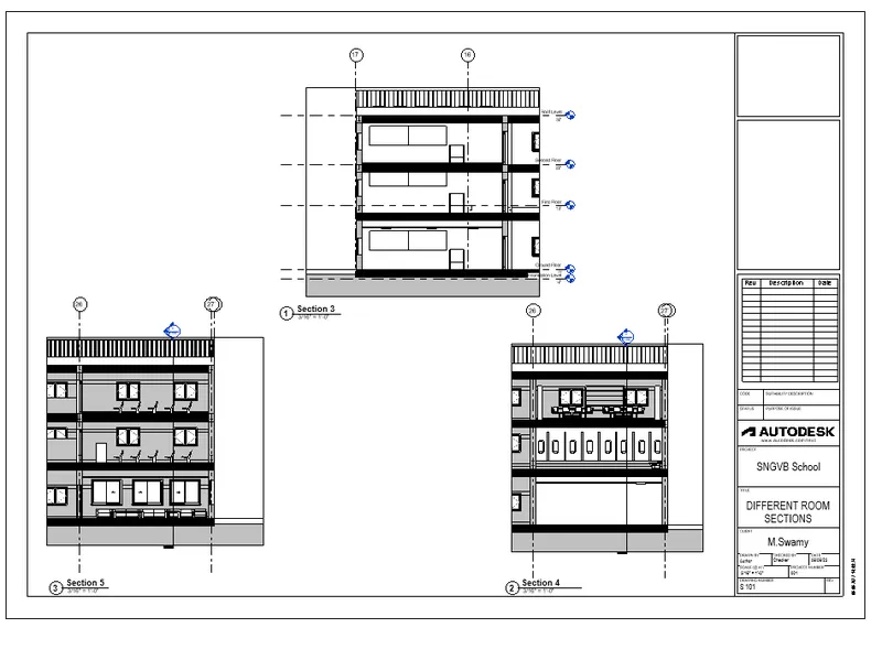
m. Different sections of different rooms
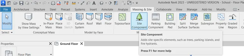
After that to add the site components in the building that is trees plants etc
Go to the masing and site option and then click on the site component
At the required component which you want and place them in the model
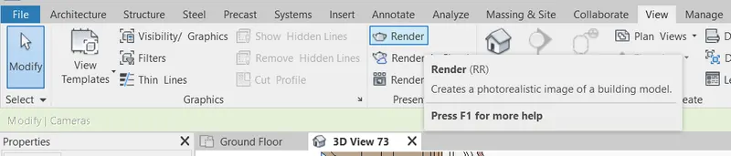
RENDERING :-
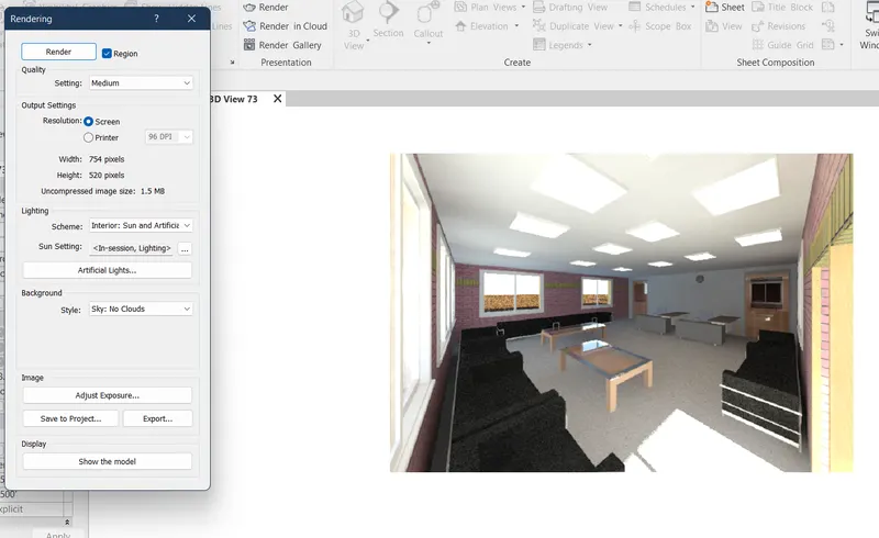
Now to render the created views of different rooms of our building
Go to the view tab where you will find the render option
Click on that
A dialogue box will open
Select the required setting which you want to give
And then start rendering
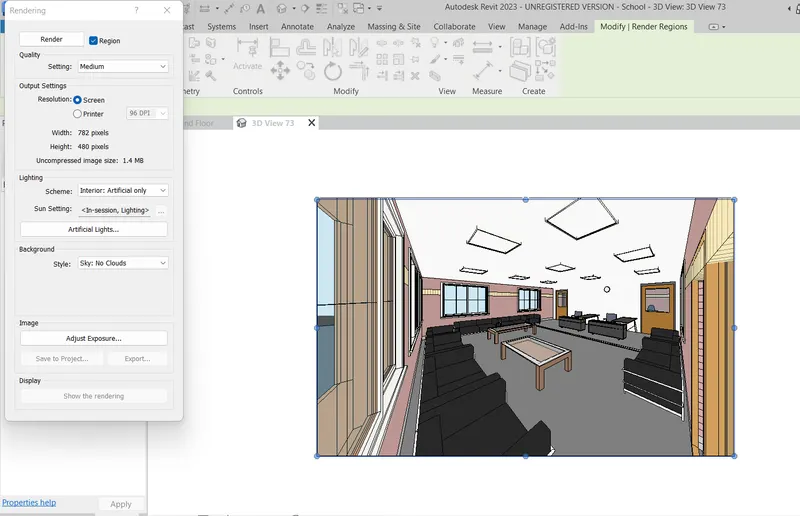
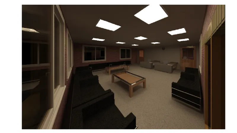
This is the rendered image of the office room or reception room of our school building
The same image has also been rendered in the presence of Sunlight and internal lights
And the result is been attached below
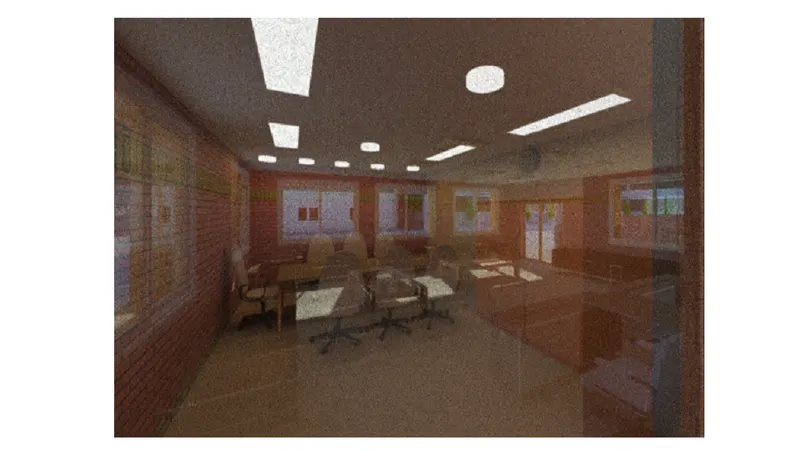
c.RENDERERED IMAGE OF ADMINISTRATION ROOM ;-
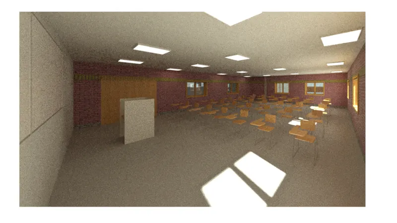
D.RENDERED IMAGE OF CLASSROOM
E.RENDERED IMAGE OF PRACTICAL ROOMS
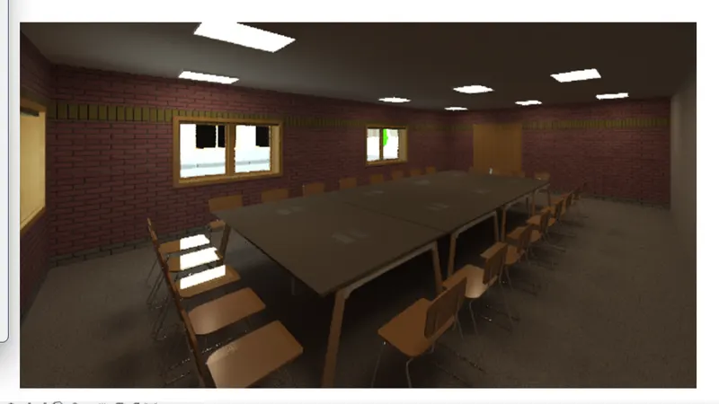
f. RENDERED IMAGE OF LIBRARY
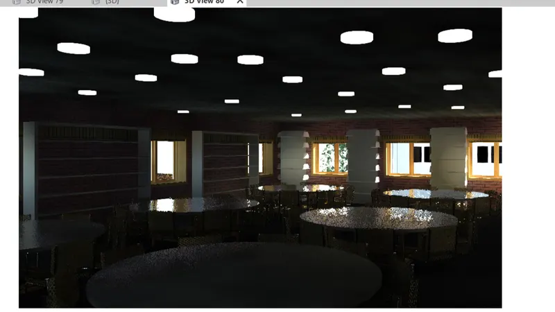
g. RENDERED IMAGE OF ROOF
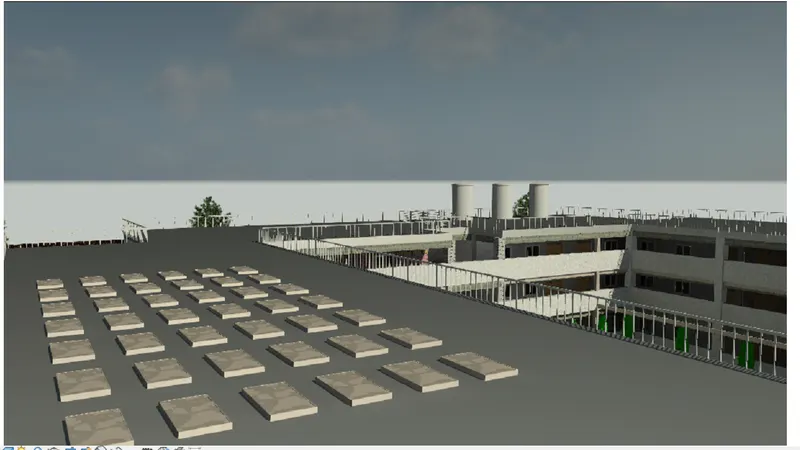
h.RENDERED IMAGE OF HOME VIEW OF SCHOOL
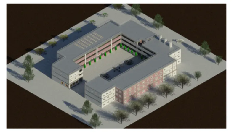
i.RENDERED IMAGE OF FRONT VIEW OF SCHOOL
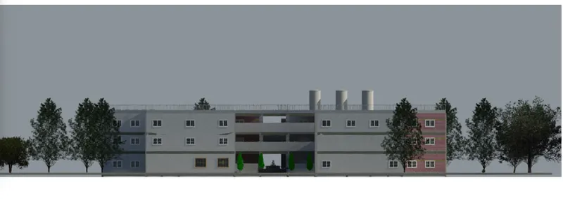
j. RENDERED IMAGE OF MID TOP LEVEL OF SCHOOL
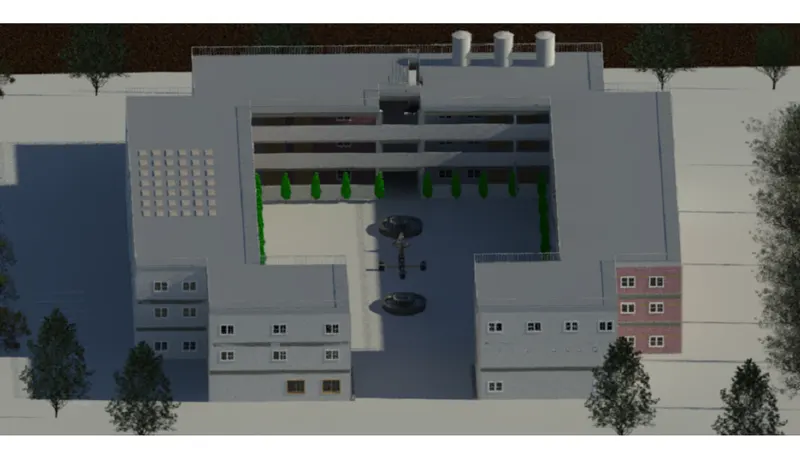
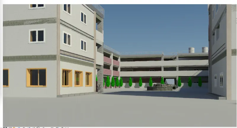
k.RENDERED IMAGE OF OPEN AREA INSIDE SCHOOL
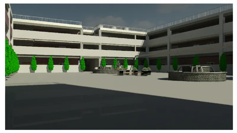
l. RENDERED IMAGE OF CORRIDOR VIEW
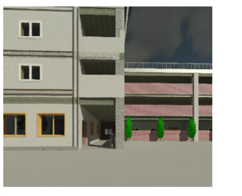
m. RENDERED IMAGE OF SCHOOL ENTERANCE VIEW
PRINT :-
Now to print the created model
Go to the print option which is available on the top of the toolbar or else just press cntrl + p to go to the printing option
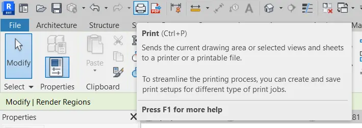
Then there will open new dialogue box in which select the required settings which you want to provide for your project
It also can be saved as a pdf or can be print.
RESULT :-
Hence the project of creating School has been completed and the every detailing which are mentioned to be provided in the model project has also been provided with the help of the revit software.