Creating Architectural and Structural model with 3D rendering using REVIT
AIM-1: Select the type of structure you want to build from one of the three below:
a. Multi-Unit Residential Apartment
b. Office Buildings
c. School
ANS: OFFICE BUILDING.
AIM-2: Assume reasonable assumptions for geographic and location details for your project modeling. Based on assumptions and type of structure selected identify the modeling requirements from NBC
PROCEDURE:
- i choosen buiding office building its comes under the commersial constractio
- area is 60000sqfts in that buitup area is 30000 sqft as per NBC
- It is commersial building so provide multiple exits for safety as per NBC
- set backs are taken as 15' as required mention in NBC
- Width of road abutting the building taken as 100' a per commersial usage for parking and vegitation.
AIM-3: Using the structural model, include the following components based on the type of structure selected
a. Foundation – Isolated / Wall/Matt Foundation
b. Columns
c. Beams Connected to Columns
d. Roof Framing/ Truss
e. Floor / Decks
f. Floor Openings for Elevators and Stairs
INTRADUCTION:Construction Revit technicians use computer modeling software to create technical drawings and three-dimensional building designs. They work closely with architects and engineers to develop plans for clients. Revit technicians need to have excellent artistic, technical, and computer skills
PROCEDURE:
STEP-1:
- open the revit application we get welcome page appear select new icon their
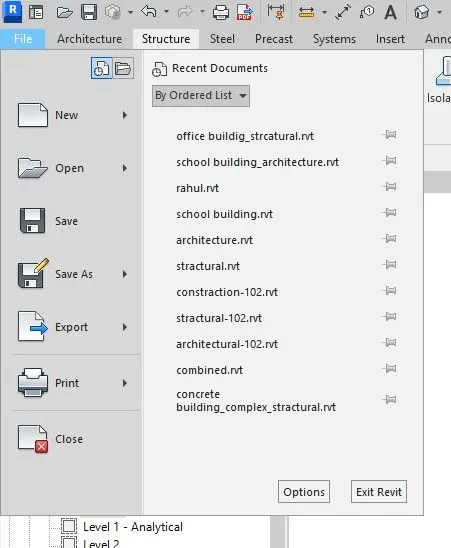
- save that file from file tab
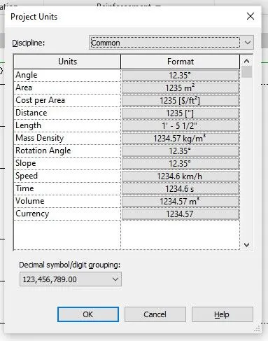
- after that set units for click "un" we get pop-up window appear set distance units as feets and inches and length units as feet and fractional inches.
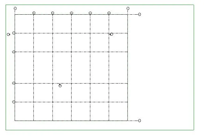
- select grid from sractural tabplace in the working screen by width of 30'

- now set a levels go to project browcer select any elevation east west any and set levels
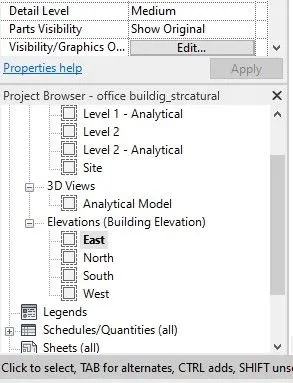
- now select the level icon from a stractural tab

- set levels with the height of 12' as per NBC
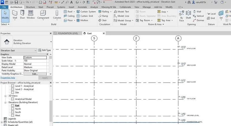
- now all set to the place footings and constraction elements.
STEP-2:
- Now go to project browcer selct footing level plan then go starctural tab and select isolated footing

- then we get editing tools appeared related isolated footing select at grids icon we get another tab appeared then drag right click on the working screen to select all the grids
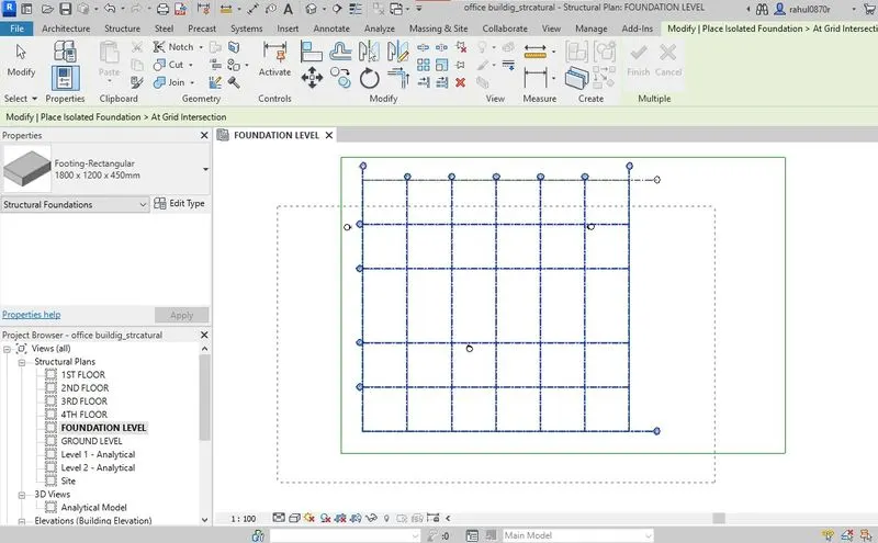
- after that footing are placed in the junction points of grids click tikmark on the appear in tool tab.

- now comes columns slect from stracture tab then change column type from properties browcer to rectanguler column
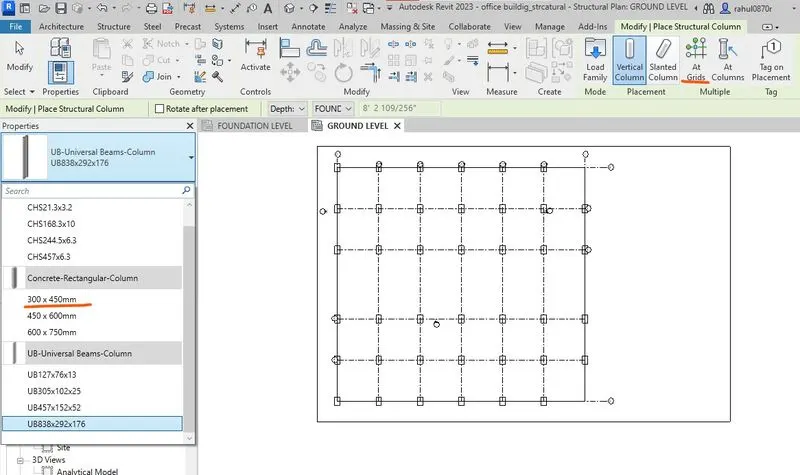
- then select at the grids in the edit tools tab then drag to select all the grids columns are place in junction of the point
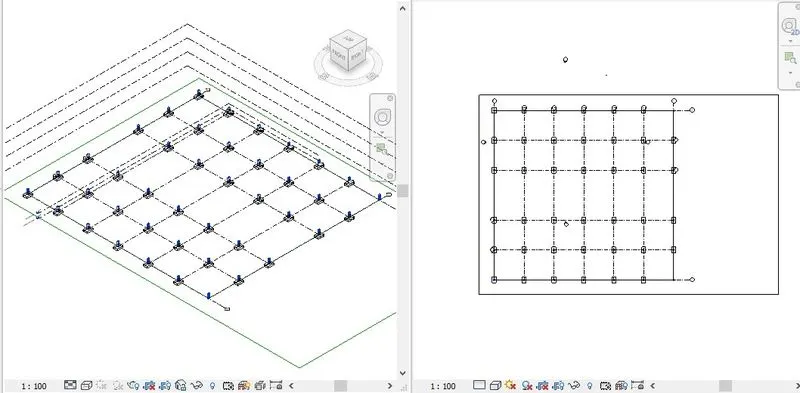
- now select the all the columns change height of the column till roof from properties browcer
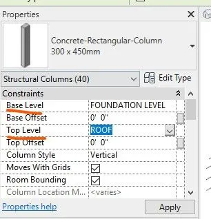
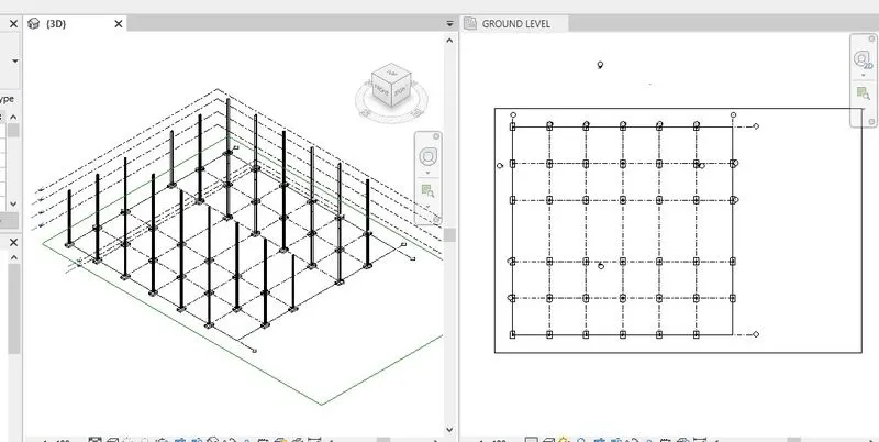
- now columns reach to roof level
- now place beams select from stractural tab
- select rectanguler beams in propeties browcer then select at the grids in edit tools tab.
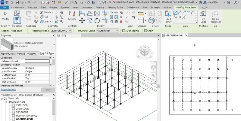
- then select the all the grids by drag are seperatly
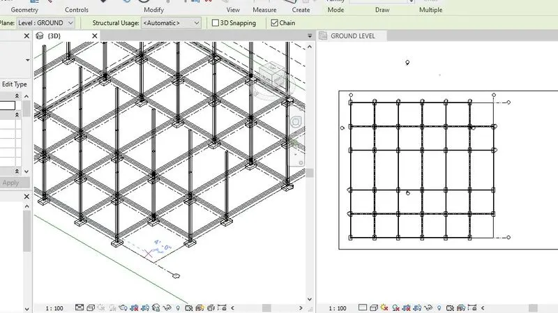
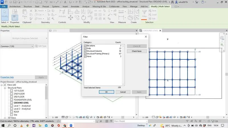
- now select the all elements in the working space then we get fillter tool appear in the tab in ribbion
- remove tik marks exacept stracture frameing click ok
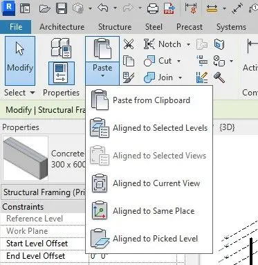
- then all the beams are selected then go to the copy tool in editing tool tab after paste icon is enable then select the paste buttion select rolling options related of aligned to selected levels
- we another dailog box appeared releated floor levels availabile
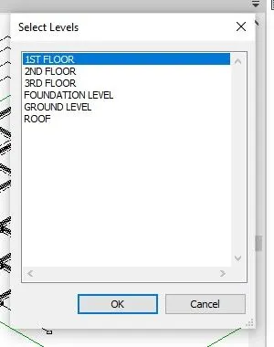
- select the required levels where to paste the beams then click ok require level beams are placed till 3rd floor
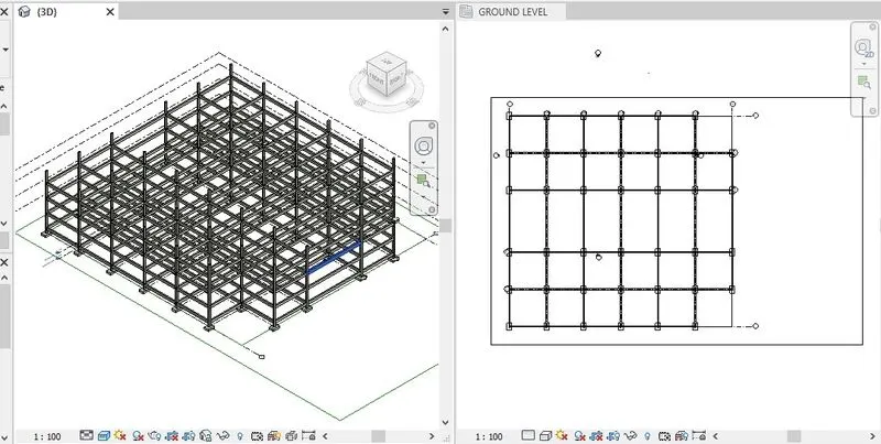
- then select floor in the stracture tab after that select line option from editing tools tab then draw the floor line in reqired region
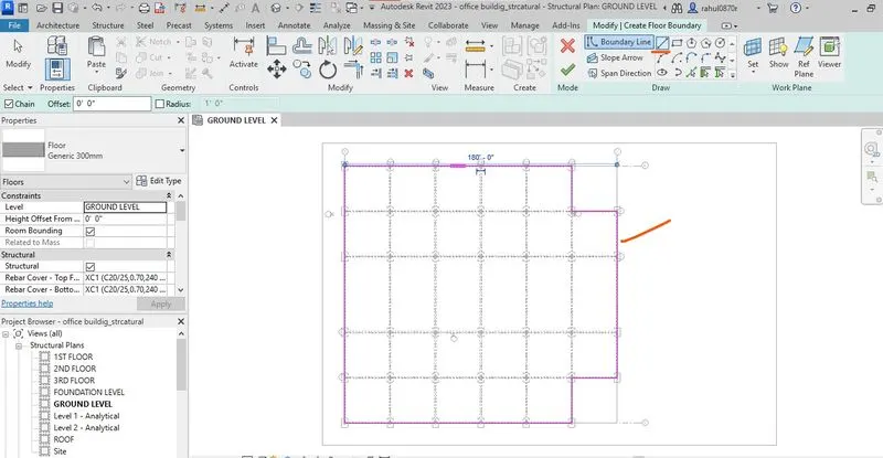
- click right mark to floor is created.
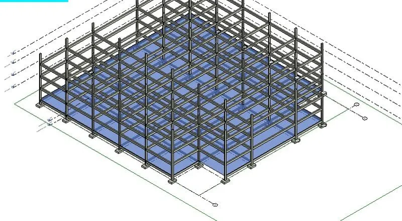
- then select the floor select option from editing tools tab then select the paste command then select the in which floor to paste.
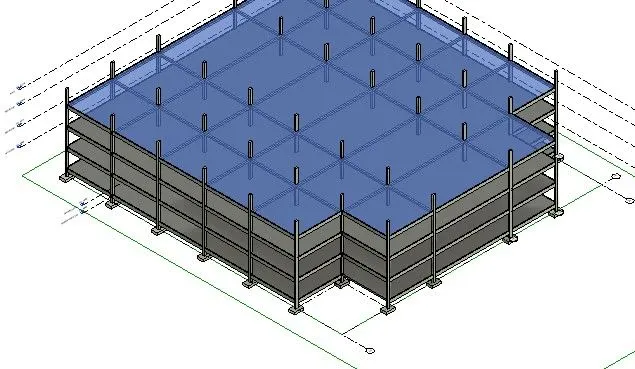
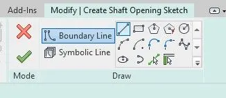
- now create shaft opening for stairs and lift purpose.
- select shaft from stracture tab in tools.

- now modify tools appeared select rectangle from that and draw the rec in slab area where we are placeing stairs and lift designed
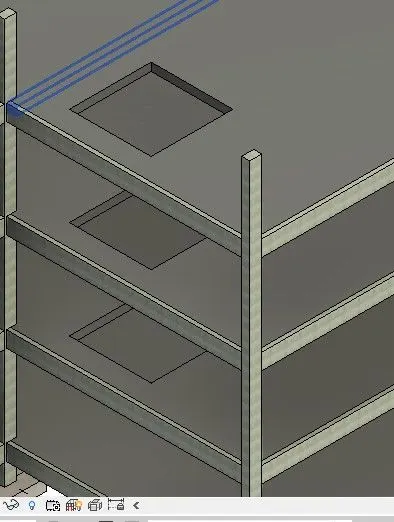
RESULTS: ALL THE ELEMENTS ARE CREATED AS MENTION IN AIM IN BELOW
a. Foundation – Isolated / Wall/Matt Foundation
b. Columns
c. Beams Connected to Columns
d. Roof Framing/ Truss
e. Floor / Decks
f. Floor Openings for Elevators and Stairs
AIM-4: Using the architectural model, include the following components based on the type of structure selected
a. Wall Layout with appropriate material and finishing
b. Exterior façade with fancy finish
c. Interior partition walls to size rooms
d. Components to add details to a room ( Desk, Chair, Lighting, Plumbing fixtures)
e. Add components such as stairs Elevators
f. Have at-least one side of the building with curtain walls and glass panels
g. Include interior and exterior lighting fixtures
h. Place proper topographic components from outside ( Trees, Parking, Plants) to add details to the model
INTRADUCTION:Construction Revit technicians use computer modeling software to create technical drawings and three-dimensional building designs. They work closely with architects and engineers to develop plans for clients. Revit technicians need to have excellent artistic, technical, and computer skills
PROCEDURE:
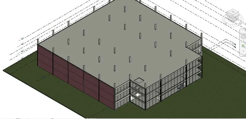
- Continous to previous now select the wall from a architecture tab and front wall consider as glazed wall like glass
- now added interior walls placed with room seperated
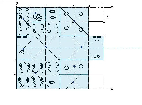
- now added components through the arecitecture tab select components.
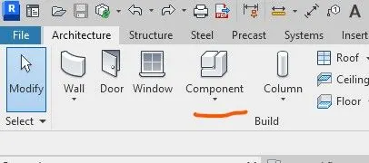
- then we get another design tools tab appear then select load family

- then we get the components revit library files appear then select require component
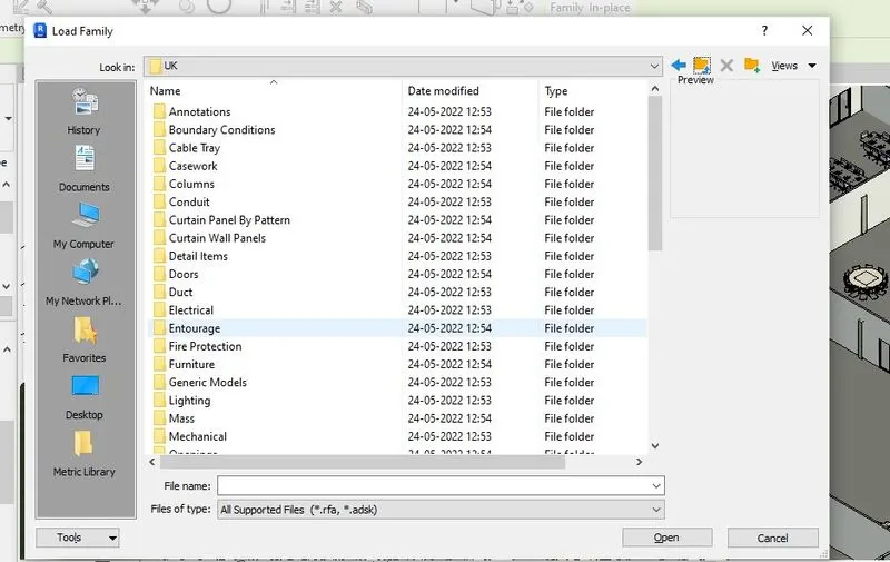
- select require components then place in to require field
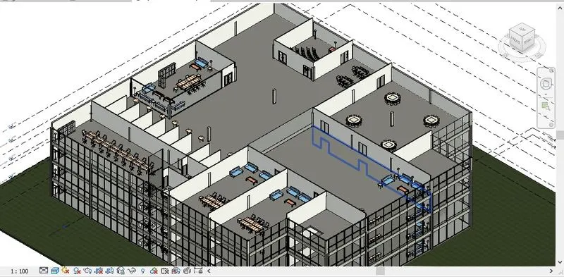
- then select components and interior walls then paste that components till 3 floors.
- then select the stairs icon from architecture tab then place in require field
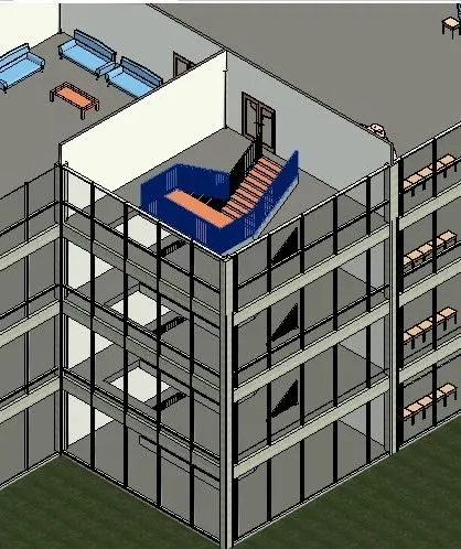
RESULTS:
AS MENTION AIM ELEMENTS COMPLETED
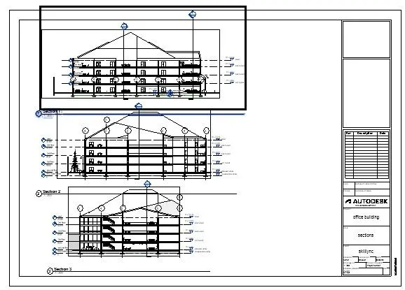
AIM-5: Provide a set of drawings in an architectural and structural model to list the following details with categories and appropriate sheet templates included
a. Floor Plans with Annotations
b. Elevations
c. Sections
PROCEDURE:
- Now go to view tab and slect files icon
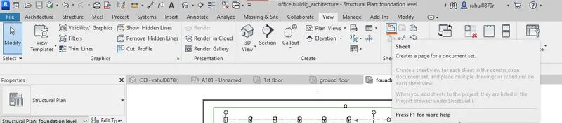
- then we get a dailog box appeared
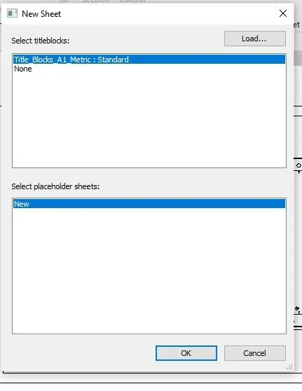
- then click ok that template appeared revit working window then select require field change name in the template
- then draw reqire field and place in template
RESULTS:
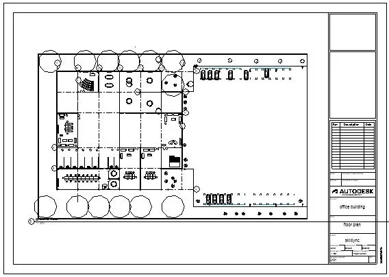
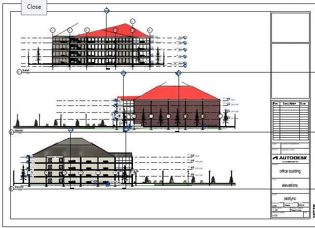
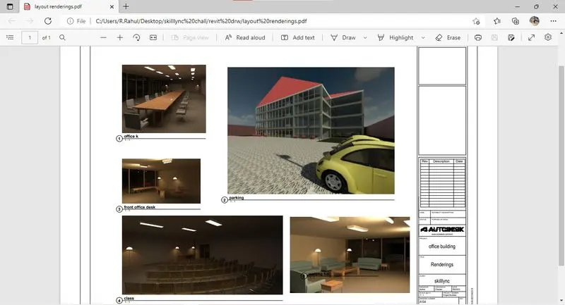
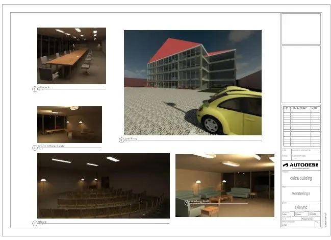
AIM-6: Using the Rendering settings, Render images of the 3D model produced and include the rendered images to the drawing sheets
a. Rendering from interior rooms
b. Rendering from out showing topographic features
c. Rendering through structural framing
PROCEDURE:
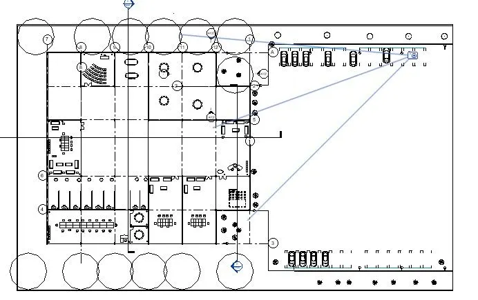
- Select cemera place in require place then select that cemera face enter
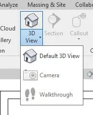
- place cemera inrequire places
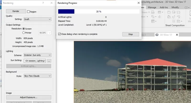
- then we get view go to view tab select render icon we get a dailog box
- we can select the render quality,brightness,sun light or artificial light and clouds quantity.
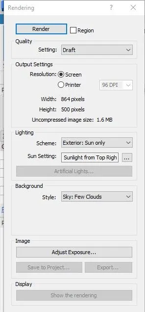
- change require elements then click on the render icon process started
RESULTS:
AIM-7 :Print the set of drawing sheets created and submit the drawings from the architecture and structure model
PROCEDURE:
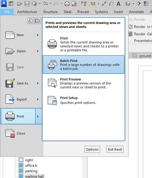
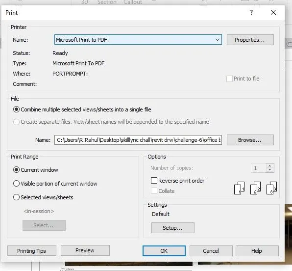
- Go to file menu< slect print < now click on the preview< or direct press print<we page setup option< select microsoft to print< click ok< it downloaded.
RESULTS: