Creating Architectural and Structural model with 3D rendering using REVIT
1) Select the type of structure you want to build from one of the three below:
a. Multi-Unit Residential Apartment
b. Office Buildings
c. School
Ans: In this project I am going to build an office building
It comes under Group E : Business Buildings according to NBC
This type of buildings are constructed for carrying out business related activities. The main purpose of such buildings is to carry out business transactions, keeping of important records and accounts etc. It includes city halls, dispensaries, clinics, libraries, office buildings etc.
2) Assume reasonable assumptions for geographic and location details for your project modeling. Based on assumptions and type of structure selected identify the modeling requirements from NBC
The plinth or any part of a building or outhouse shall be so located with respect to average road level from site so that adequate drainage of the site is assured but at a not height less than 45 cm
The maximum height of building shall not exceed 1.5 times the width of road abutting plus the front open spaces.
If a building abuts on two or more streets of different width, the building shall be deemed to face upon the street that has the greater width and the height of the building shall be regulated by the width of that street. Height shall however, not exceed the maximum height as provided in the Master Plan.
a)Every building meant for human occupancy shall be provided with exits sufficient to permit safe escape of occupants in case of fire or other emergency.
b) In every building exit shall comply with the minimum requirement of this part, except those not accessible for general public use.
c) All exists shall be free of obstructions.
d) No buildings shall be altered so as to reduce the number, width or portion of exits to less than required.
e) Exits shall be clearly visible and the routes to reach exits shall be clearly marked and signs posted to guide the occupants of floor concerned.
f) All exit ways shall be properly illuminated.
g) Fire fighting equipment where provided along exits shall be suitably located and clearly marked but must not obstruct the exit way and there should be clear indication about its location from either side of the exit way.
h) Alarm devices shall be installed to ensure prompt evacuation of the occupants concerned through the exits, wherever required.
i) All exits shall provide continuous means of egress to the exterior of a building or to an exterior open space leading to a street.
j) Exits shall be so arranged that they may be reached without passing through another occupied unit, except in the case of residential building
The minimum area for office room/shop or any other space to be used as workspace shall not
be less than 6.0 sq m. with a minimum width of 2.1 m.
My project is in plain area
Area is commercial
Road width infront of the office building is 70 ft
3) Using the structural model, include the following components based on the type of structure selected
a. Foundation – Isolated / Wall/Matt Foundation
b. Columns
c. Beams Connected to Columns
d. Roof Framing/ Truss
e. Floor / Decks
f. Floor Openings for Elevators and Stairs
Introduction:
Structural Model Elements are, literally, elements that support a structure such as columns, rebar, trusses, and so on. This section discusses how to manipulate these elements.
Column and Beams
Structural column, beam, and brace elements do not have a specific class such as the StructuralColumn class but they are in the FamilyInstance class form.Though the StructuralColumn, StructuralBeam, and StructuralBrace classes do not exist in the current API, they are used in this chapter to indicate the FamilyInstance objects corresponding to structural columns, beams, and braces.Though Structural column, beam, and brace are all FamilyInstance objects in the API, they are distinguished by the StructuralType property.
Stairs
A Stair is a series of steps with or without landings or platforms, which is installed between two or more floors of a building to bridge a large vertical distance”.
Procedure:
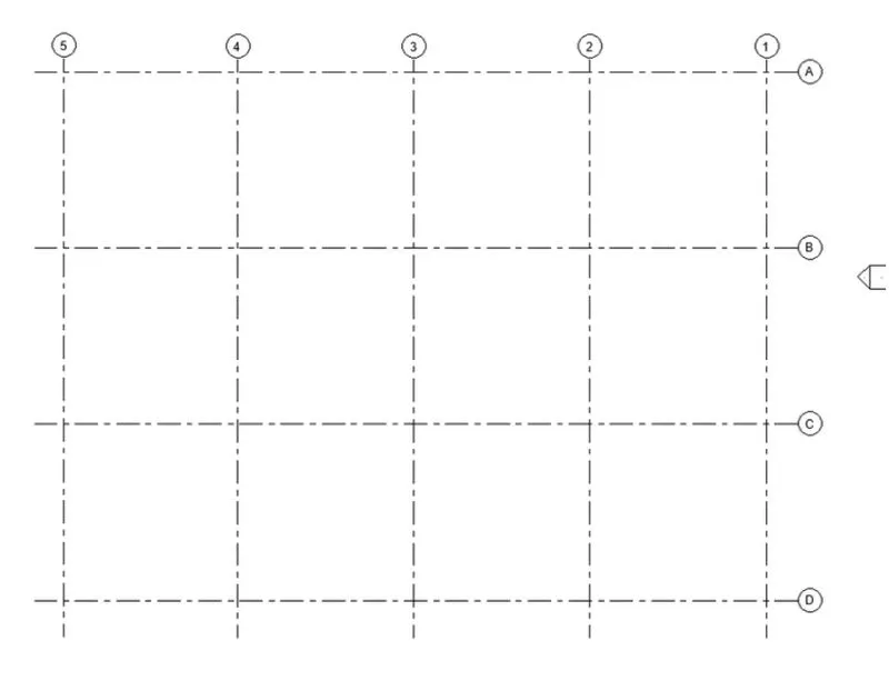
1) Open REVIT and make horizontal and vertical grids at spacing of 30' as per NBC
2) Grids are annotation elements that help organize your design.
- On the ribbon, click Grid
- Architecture tab>Datum panel>Grid
- Structure tab>Datum panel>Grid
- Click Modify | Place Grid tabDraw panel and select sketch option.
Use Pick Lines to snap the grid to an existing line, such as a wall.
- Click when the grid is the correct length.
3) Increase the number of levels upto roof and rename them as ground level, founadtion , first floor, second floor, third floor and roof
4) In addition to creating a level for each story in a building, you can also create reference levels, such as sill level.
- Open the section or elevation view to add levels to.
- On the ribbon, click >Level
- Architecture tab>Datum panel>Level
- Structure tab>Datum panel > Level
- Place the cursor in the drawing area and click.
5) As we place the cursor to create a level, if the cursor aligns to an existing level line, a temporary vertical dimension displays between the cursor and that level line.
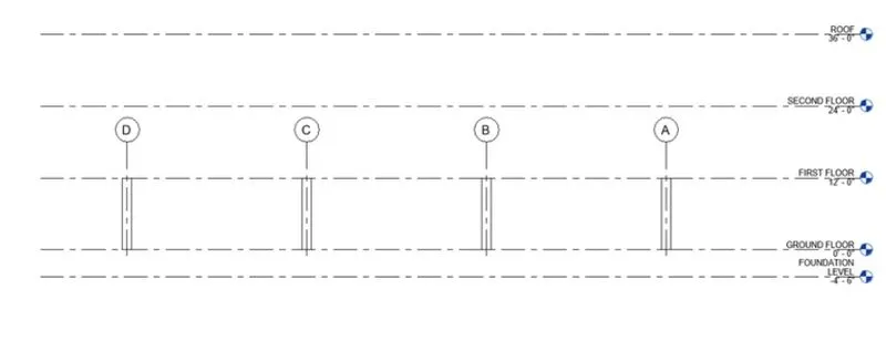
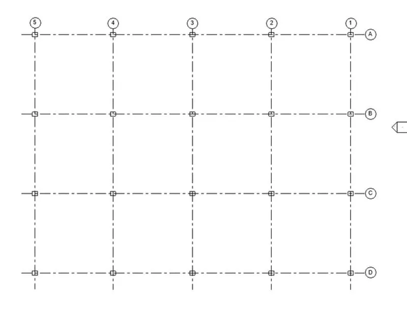
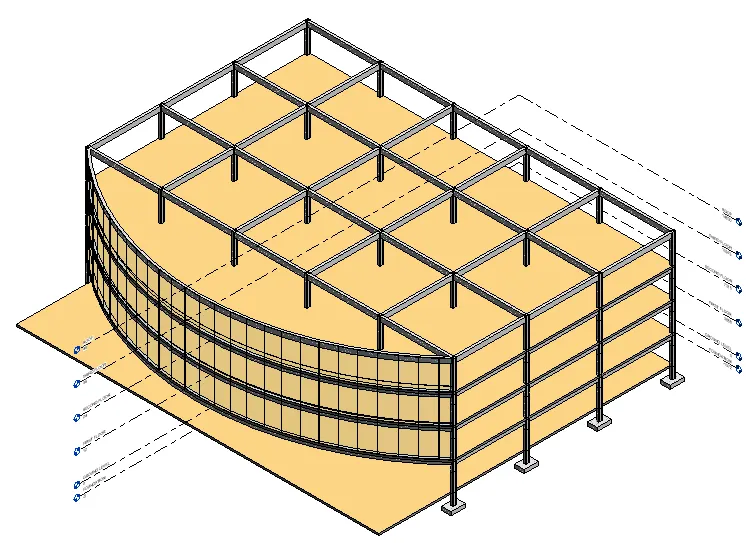
6) Select column from ribbon and place the columns at intersection of grids as shown
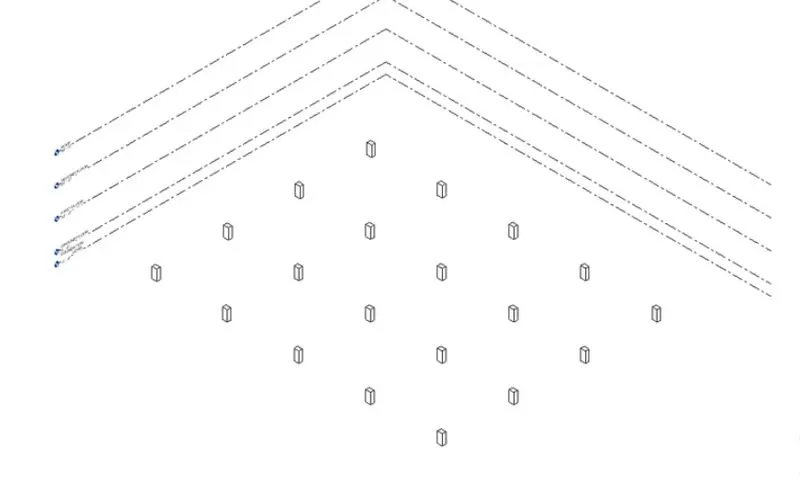
7) To publish from Revit, the model view should be the Default 3D View or a 2D Floor Plan. Use the House icon in the Quick Access Toolbar to quickly switch to the Default 3D View.Change the view to default 3d view to get an interface as shown below.
8) Place another column on the grid intersection from ground floor to first floor
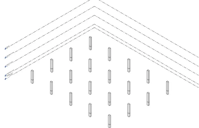
9) Select beam from the ribbon and connect this beam to different columns as shown
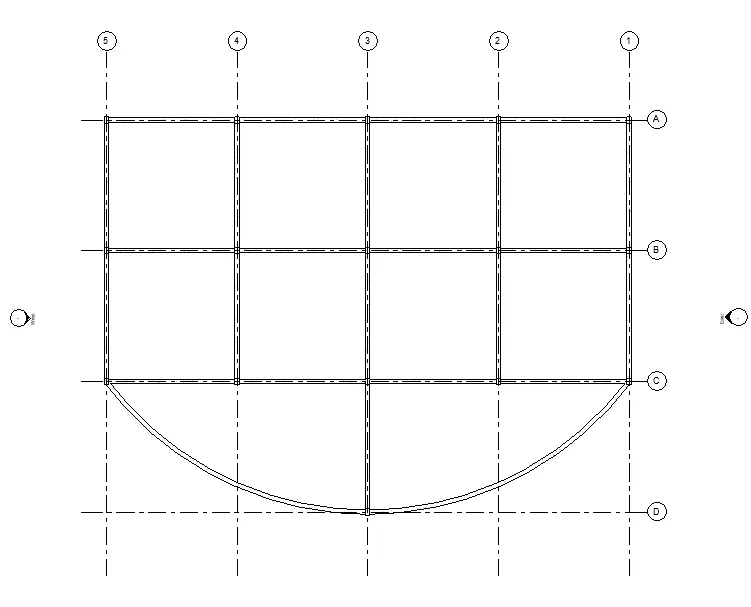
Change the view to 3d
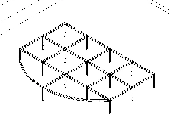
10) Go to the isolated option from the ribbon and place them on the different columns as shown
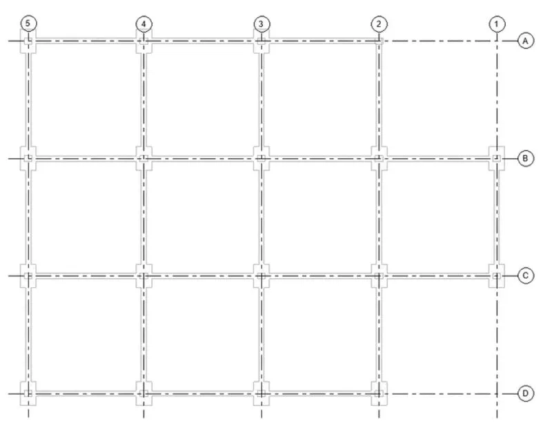
Change the view to 3d
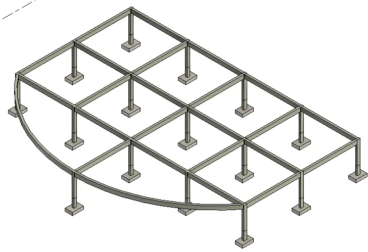
11) Select entire figure and go to the copy option and assign them to the first floor , second floor and third floor
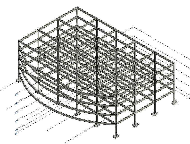
12) Now go to the ceiling option and change the view to ground floor and select points and make a loop and assign them to first, second, third floor
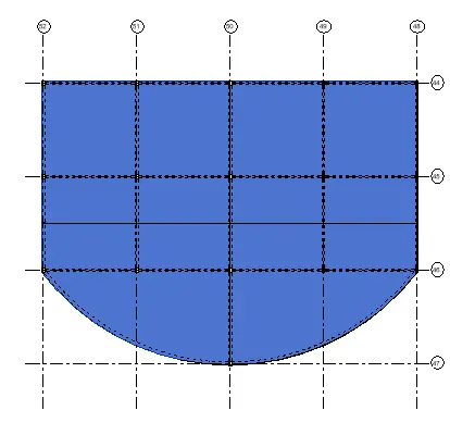
13) Select the ground floor and copy it to the assigned levels ie first floor , second floor and third floor
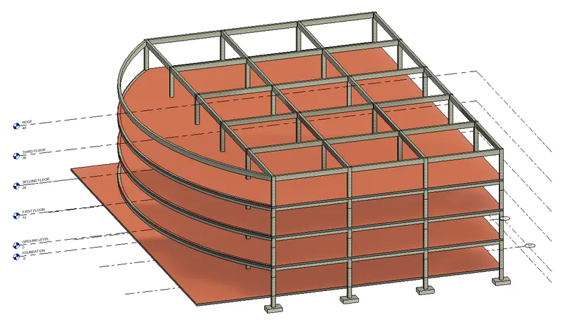
15) Change the front wall to curtain wall- external glazing wall
16) Roof option creates a roof using the building footprint to define its boundaries.
- Display a floor plan view or a reflected ceiling plan view.
- Click Architecture tab>Build panel>Roof drop-down>Roof by Footprint
If we try to add a roof on the lowest level, a dialog prompts you to move it to a higher level. If we choose not to move the roof to a different level, Revit notifies you later if the roof is too low.
- On the Draw panel, select a sketch or pick tool. To edit roof properties before sketching, use the Properties palette.
- Sketch, or pick, a closed loop for the roof.
- Specify slope defining lines. To change the slope definition of a line, select the line and, on the Properties palette, click Defines Roof Slope. We can then change the slope value.
- Click Finish Edit Mode, and then open a 3D view
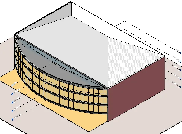
- Go to roof option and make a boundary and choose the material and angle to give a final touch to the roof
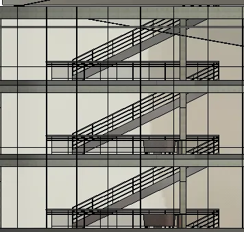
17) Go to the stairs option and choose any stair design , here we choose straight . Now select the base level as ground floor and upper constraint as first floor place the stair anywhere as per needed. Copy it to assigned levels ie first floor , second floor and third floor and roof . Now in the drawing plan create a shaft from ground floor to roof level where the lobbies serve as landing for the stairs
RESULT:
All the following components on the structure selected are inserted
4) Using the architectural model, include the following components based on the type of structure selected
a. Wall Layout with appropriate material and finishing
b. Exterior façade with fancy finish
c. Interior partition walls to size rooms
d. Components to add details to a room ( Desk, Chair, Lighting, Plumbing fixtures)
e. Add components such as stairs Elevators
f. Have at-least one side of the building with curtain walls and glass panels
g. Include interior and exterior lighting fixtures
h. Place proper topographic components from outside ( Trees, Parking, Plants) to add details to the model
INTRODUCTION:
An architectural model is a type of scale model – a physical representation of a structure – built to study aspects of an architectural design or to communicate design ideas. Depending on the purpose, models can be made from a variety of materials, including blocks, paper, and wood, and at a variety of scales.
Architectural models are used by architects for a range of purposes:
- Ad hoc models, or sketch models, are sometimes made to study the interaction of volumes, different viewpoints, or concepts during the design process. They may also be useful in explaining a complicated or unusual design to builders, or as a focus for discussion between designers and consultants such as architects, engineers and town planners.
- Presentation models can be used to exhibit, visualize or sell a final design. A model is also used as show pieces, for instance, as a feature in the reception of a building, or as part of a museum exhibition such as scale replicas of historical buildings.
Types of models include:
- Exterior models are models of buildings that usually include some landscaping or civic spaces around the building.
- Interior models are models showing interior space planning, finishes, colors, furniture and beautification.
- Landscaping design models are models of landscape design and development, representing features such as walkways, small bridges, pergolas, vegetation patterns and beautification. Landscaping design models usually represent public spaces and may, in some cases, include buildings as well.
PROCEDURE:
- About Walls
Like other basic elements in a building model, walls are instances of predefined system family types, which represent standard varieties of wall function, composition, and thickness. - Place a Wall
Add one or more instances of a specific type of architectural wall to the building model.
1) Use a Wall tool to create a non-bearing wall or a structural wall in the building model.
Non-bearing walls:
Click Wall>Architectural on the
- Architecture tab>Build panel>Wall drop-down
- Structure tab>Structure panel>Wall drop-down
Structural walls:
Click Wall: Structural on the
- Architect tab>Build panel>Wall drop-down
- Structure tab>Structure panel>Wall drop-dow
2) With the same grids drawn in the previous plan draw a wall along the boundary
3) Draw the interior partition with appropriate material and finishing and place the required furniture and components like Desk, Chair, Lighting, Plumbing fixtures ,stairs , interior and exterior lighting fixtures in the plan and change the view to 3d
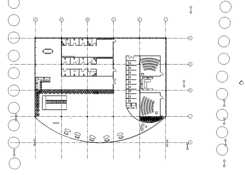
4) Change the front walls to the curtain walls- external galzed wall as per question
5) Copy the entire thing to all the levels ie first floor , second floor and third floor
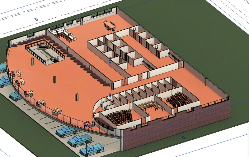
6) Roof option creates a roof using the building footprint to define its boundaries.
- Display a floor plan view or a reflected ceiling plan view.
- Click Architecture tab>Build panel>Roof drop-down>Roof by Footprint
If we try to add a roof on the lowest level, a dialog prompts you to move it to a higher level. If we choose not to move the roof to a different level, Revit notifies you later if the roof is too low.
- On the Draw panel, select a sketch or pick tool. To edit roof properties before sketching, use the Properties palette.
- Sketch, or pick, a closed loop for the roof.
- Specify slope defining lines. To change the slope definition of a line, select the line and, on the Properties palette, click Defines Roof Slope. We can then change the slope value.
- Click Finish Edit Mode, and then open a 3D view
On the upper side of glazed curtian wall make a roof ie glazed roof
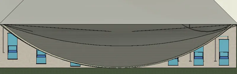
RESULT:
All the following components on the structure selected are inserted
5) Provide a set of drawings in an architectural and structural model to list the following details with categories and appropriate sheet templates included
a. Floor Plans with Annotations
b. Elevations
c. Sections
INTRODUCTION:
An architectural model is a type of scale model – a physical representation of a structure – built to study aspects of an architectural design or to communicate design ideas. Depending on the purpose, models can be made from a variety of materials, including blocks, paper, and wood, and at a variety of scales.
Architectural models are used by architects for a range of purposes:
- Ad hoc models, or sketch models, are sometimes made to study the interaction of volumes, different viewpoints, or concepts during the design process. They may also be useful in explaining a complicated or unusual design to builders, or as a focus for discussion between designers and consultants such as architects, engineers and town planners.
- Presentation models can be used to exhibit, visualize or sell a final design. A model is also used as show pieces, for instance, as a feature in the reception of a building, or as part of a museum exhibition such as scale replicas of historical buildings.
Types of models include:
- Exterior models are models of buildings that usually include some landscaping or civic spaces around the building.
- Interior models are models showing interior space planning, finishes, colors, furniture and beautification.
- Landscaping design models are models of landscape design and development, representing features such as walkways, small bridges, pergolas, vegetation patterns and beautification. Landscaping design models usually represent public spaces and may, in some cases, include buildings as well.
Structural Model Elements are, literally, elements that support a structure such as columns, rebar, trusses, and so on. This section discusses how to manipulate these elements.
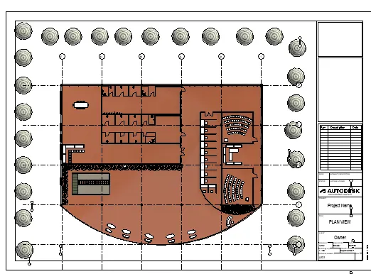
In architecture and building engineering, a floor plan is a technical drawing to scale, showing a view from above, of the relationships between rooms, spaces, traffic patterns, and other physical features at one level of a structure.
Dimensions are usually drawn between the walls to specify room sizes and wall lengths. Floor plans may also include details of fixtures like sinks, water heaters, furnaces, etc. Floor plans may include notes for construction to specify finishes, construction methods, or symbols for electrical items.
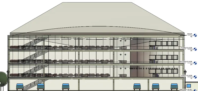
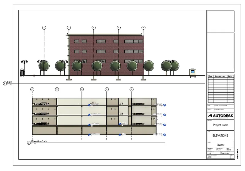
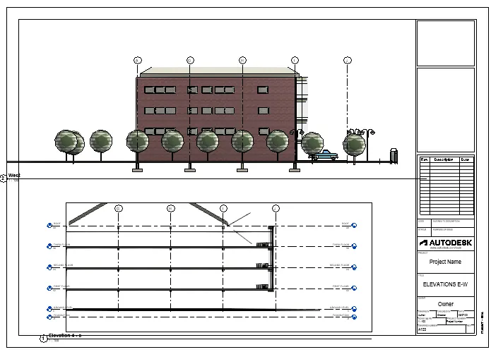
Elevation drawings are a specific type of drawing architects use to illustrate a building or portion of a building. An Elevation is drawn from a vertical plane looking straight on to a building facade or interior surface. This is as if you directly in front of a building and looked straight at it. Elevations are a common design drawing and technical architectural or engineering convention for graphic representation of architectureElevation views are part of the default template in Revit. When you create a project with the default template, 4 elevation views are included: north, south, east, and west. It is in elevation views where you sketch level lines. For each level line that you sketch, a corresponding plan view is created.Model's exterior or interior elevation perspectives from four default template directions or other directions that you specify.
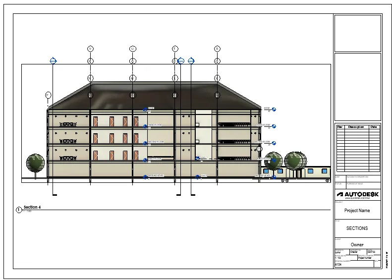
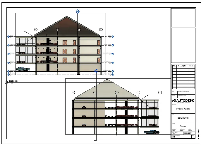
Section drawings are a specific type of drawing architects use to illustrate a building or portion of a building. A section is drawn from a vertical plane slicing through a building. This is as if you cut through a space vertically and stood directly in front looking straight at it. Sections are a common design drawing and technical architectural or engineering convention for graphic representation of architecture. Section drawings are orthographic projections (with the exception of section perspectives). This means they are not drawn in perspective and there is no foreshortening.
PROCEDURE:
1) Create a Sheet
- Click View tab>Sheet Composition panel>Sheet
- In the New Sheet dialog, under Select titleblocks, select A1 Metric, and click OK.
- Click the title block to select the sheet, then click the sheet number, enter A1, and press Enter.
2) Add Views to the Sheet
- In the Project Browser, under 3D Views, click the View to Building view title and drag it to the upper right corner of the sheet, and release the mouse button.An outline of the view displays for easier placement.
- Click to place the view.
- Using the same method, drag theplan view to the sheet, and place it in the sheet
RESULT:
The views are added to sheets accordingly
PLAN VIEW:
ELEVATION VIEW:
SECTIONAL VIEW
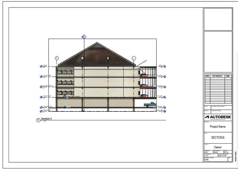
6) Using the Rendering settings, Render images of the 3D model produced and include the rendered images to the drawing sheets
a. Rendering from interior rooms
b. Rendering from out showing topographic features
c. Rendering through structural framing
INTRODUCTION:
Rendering is a digital processing of a 3D (three-dimensional) model into a 2D (two-dimensional) image, resulting in an image with a high degree of realism.By default, 3D model is displayed at a low or simplified resolution, saving your computer's processing and memory, but are free to generate rendered images of our project.
Revit begins the rendering process, rendering the entire image progressively. Revit displays a progress dialog, which shows information about the rendering process.When the rendering process is complete, Revit displays the rendered image in the drawing area.We can then do the following:
- Change render settings, and render the image again.
- Adjust exposure settings, and render the image again.
- Save the rendered image as a project view.
- Export the rendered image to a file.
- Display the building model in the drawing area.
In the Rendering dialog, click Show the model. To display the rendered image again, click Show the rendering.
PROCEDURE:
After preparing the 3D view and using the Rendering dialog to select desired settings
Click Render to render the image.
RESULT:
Rendering of certain views are added in sheets
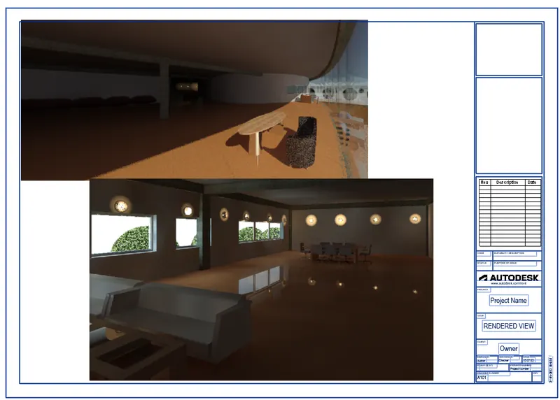
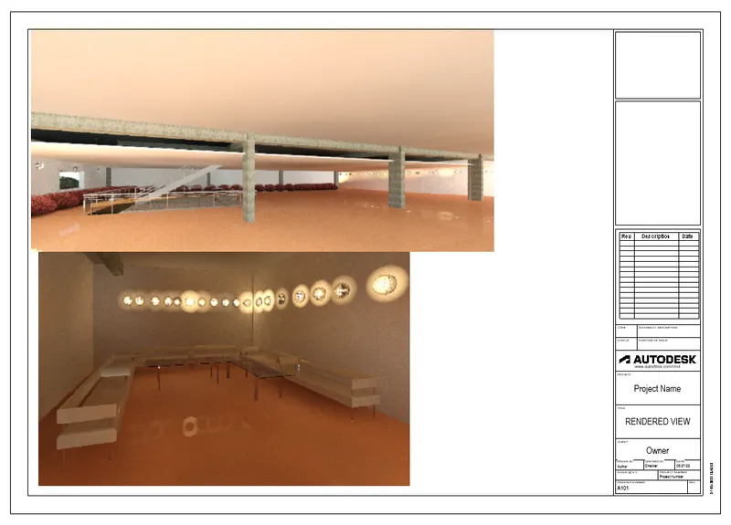
Interior rooms: Reception and confrence room
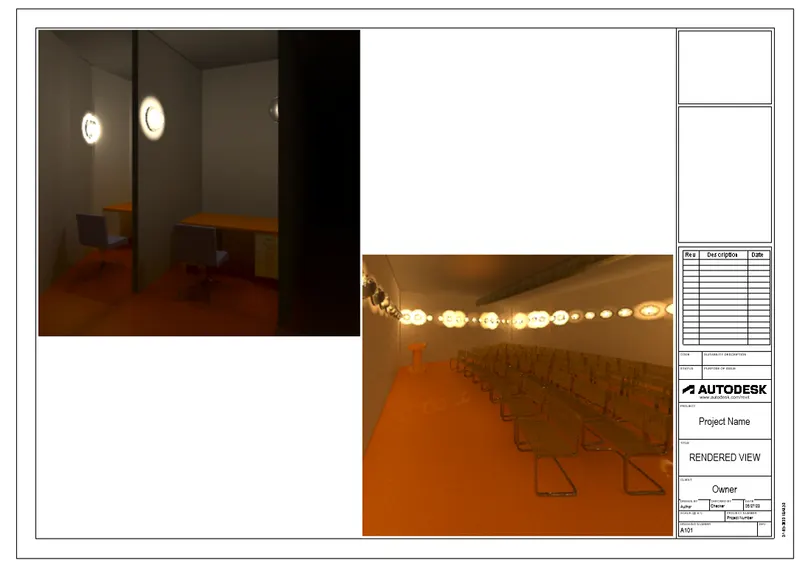
Office cabin and Auditorium
Topographic features
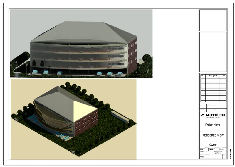
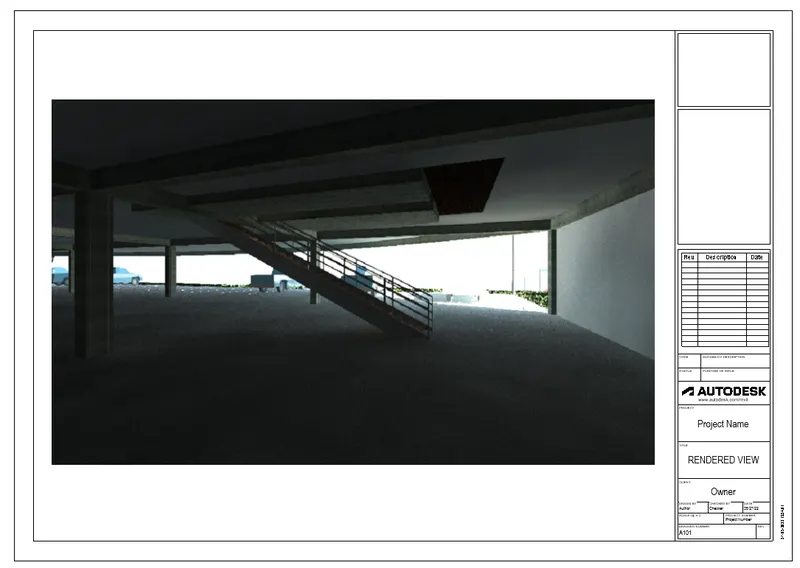
Through structural framing
Beams and columns are visible
7) Print the set of drawing sheets created and submit the drawings from the architecture and structure model
INTRODUCTION:
We the Print tool to print selected views and sheets..If we have to print a large number of views and sheets, consider using Batch Print for Autodesk Revit.
PROCEDURE:
- Click File tab>Print
- In the Print dialog, for Name, select a printer.
- Click Properties to configure the printer.
- Select Print to File. You can save the print job as a PRN or PLT file.
To print to PDF, do not use this option. Instead, select a PDF print driver in the Name field
RESULT:
Sheets are printed sucessfully