Creating Architectural and Structural model with 3D rendering using REVIT
1.
Aim
To select the type of building for modelling. To take the location of building and other parameters.
Procedure
- I have selected Multi-storey residential building with G+2 stories.
- The building is located in Bangalore
- The height of building is 10.5m
- The width of street road is 30m
- There is no electrical supply in front and above the plot
- The size of plot is 15m x 20m
Result
Thus the Multi-storey residential building has been selected for modelling.
2.
Aim
To get the required data for modelling the building and to check with the NBC Guidelines.
Procedure
- As per NBC the size of the plot for residential building is 250Sqm. My model is of about 300Sqm which is greater than NBC guidelines. And the frontage is above 12m.
- From table 3 of NBC 2016 part 3 the open space for Residential building is 3m on both sides.
- As per NBC 2016 Part 3 of Page 40 the maximum Height of building shall not exceed 1.5 times the width of street road.
- In my model the width of road is 30m.
- As per NBC the Stair case details for Residential Building, Minimum width of stair is 0.75m
- Minimum thread of stair is 250mm to 300mm
- Maximum height of riser is 150mm
- Number of risers limited to 12 per flight.
- As per NBC part 3 page 33 the high voltage cable crossing the building
- For flat roof, open balcony and veranda, Line above the building vertical distance of 2.5m from the highest point.
- For line passing adjacent to building horizontal clearance of 1.2m from nearest point.
Result
Thus the building is considered as per the NBC guidelines.
3.
Aim
To create Foundation, Columns, Beams, Floors, Roofs and Floor Openings.
Procedure
- Open the existing project with grids.
- Go to structural tab and click on columns.
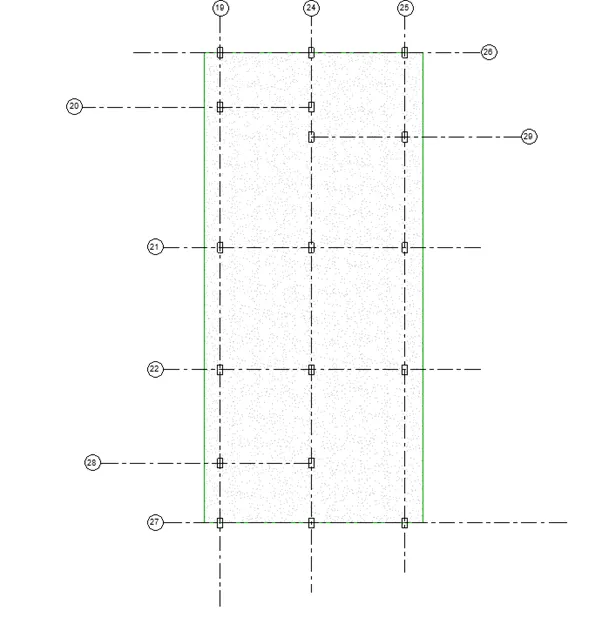
- Click size of column and use at grid option and select all grids and press enter.
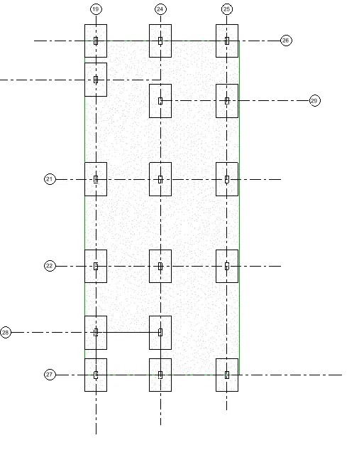
- Then for foundation select foundation and use at column option and select all grids press ok.
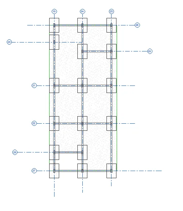
- Go to structural tab and press beam and select appropriate beam
- Then select on grid option then select all the grids and press ok.
- Thus the columns foundation and beams are created.
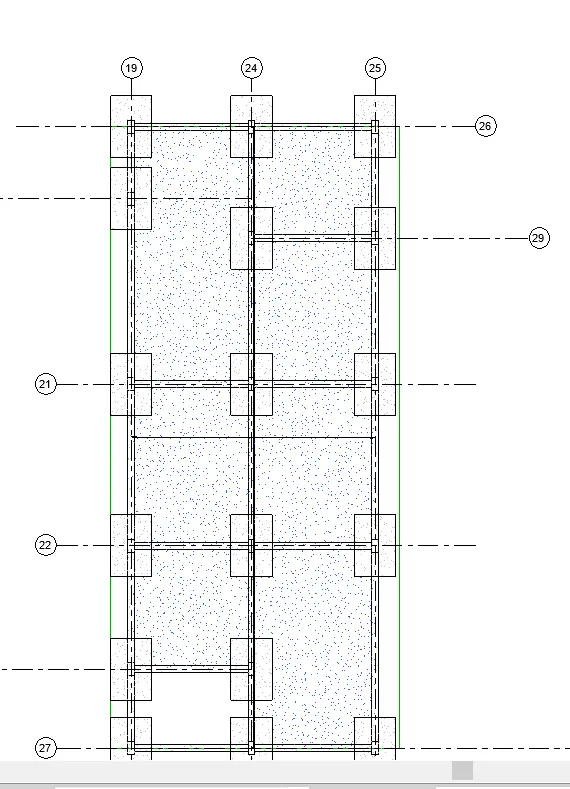
- Then select floor tab and select the floor area and press enter.
- Then go to architectural tab and select shaft and create shaft opening
- Thus the floor and shaft opening has been created.
Foundation
Columns
Beams
Floor
Shaft Opening
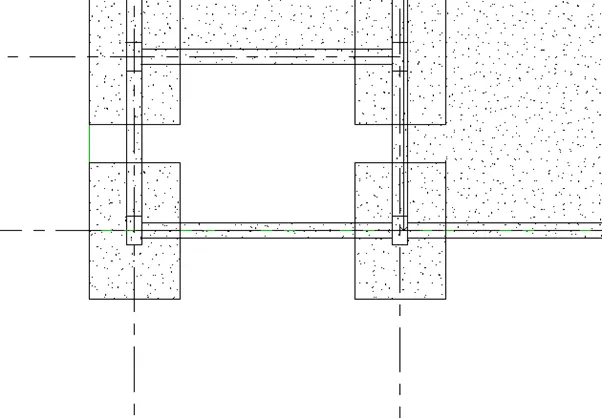
Overall Result
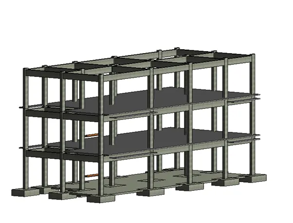
Result
Thus the foundation, columns, beams, floors and roofs with shaft openings are created in the structural drawing
4.
Aim
To create walls, interior partition walls, components to add details, stairs, lighting fixtures and topography components for outside etc.
Procedure
- Go to architectural template and draw walls in the grids.
- Then after drawing walls place doors and windows at appropriate location.
- Then place furniture’s like sofa in living dining table, bed, study desk, wardrobe, kitchen equipment’s, etc. by choosing component and in load family.
- Then place wall lights, celling lights, interior lights and exterior lights to the model.
- Ad stair case to the model in the place of shaft.
- Then place topography components to the model.
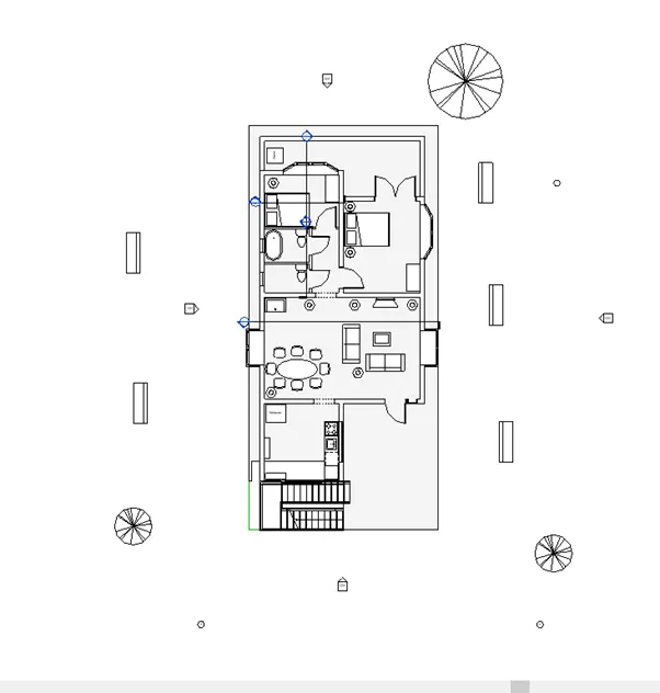
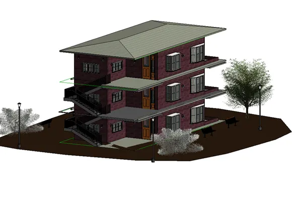
Result
Thus walls, interior partition walls, components to add details, stairs, lighting fixtures and topography components for outside etc. are created.
5.
Aim
To create sheets for all the views and section views of all the rooms
Procedure
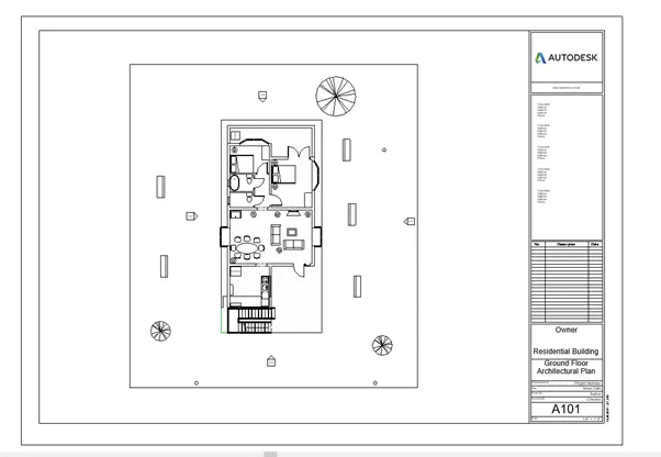
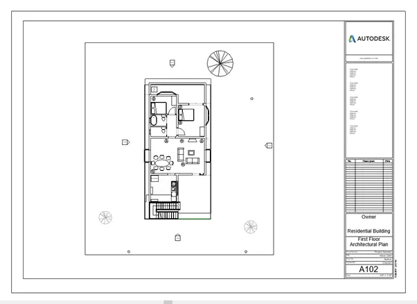
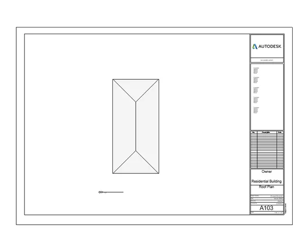
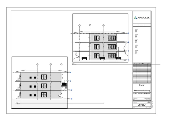
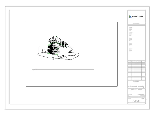
- Go to view tab there is a option called sheets click on it and choose size of sheet and the press enter sheet will be created then place the appropriate plans and views in it.
- Drag the floor plan and place in the sheet.
- Then create the sheet and then choose the first floor plan drag it and place in the sheet.
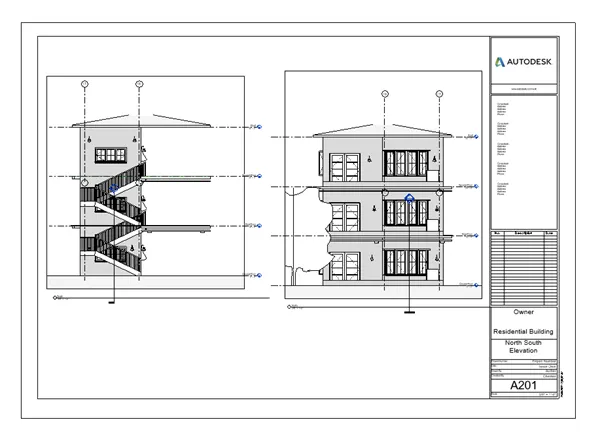
- Similarly create all the plan views and elevation views in the sheet.
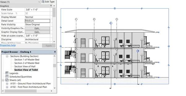
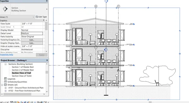
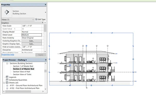
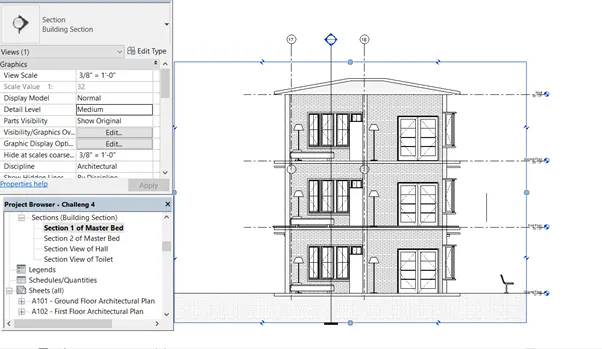
- Then create section views in view tab there is a option called section click on it and cut the model in the appropriate location.
- Thus a section view is created.
- Rename the view and similarly create different section views.
- Thus the plan elevation and section views are created.
Result
Thus the plan, elevation and section view are created and placed in the sheet.
6.
Aim
To create a rendered image of different views.
Procedure
- Open the existing Revit model in which we have created the camera views and sheets.
- We have already created the camera views in that model.
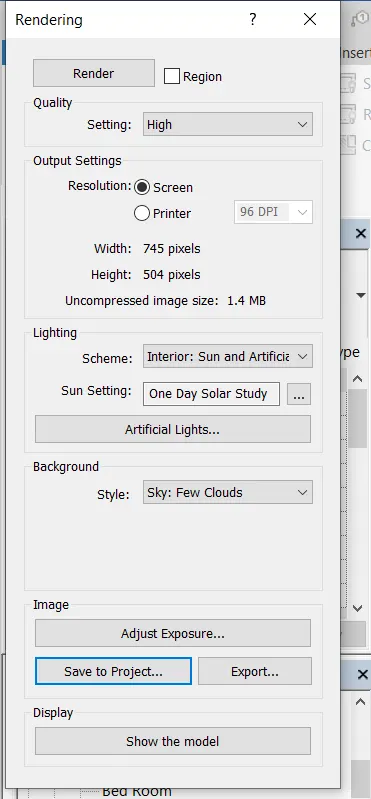
- Go to the camera view and enter RR for rendering dialogue box.
- Or we can render by using view tab.
- Once the rendering dialogue box opened we can edit the quality lighting and other settings.
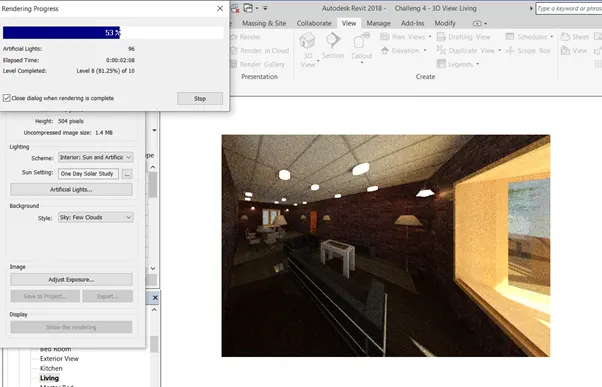
- Then in the top left there is option called render click on it to start rendering.
- Depends upon the quality it will take time to render.
- Once rendering completed save the image to the model.
- Thus the rendered image has been created
- Similarly create some other 3D camera view and start rendering.
Living
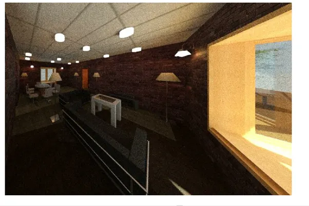
Bed Room
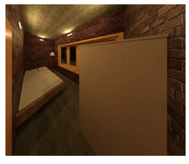
Master Bed Room
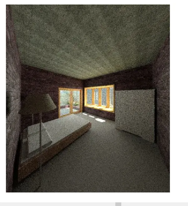
Kitchen
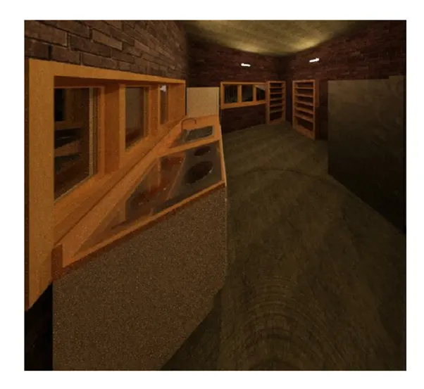
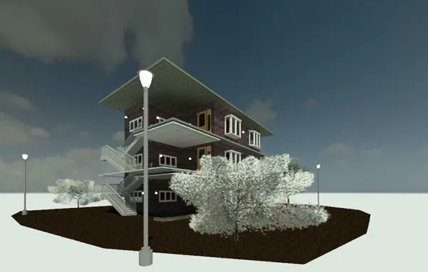
Exterior View
Result
Thus the rendered image of different views are created.
7.
Aim
To print the views and make it as a pdf.
Procedure
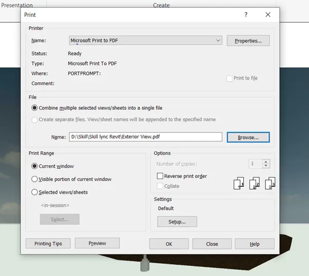
- For printing go to the sheet or image and press ctr+p
- Print dialogue box will appear.
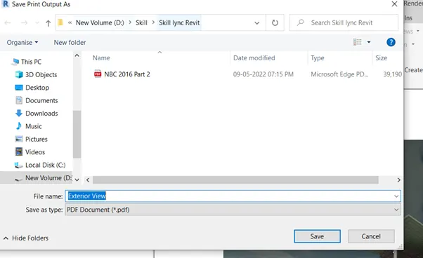
- In this select Microsoft to pdf option and select the destination file.
- Press save the view is saved.
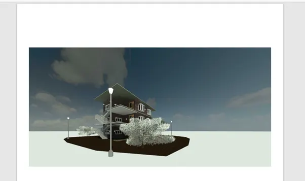
- Similarly repeat the same procedure for all the sheets and images which ever need to be printed.
Result
Thus the print and save to pdf is generated and saved