Creating Architectural and Structural model with 3D rendering using REVIT
1) Select the type of structure you want to build from one of the three below:
a. Multi-Unit Residential Apartment
b. Office Buildings
c. School
Aim: To select type of the structure for modelling in the revit software
Introduction:
- Depending upon the type of structure the design considertion of building fot the modelling purpose vary.
- So it is important to clarify the type of structure before starting any project so that t will serve its functionality for which it is being modelled.
Procedure:
- Type of structure from above three, I chose A.Multi storey residential apartment.
- It is G+2 Residential apartment.
Result:
Therefore type of structure is selected as multi-unit residential apartment in the Revit.
2) Assume reasonable assumptions for geographic and location details for your project modeling. Based on assumptions and type of structure selected identify the modeling requirements from NBC
Assumptions for geographic and location details for my project modelling
- My building is constructed in residential area
- My building is constructed in the plain area
- Infront of my building there is a road width of 100 feets.
- As per the NBC, the height limit will be given in NBC part V-1
- The size of the rooms also given in the NBC part V-1.
3) Using the structural model, include the following components based on the type of structure selected
a. Foundation – Isolated / Wall/Matt Foundation
b. Columns
c. Beams Connected to Columns
d. Roof Framing/ Truss
e. Floor / Decks
f. Floor Openings for Elevators and Stairs
Aim:
To include the foundations, columns, beams, floors, stairs in structural model in Revit.
Introduction:
- Beams and columns are two important types of structural elements that play a crucial role in creating a safe load path to transfer the weight and forces on a structure to the foundations and into the ground.
- Beams and columns could be built ysing the same shapes and materials but each serves a different function and is designed differently.
- A foundation is the lowest part of the building structure and it carry the whole structure and also it transfer loads from suoer structure to soil.
- It is the engineering field of study devoted to the design of those structures which support other structures, most typically buildings bridges or transportation infrastructure.
- It is at the periphery of civil, structural and geotechnical engineering disciplines and has distinct focus on soil-structure interaction.
Procedure:
step-1: Open RVT 2023
step-2: Select New template file
step-3: Select structural template
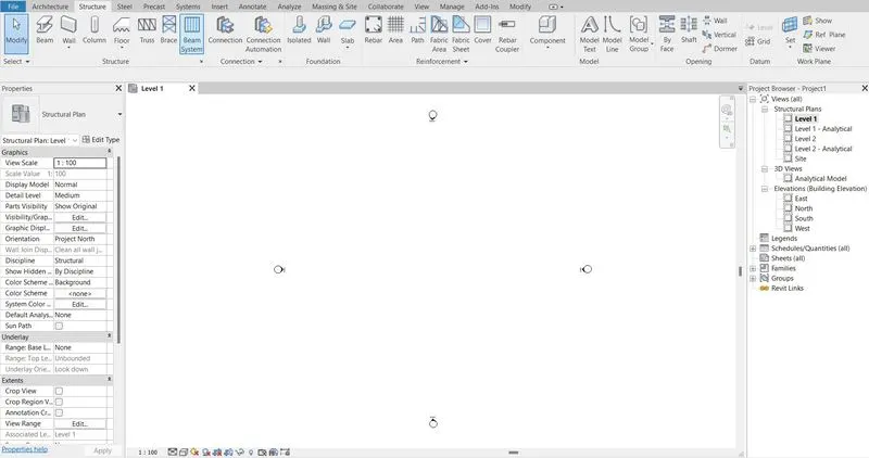
step-4: Go to structural tab
step-5: Select Grids

step-6: Select Line tool to draft grids on the floor plan
step-7: Select Pickline option and give offset distanse to draft remaining grids on the plane
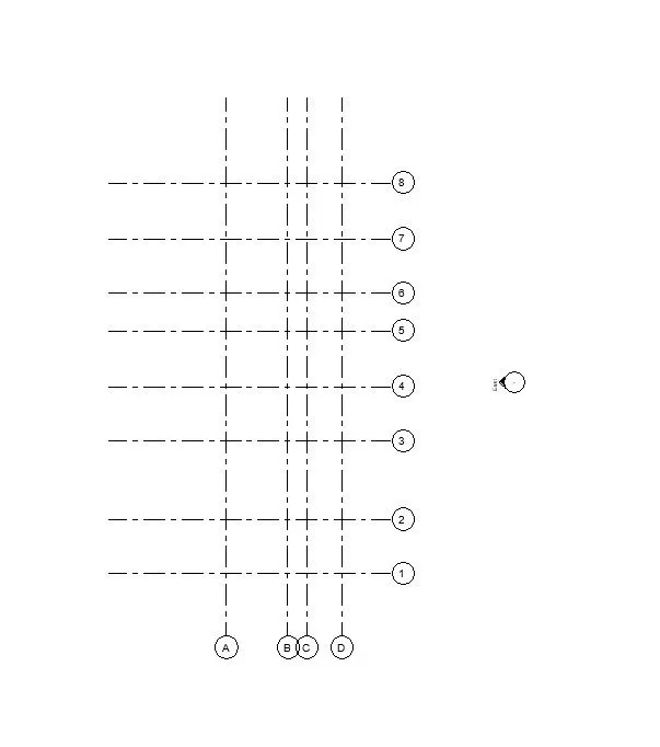
step-8: Go to structural tab
step-9: Go elevation view for drafting levels on the plan
step-10: Select Levels

step-11: Select pickline tool and enter specific distance to draw remaining levels according to the plan.
step-12: And again go to structural tab
step-13: Select column option
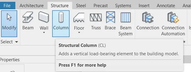
step-14: Select the grids which we required to place the column for load bearing from top level.
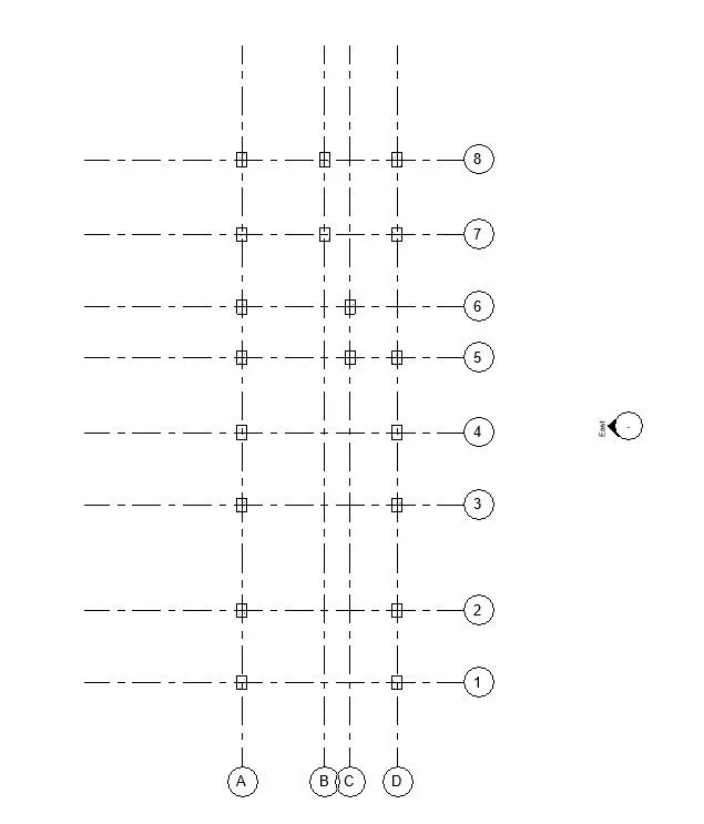
step-15: Go to structural tab
step-16: Select Isolated footing from foundations tab
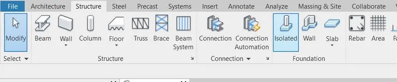
step-17: Select the required grids to plot isolated footing
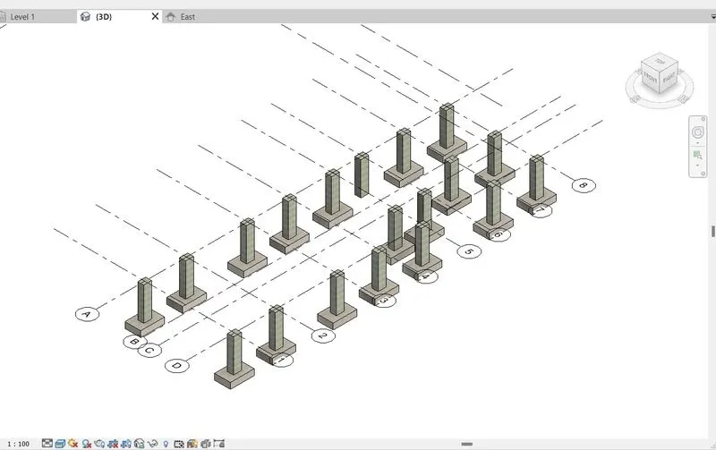
step-18: Go to structural tab
step-19: Select Beam
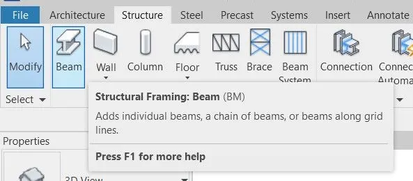
step-20: Select the place where beam is provided
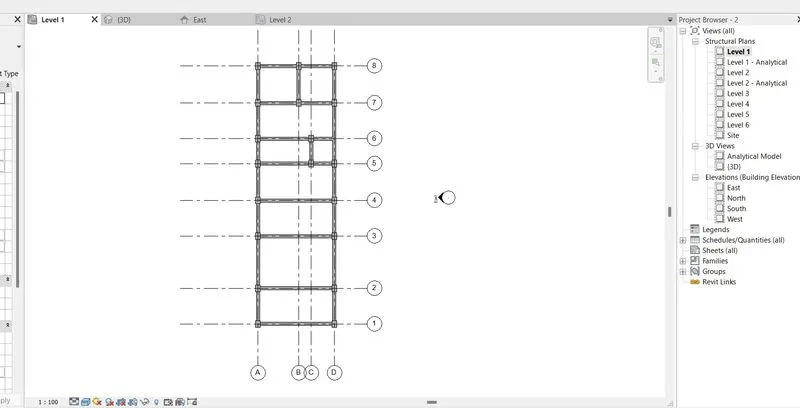
step-21: Go to structural tab
step-22: Select floors
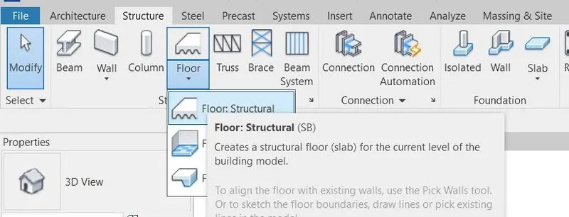
dtep-23: Select the levels to create floors
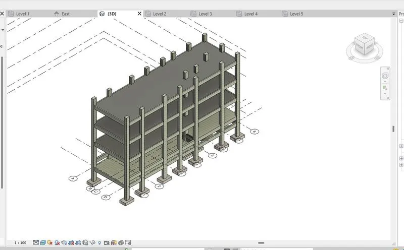
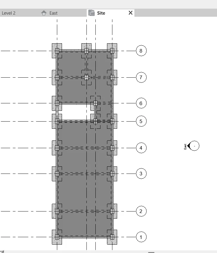
step-24: Select slab on foundations
step-25: Select bottom level to create slab foundation which means this foundation lies in soil.
step-26: Go to structural tab
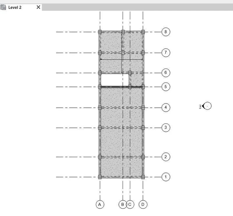
step-27: Select shaft opening

step-28: Select where we planned to locate stair case
step-29: Click ok to create opening from floor slab.
Result:
All structural elements are created by using Revit software.
4) Using the architectural model, include the following components based on the type of structure selected
a. Wall Layout with appropriate material and finishing
b. Exterior façade with fancy finish
c. Interior partition walls to size rooms
d. Components to add details to a room ( Desk, Chair, Lighting, Plumbing fixtures)
e. Add components such as stairs Elevators
f. Have at-least one side of the building with curtain walls and glass panels
g. Include interior and exterior lighting fixtures
h. Place proper topographic components from outside ( Trees, Parking, Plants) to add details to the model
Aim: To include wall layout, exterior facade, interior walls, furniture components, Curtains, blinds, lighting, parking and tress in architectural model by using Revit software.
Introduction:
- Partition walls are significant component of a building design, without partition walls a buildings plan cannot be decorative or structured.
- Lighting fixtures, come in a wide variety of styles for various functions
- The most important functions are as a holder for the light source to provide directed light and to avoid visual glare.
- Some are very plain and functional, while some are piece of art in themselves.
- Nearly any material can be used so long as it can tolerate the excess heat and is in keeping with safety codes.
Procedure:
step-1: Open RVT 2023
step-2: Click new file
step-3: Select Architectural layout
step-4: Go to Architectural
step-5: Select grids

step-6: Go to Elevation view in project browser
step-7: Go to architectural tab
step-8: Select levels
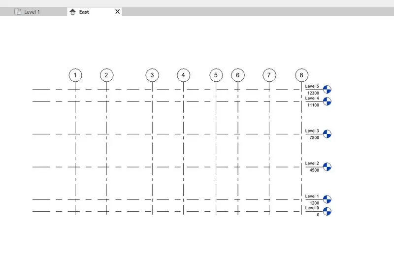
step-9: Go to Architectural tab
step-10: Select walls
step-11: Create wall on the floor plan
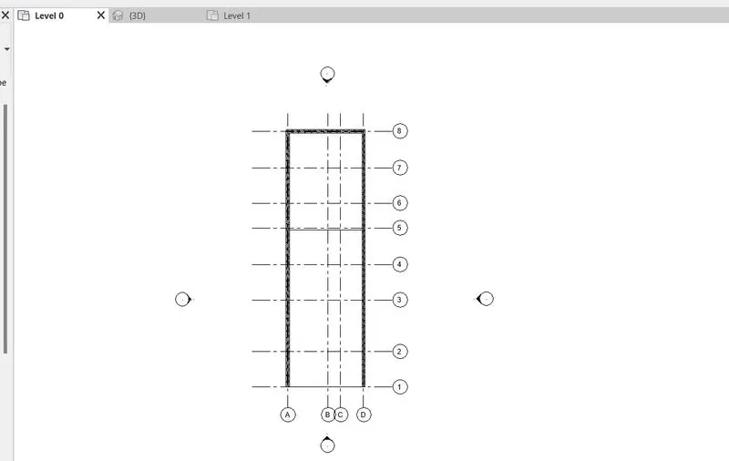
step-12: repeat the same step again to create entire wall layout on the plans
step-13: Mention the levels of the residential unit
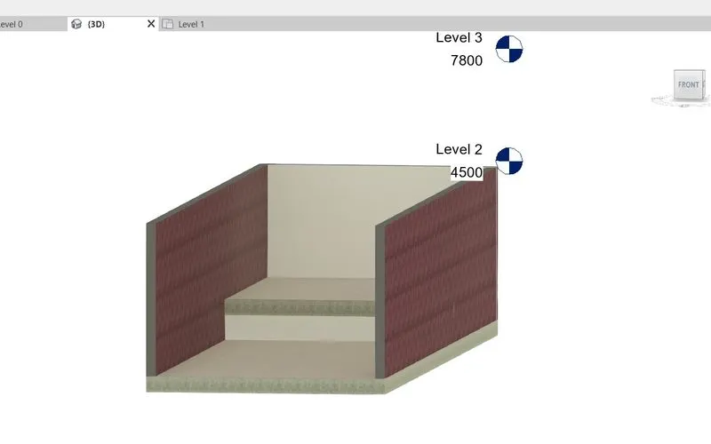
step-14: Ground floor wall layout
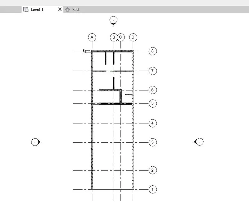
step-15: Ground floor side elevation
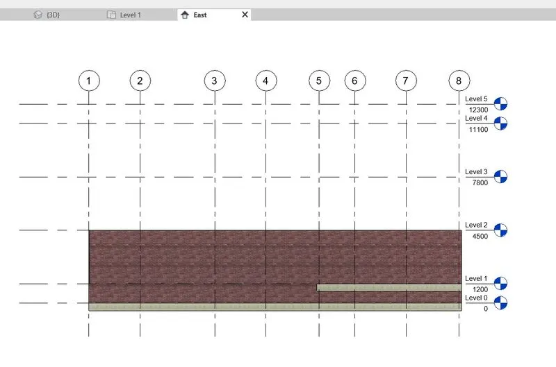
step-16: Ground floor Interior room partitions
step-17: Go to Architectural tab
step-18: Select floors
step-19: select rectangular tool and select boundary of the floor
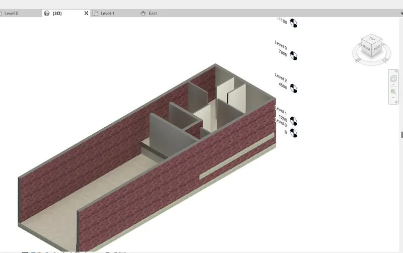
step-20: Go to Architectural tab
step-21: Select shaft opening
step-22: Go to Architectural tab
step-23: Select Staircase
step-24: Select the place to add staircase
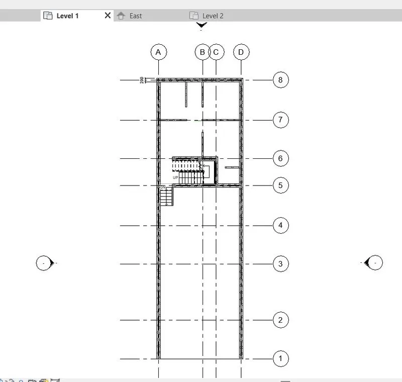
step-25: Create wall layout to first floor
step-26: Check 3D model
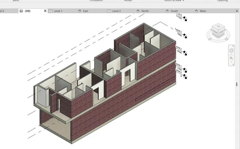
step-27: Insert staircase to first floor model
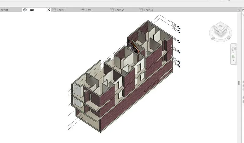
step-28: Copy all the elements in the first floor and paste it into the second floor
step-29: Create floor for second floor
step-30: Create shaft opening for staircase
step-31: Create staircase room for terrace floor
step-32: Parapet wall area created.
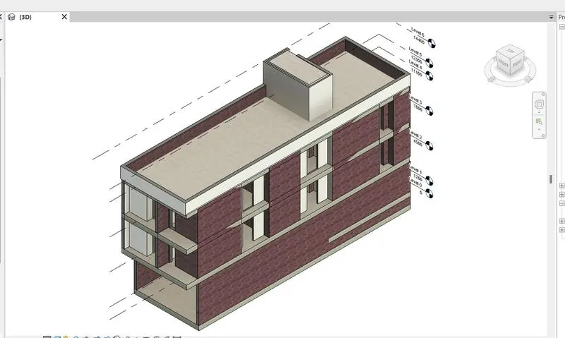
step-33: Door and window placing on floor plan
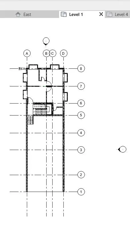
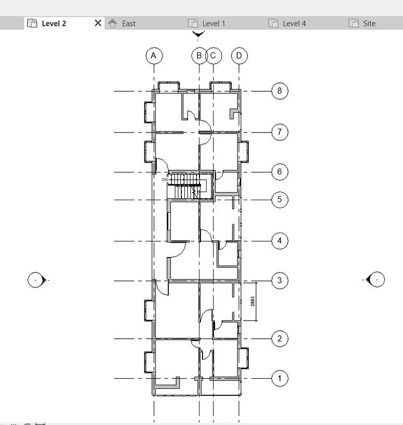
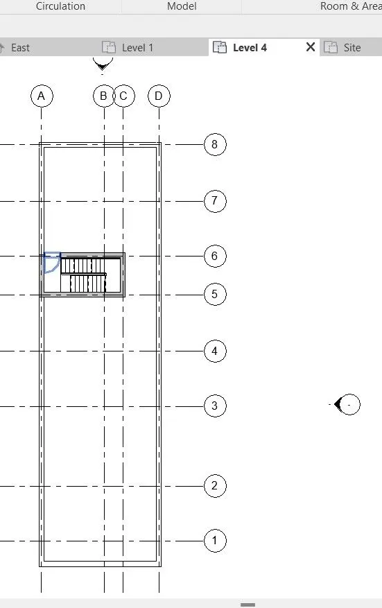
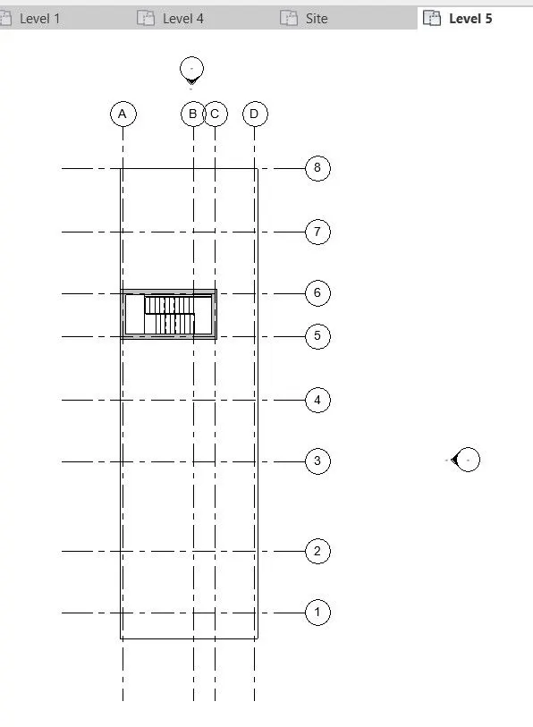
step-34: Add components like glaze panel for balcony area
step-35: Front balcony area
step-36: and also placed at Corridor area
step-37: Checking from side elevation of the residential unit
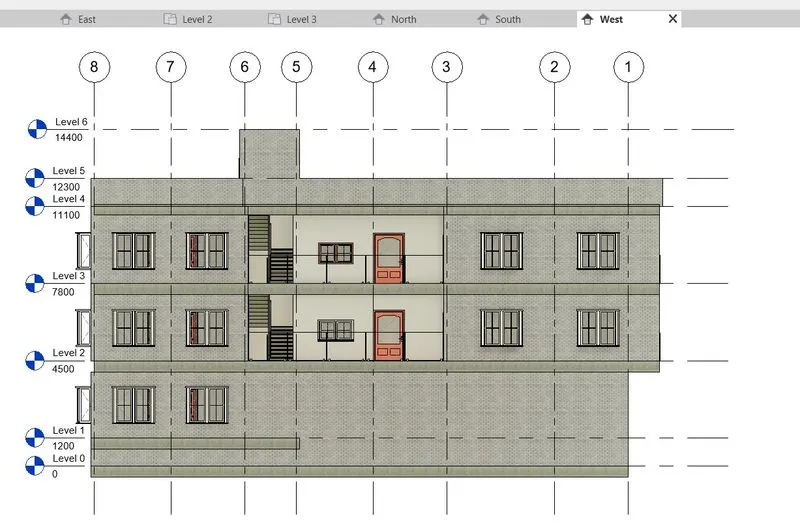
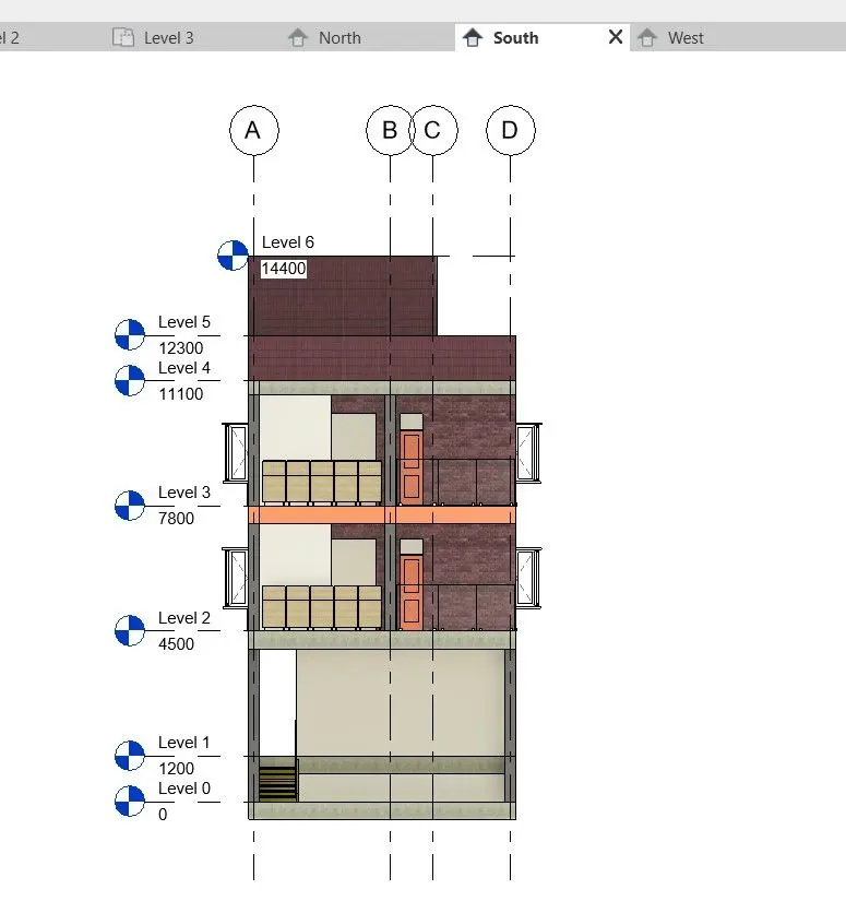
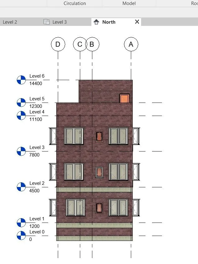
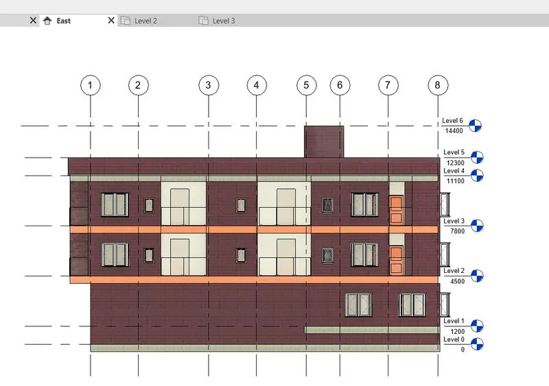
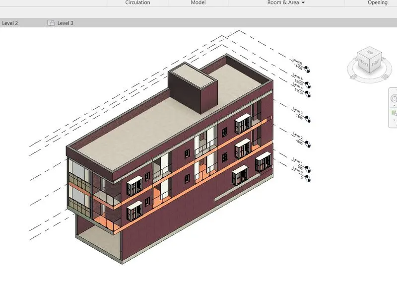
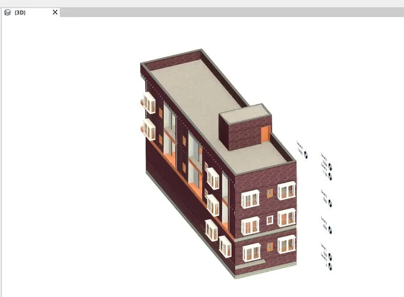
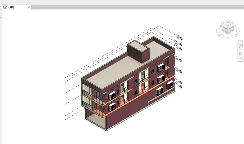
step-38: Room titles are given.
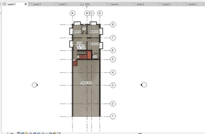
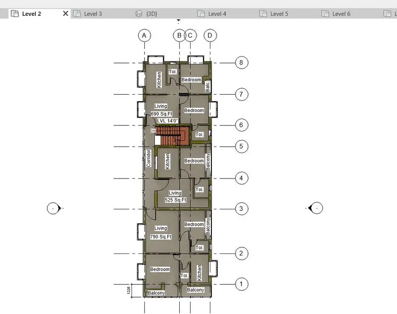
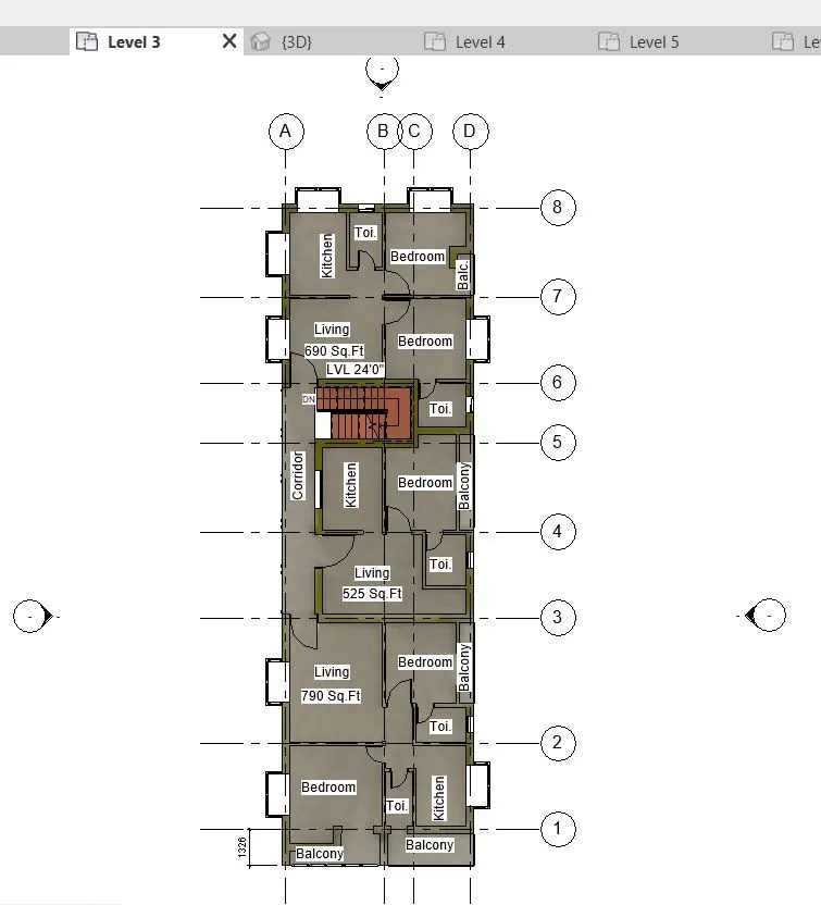
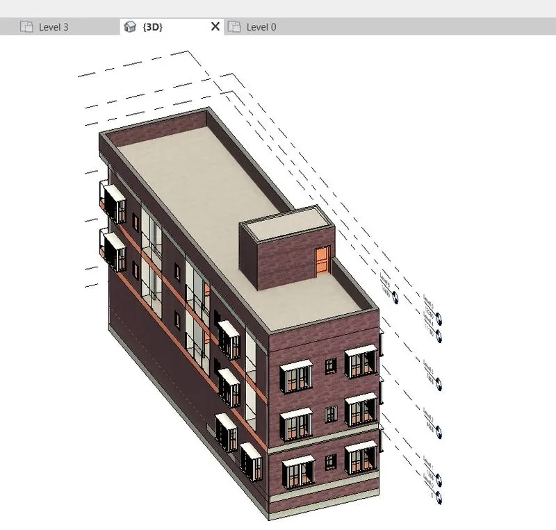
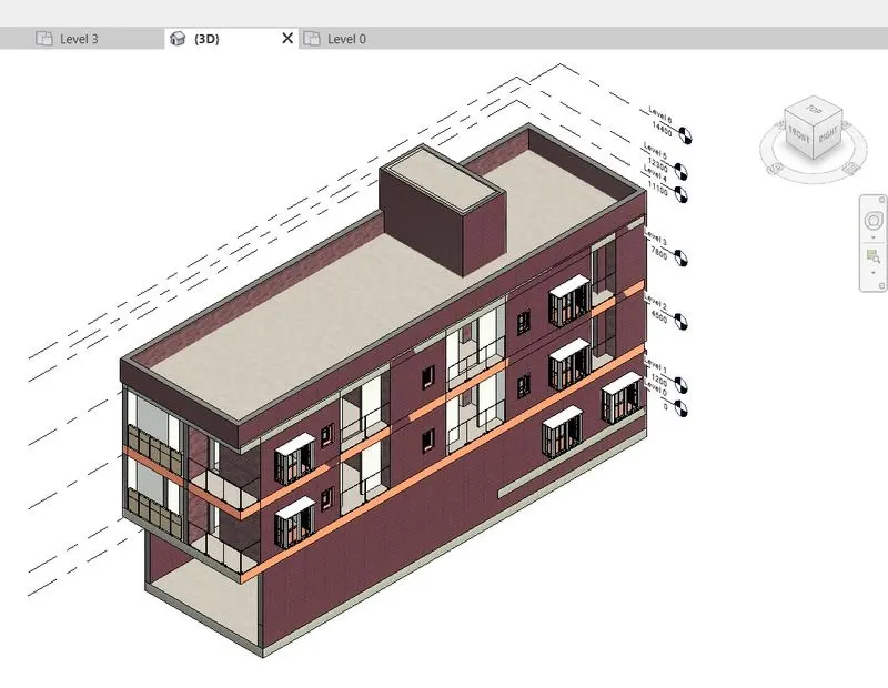
step-39: Go to VG
step-40: Search Texts
step-41: Hide all texts and to add furniture elements
step-42: Go to Architectural tab
step-43: Select add components
step-44: Select Load family
step-45: Go to library
step-46: Select the required components
step-47: Place it wherever it is needed.
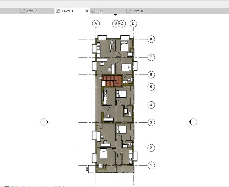
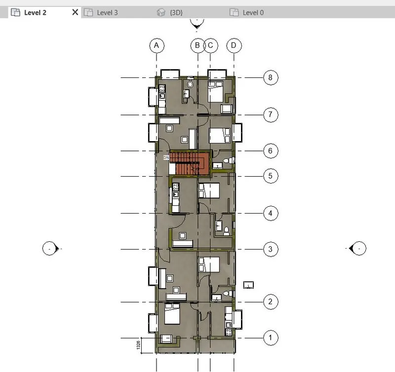
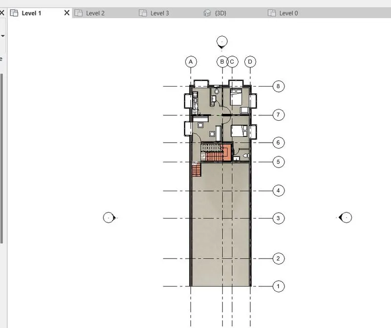
step-48: Go to Masssing ans site tab
step-49: Select Toposurface
step-50: Check whether visual graphics is on or off
step-51: Select Placing with points
step-52: Place the point on the plane
step-53: Topo surface is added

step-54: Go to Massing and site tab
step-55: After inserting toposurface there will be option called building pad
step-56: Choose building pad
step-57: Mark aorund the building

step-58: Go to Massing and site tab
step-59: Select Site components
step-60: Select Tree
step-61: Place it in outside of the building for visual purpose

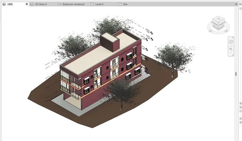
Result:
a. Wall Layout with appropriate material and finishing
b. Exterior façade with fancy finish
c. Interior partition walls to size rooms
d. Components to add details to a room ( Desk, Chair, Lighting, Plumbing fixtures)
e. Add components such as stairs Elevators
f. Have at-least one side of the building with curtain walls and glass panels
g. Include interior and exterior lighting fixtures
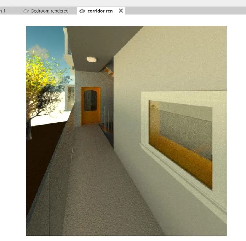
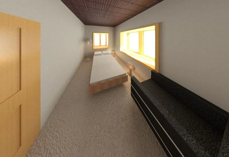
h. Place proper topographic components from outside ( Trees, Parking, Plants) to add details to the model
5) Provide a set of drawings in an architectural and structural model to list the following details with categories and appropriate sheet templates included
a. Floor Plans with Annotations
b. Elevations
c. Sections
Aim: To provide floor plans and elevation and section drawing we created in a last questions with proper drawing sheets
Procedure:
Step-1: Go to structural template and go to View Tab
step-2: Select sheets
step-3: Load A0 metric sheet
step-4: Drag elevation view from project browser
step-5: Change sheet title and other things
step-6: Placed with proper scale
step-7: Drag East view to sheet set
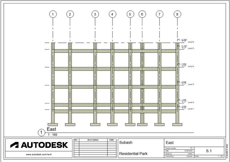
step-8: North view sheet set
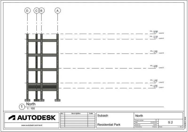
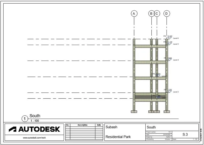
step-9: South view sheet set
step-10: West view sheet set
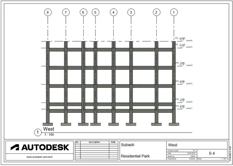
step-11: Section 1-1 sheet set
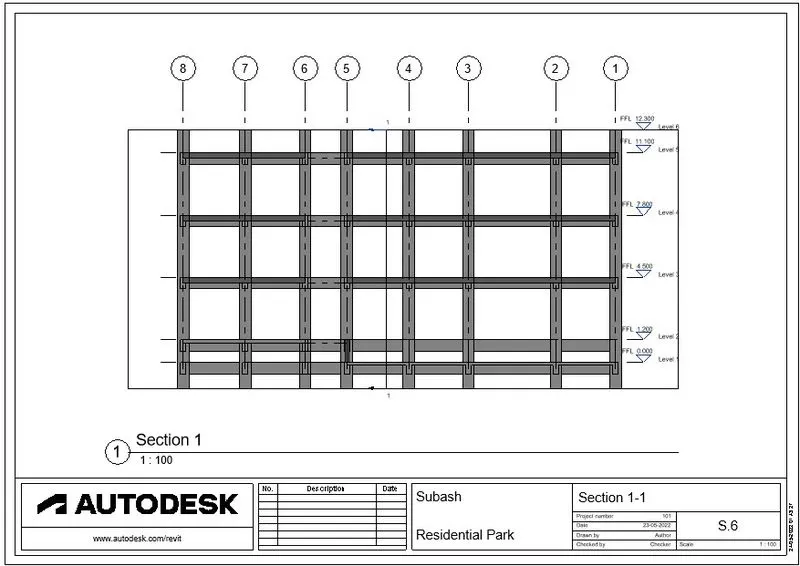
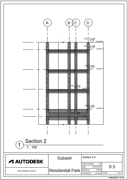
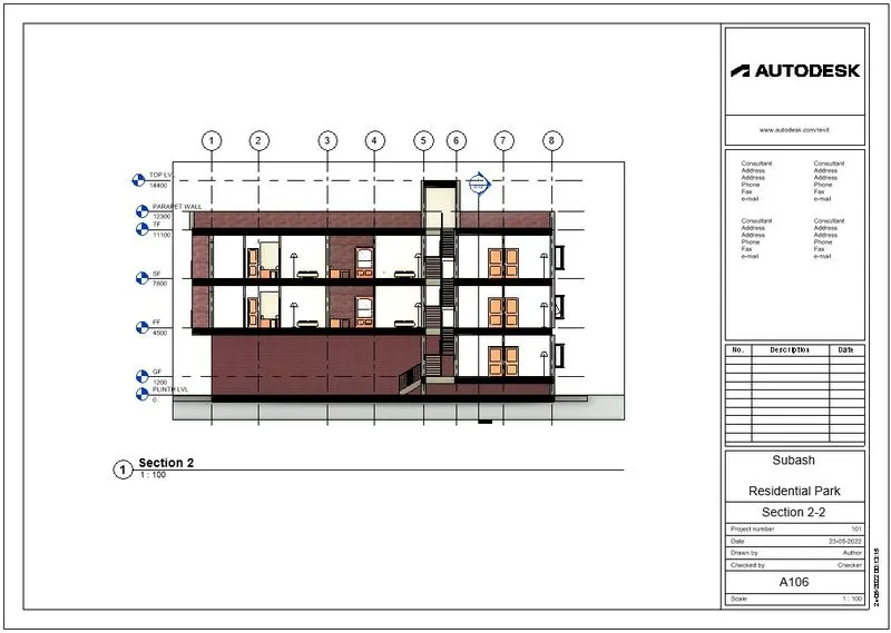
step-12: Section 2-2 sheet set
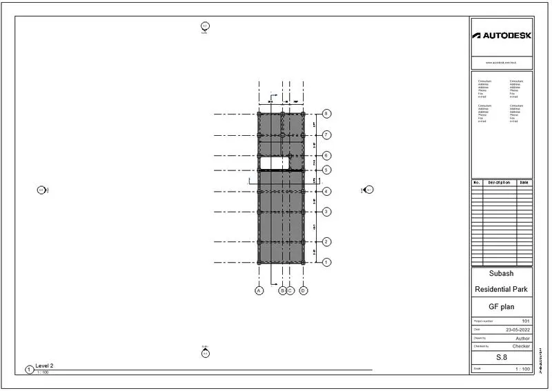
step-13: GF plan sheet
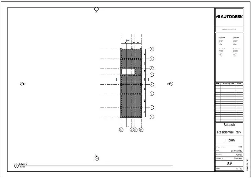
step-14: First floor plan sheet
step-15:Go to Archietctural template
step-16: Go to view tab
step-17: Select sheets
step-18: Drag view to appropriate sheets
step-19: East view sheet set
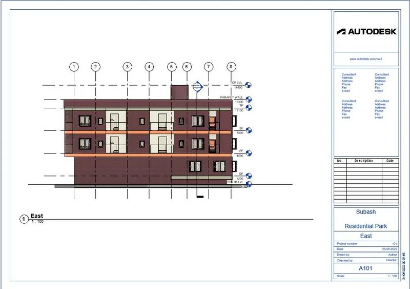
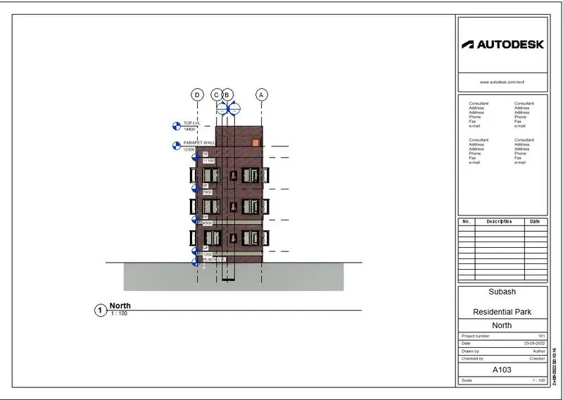
step-20: North view sheet set
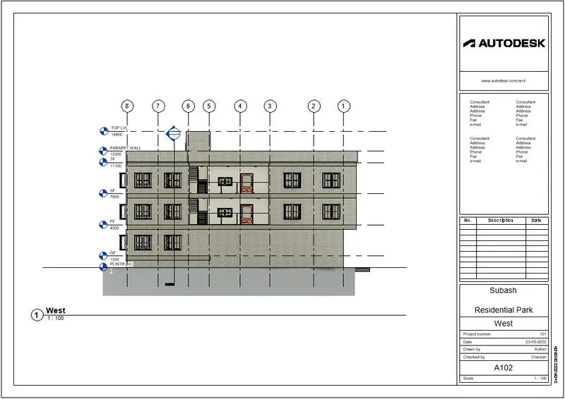
step-21: West view sheet set
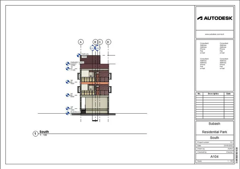
step-22: South view sheet set
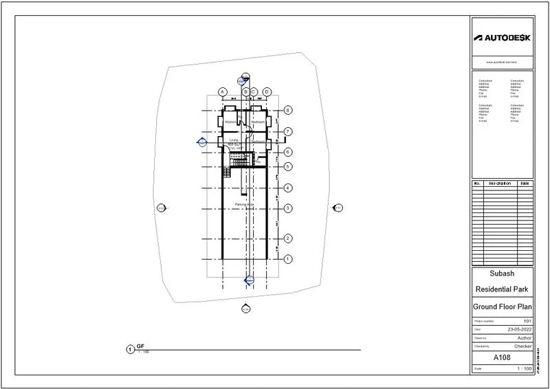
step-23: Ground Floor plan sheet
step-24: First floor plan sheet
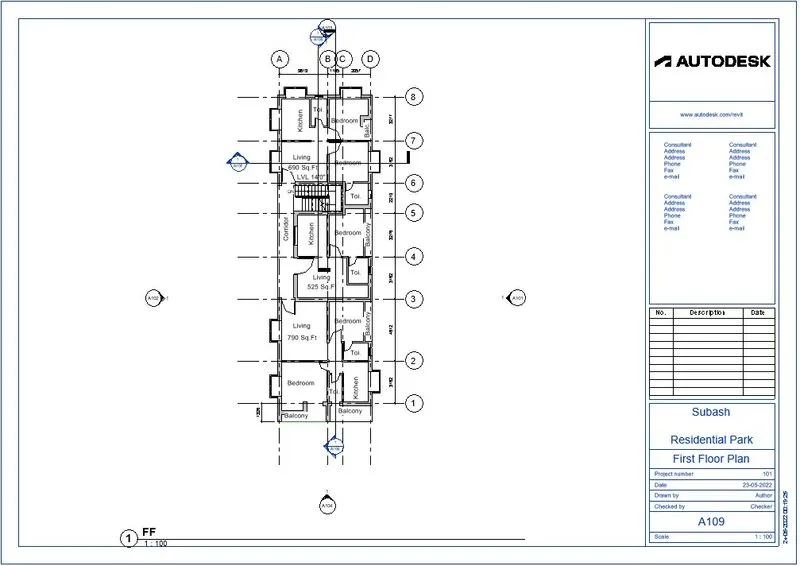
step-25: Second floor plan sheet
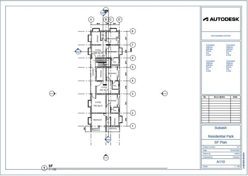
step-26: Terrace floor plan sheet
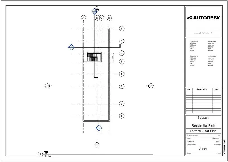
step-27: Section drawing taken from floor plan
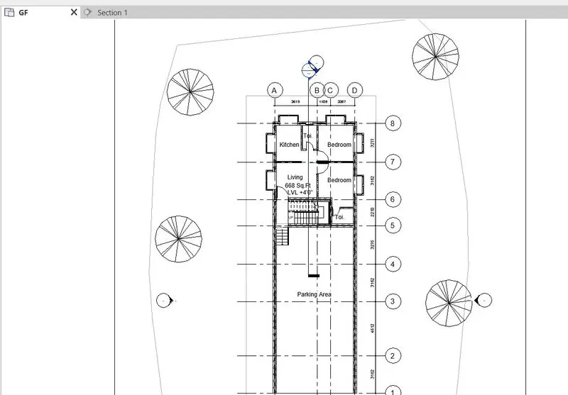
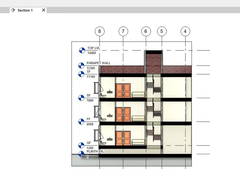
step-28: Section 1 sheet
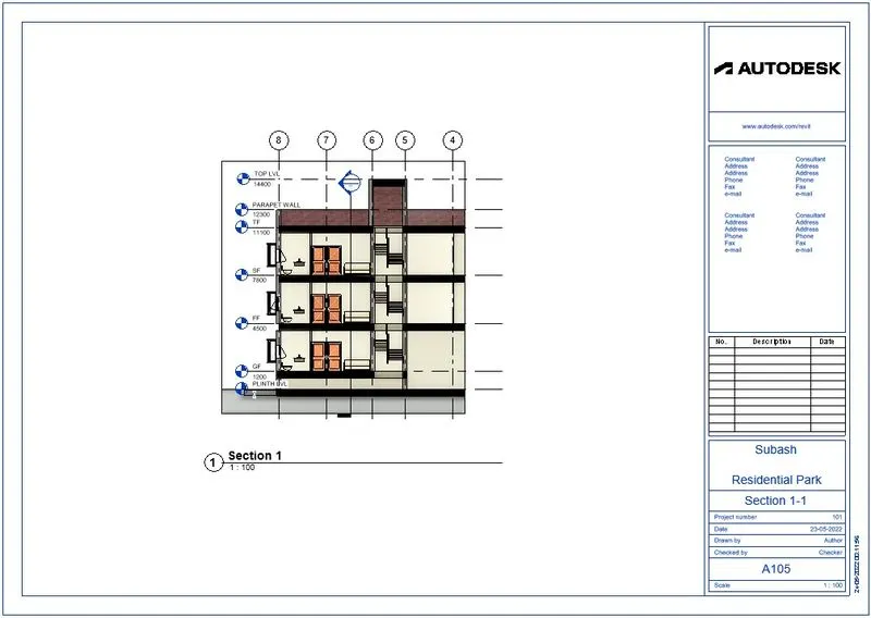
step-29: Section 2 sheet
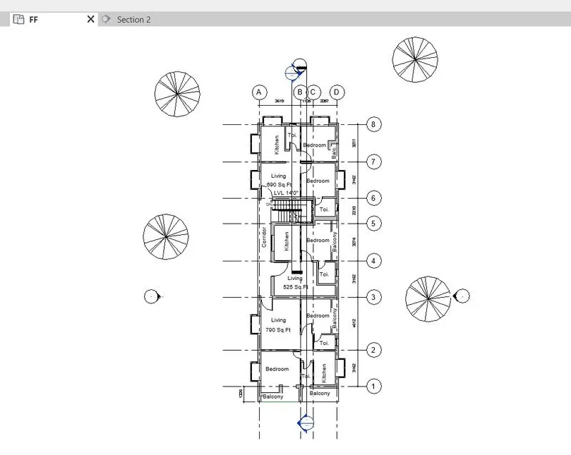
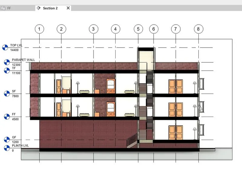
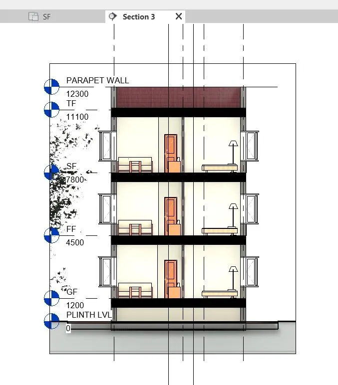
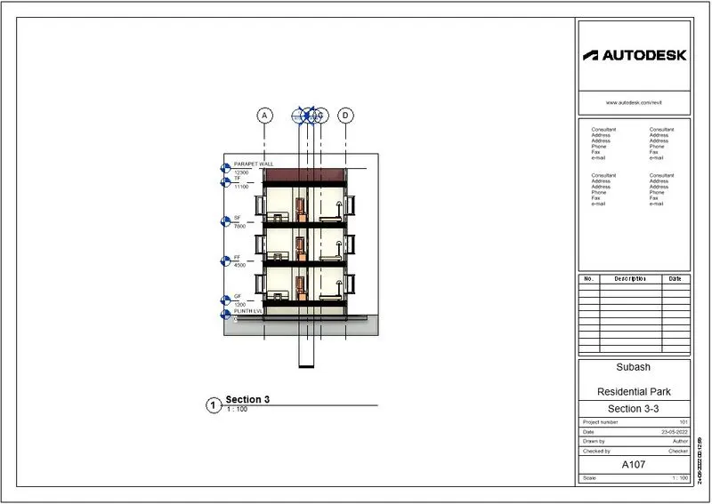
step-30: Section 3 sheet set.
Result:
All elevations, floor plans, section drawing sheets of architectural and structural models are included.
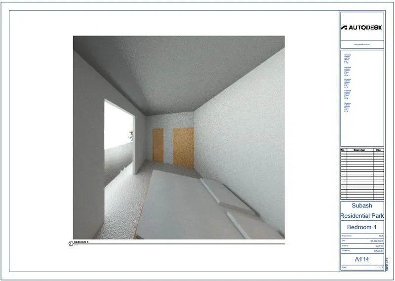
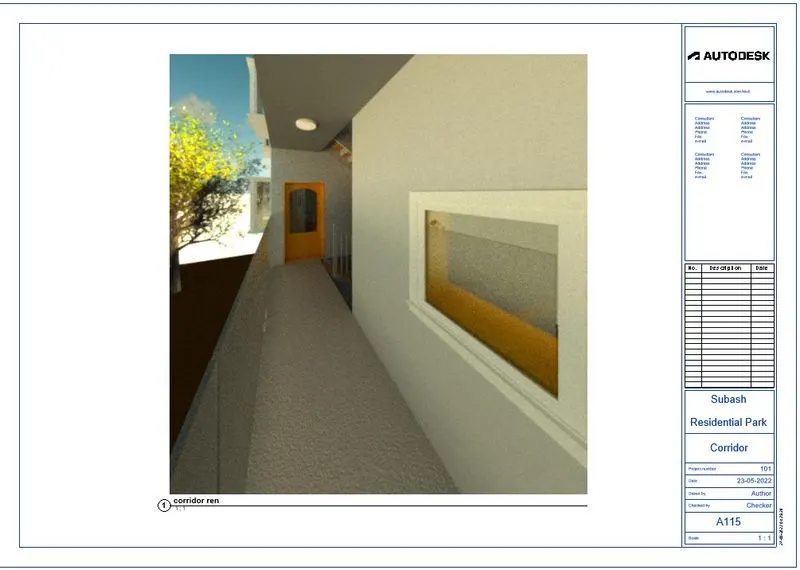
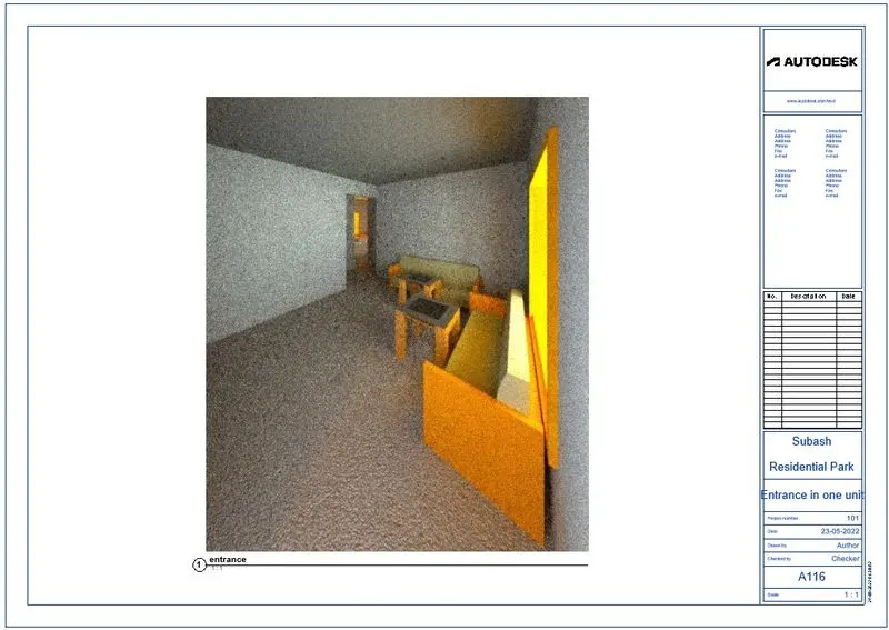
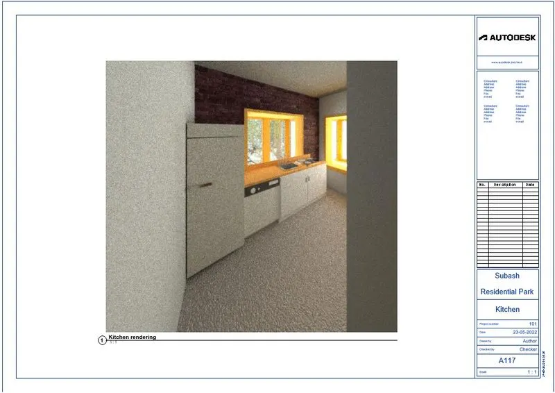
6) Using the Rendering settings, Render images of the 3D model produced and include the rendered images to the drawing sheets
a. Rendering from interior rooms
b. Rendering from out showing topographic features
c. Rendering through structural framing
Aim: To render the images from our architectural model and include in the drawing sheets
Procedure:
step-1: Go to the view we needed to render the image
step-2: Go to camera view
step-3: Select the view from plan
step-4: Go to view tab
step-5: Select Render option
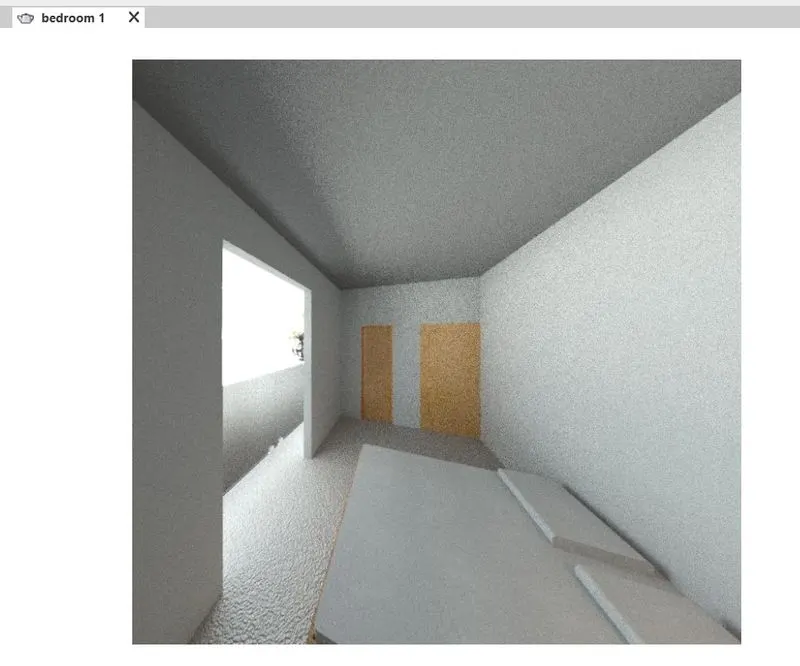
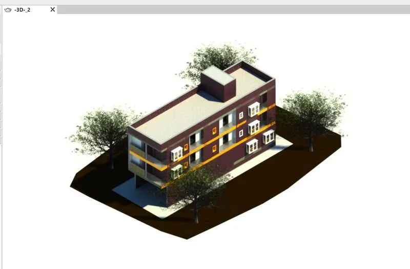
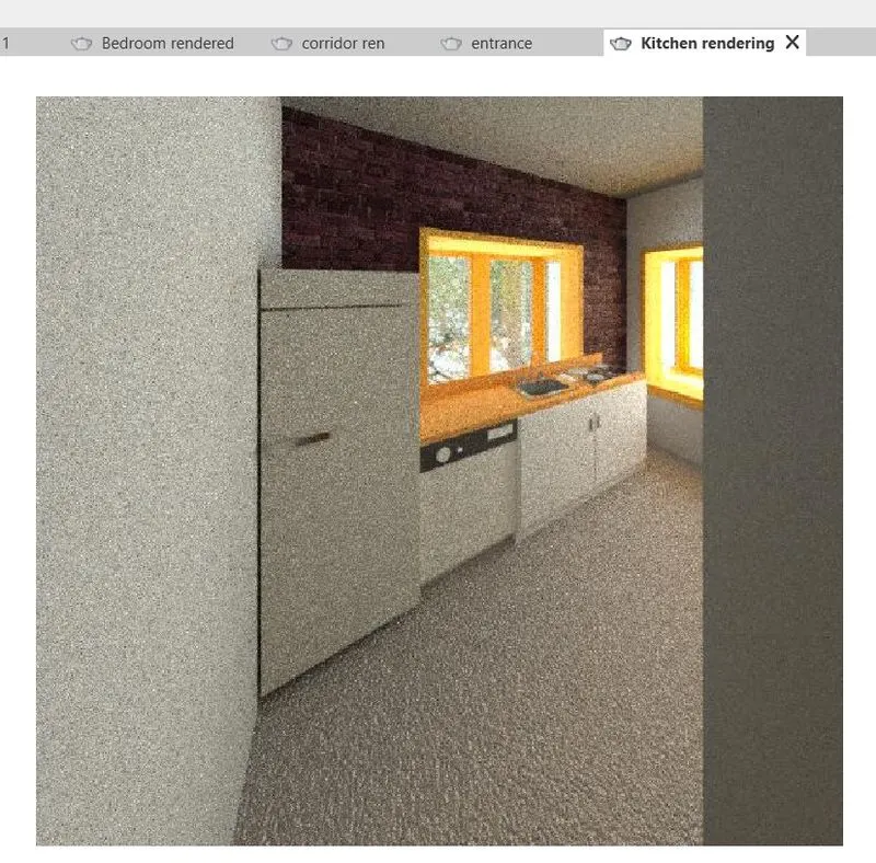
After rendering process, go to view tab and select sheets
step-7: Drag rendered images to sheets
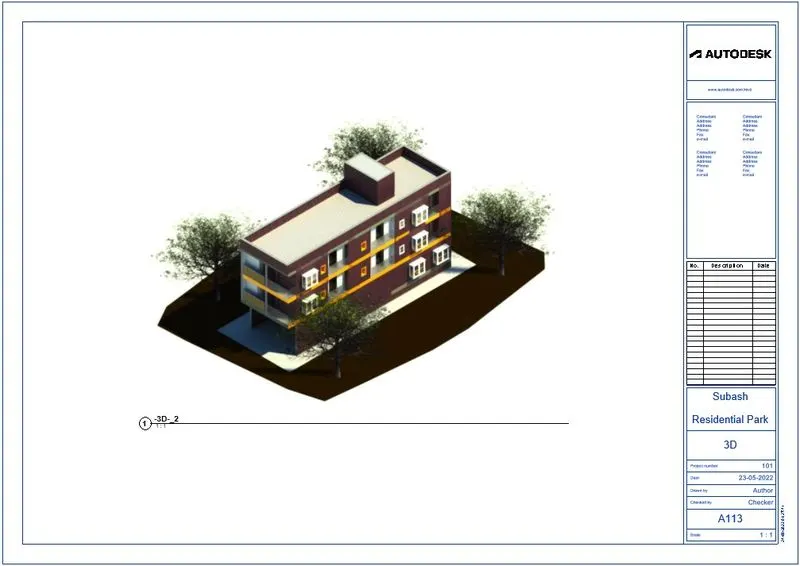
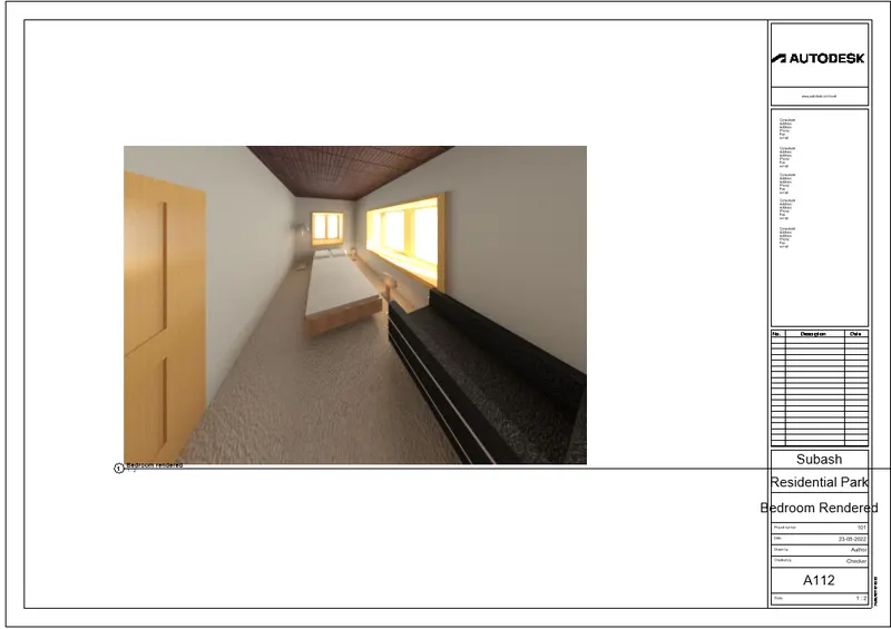
Result:
Rendered could be done by using Revit software. Following sheets are having rendered images in it.
7) Print the set of drawing sheets created and submit the drawings from the architecture and structure model
Aim: To print the drawing sheets from architectural and structural models by using Revit software
Procedure:
step-1: Go to file
step-2: Select print option
step-3: Or Press CTRL+P

step-4: New dialogue box will open
step-5: Select the foldre required to save the file
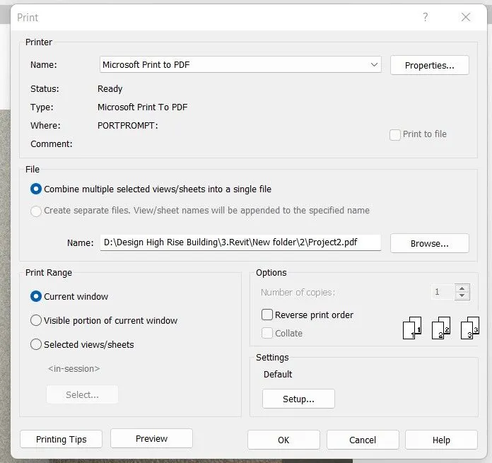
step-6: Select microsoft print to pdf
step-7: Choose the folder
step-8: Renamed it and then click ok to save pdf file
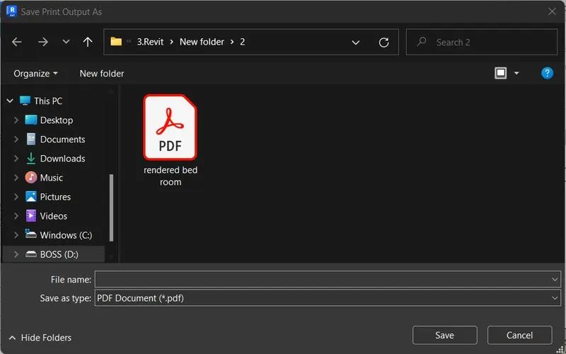
step-9: Like the above steps we did some file to save as a pdf.
step-10: Following images are saved like this.
structural template model:
Architectural template model sheets:
Result:
Print option can be done by Revit software and also included some drawing sheets from structural and architectural model file.