Creating Architectural and Structural model with 3D rendering using REVIT
INTRODUCTION: The main aim of this whole challenge is to create a project file of any desired type from school, residential, or office buildings. The students need to create whole a structural file, an architectural file, and a construction file of the whole project. This whole project will include all the things which were taught up to the 7 weeks. Please have a look at each question and its respective procedure and results for more clarity. Please note that the snips for each question are attached at the end, i.e., after the procedure and result of each question!
AIM_1: Select the type of structure you want to build from one of the three below:
a. Multi-Unit Residential Apartment
b. Office Buildings
c. School
ANSWER: I am selecting an office building as n option for my project 2.
AIM_2: Assume reasonable assumptions for geographic and location details for your project modeling. Based on assumptions and type of structure selected identify the modeling requirements from NBC
ANSWER:
- I have assumed a plot size of 200' x 180' for the construction of the building.
- It is a plot situated in a very prime location of Ahmedabad city of Gujarat, India.
- The width of the street on one side of the plot is 60m and on the other side, the width is 40m.
- Now the modeling requirements from the NBC for Commercial building can be given as follows:
- The building comes under the type-2 building construction type.
- The plot area is 36000sqft, which is equal to 4000sqyrd.
- The maximum permissible height of the building will be 1.5 times the width of the street near it. In the case of two streets, take the value of higher width. Therefore the permissible height of the building is 90m.
- The FSI at that location of Ahmedabad is 4.0, so we can construct a total area of up to 16000sqyrd.
AIM_3: Using the structural model, include the following components based on the type of structure selected
a. Foundation – Isolated / Wall/Matt Foundation
b. Columns
c. Beams Connected to Columns
d. Roof Framing/ Truss
e. Floor / Decks
f. Floor Openings for Elevators and Stairs
PROCEDURE:
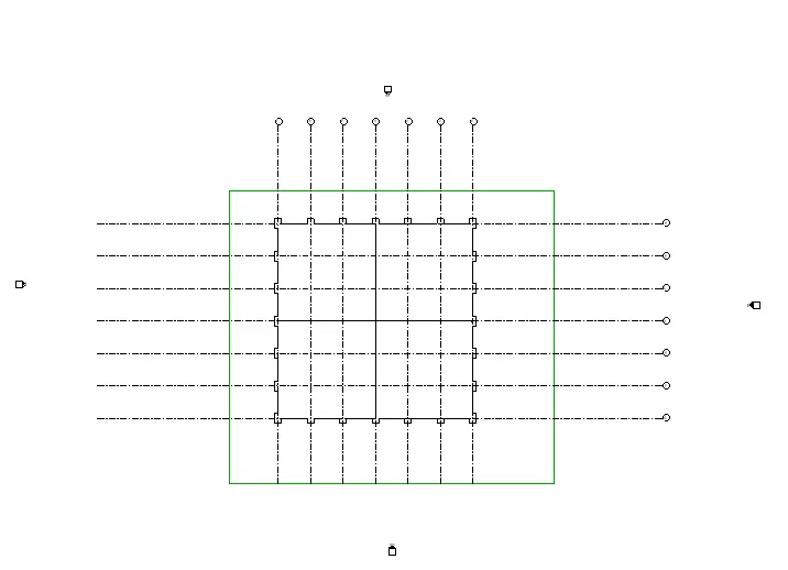
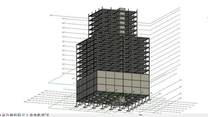
- Go to the structural file.
- Create the grids as per your designs.
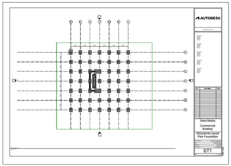
- Start with creating foundations on the grids.
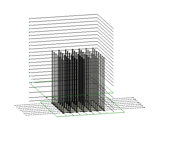
- Then create levels, till the maximum height of the building.
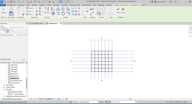
- Then create the columns and beams on the foundation, using the commands given in STRUCTURAL TAB only.
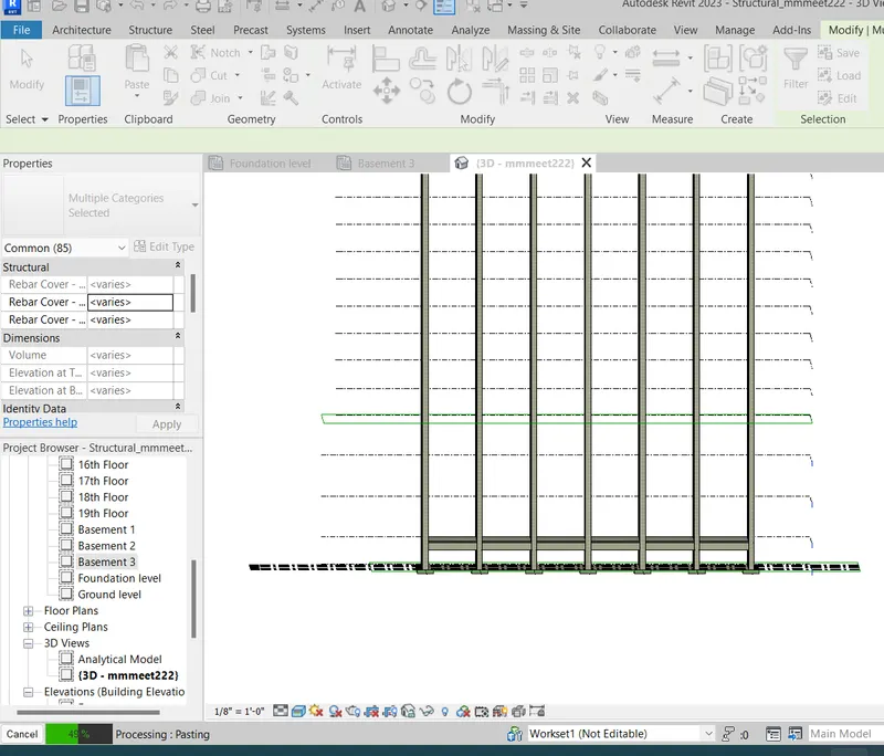
- Then copy the beam and column using a paste to the aligned levels as per your design.
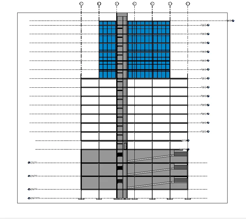
- Then create the shaft for lifts and stairs.
- Then in the architectural menu, select ramp and create the ramps for the basement of the building.
- Please have a look at the below snips for more clarity.
RESULT: The structural frame of the building is ready.
SNIP:
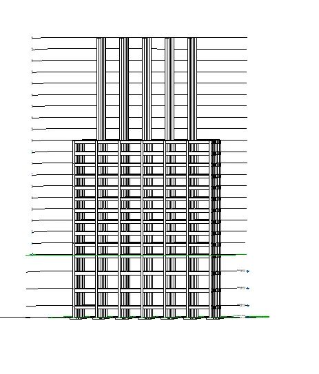
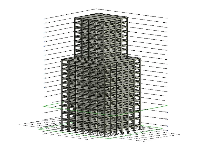
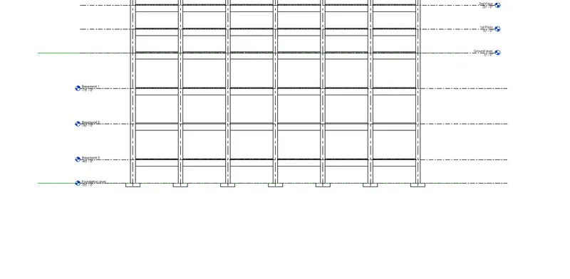
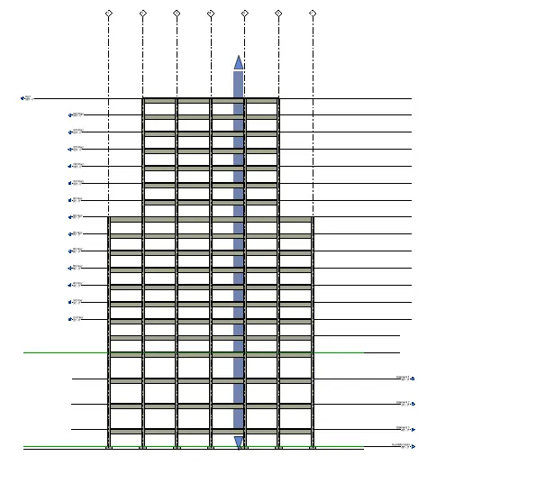
AIM_4: Using the architectural model, include the following components based on the type of structure selected
a. Wall Layout with appropriate material and finishing
b. Exterior façade with fancy finish
c. Interior partition walls to size rooms
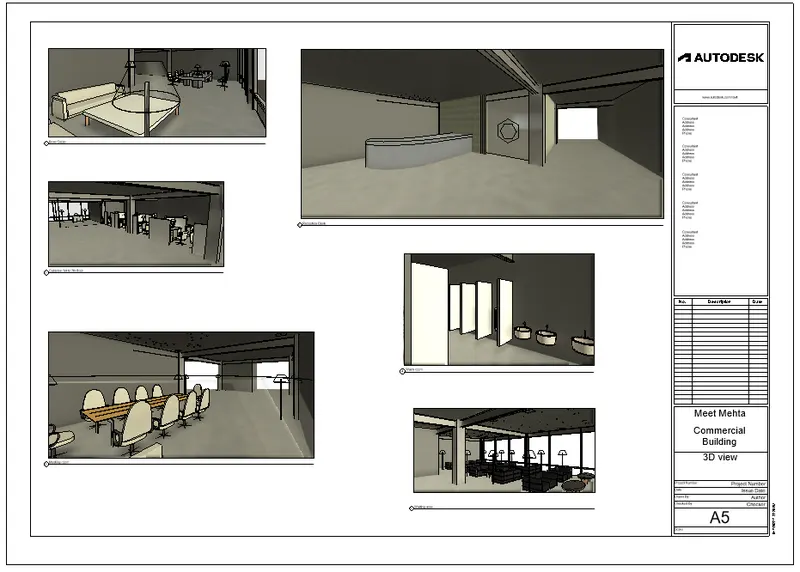
d. Components to add details to a room ( Desk, Chair, Lighting, Plumbing fixtures)
e. Add components such as stairs Elevators
f. Have at least one side of the building with curtain walls and glass panels
g. Include interior and exterior lighting fixtures
h. Place proper topographic components from outside ( Trees, Parking, Plants) to add details to the model
PROCEDURE:
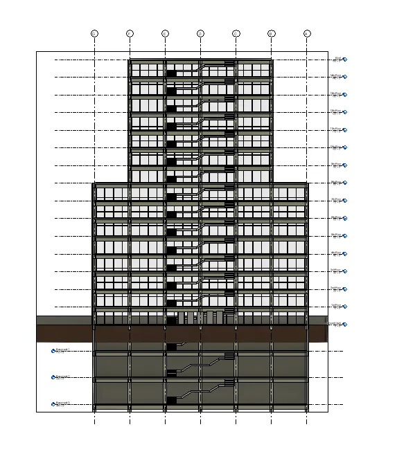
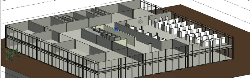
- Now go to the architectural file and then load the structural file.
- Copy/monitor the link and then start designing the building.
- Create the partitions of the building.
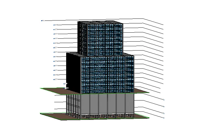
- Add exterior facade.
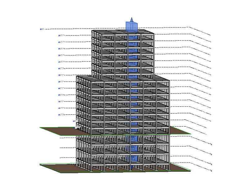
- Then start adding components to define the building.
- Components like chairs, tables, lights, etc were added.
- Add the lighting fixtures.
- Please have a look at the below snips for more clarity.
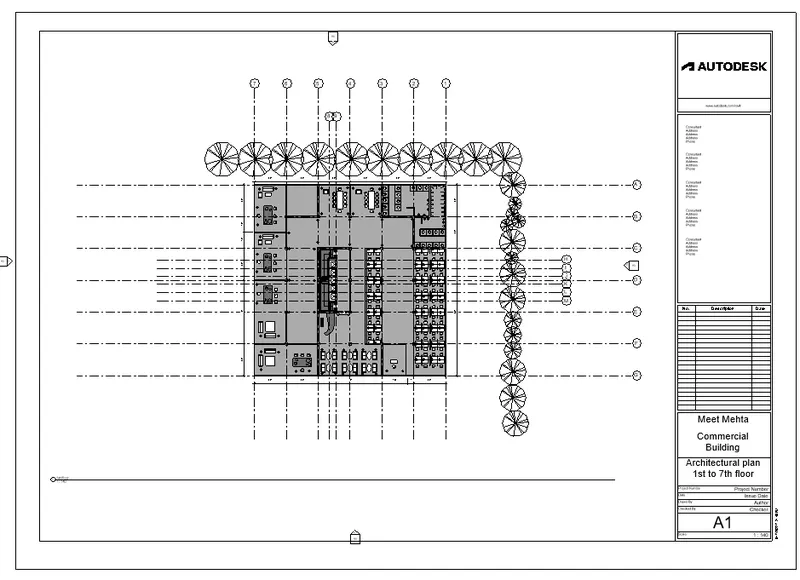
RESULT: The architectural part of the building is created.
SNIP:
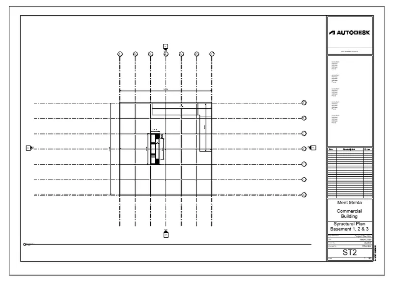
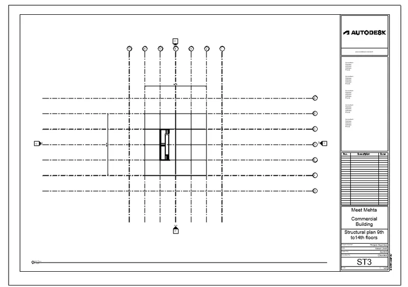
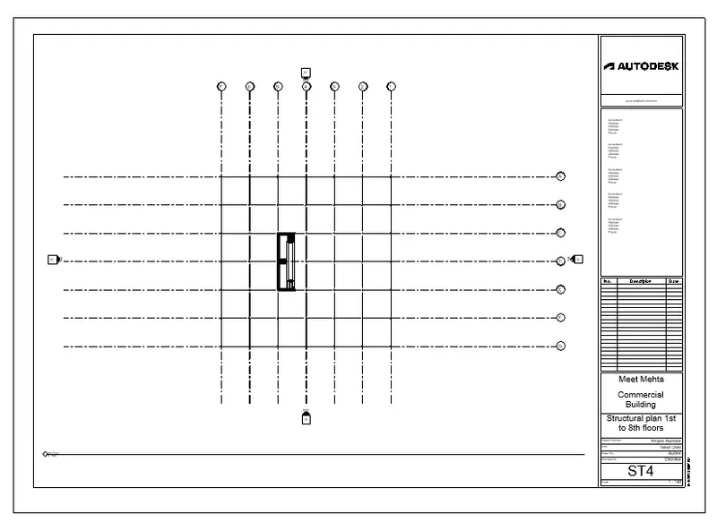
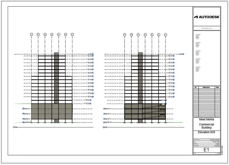
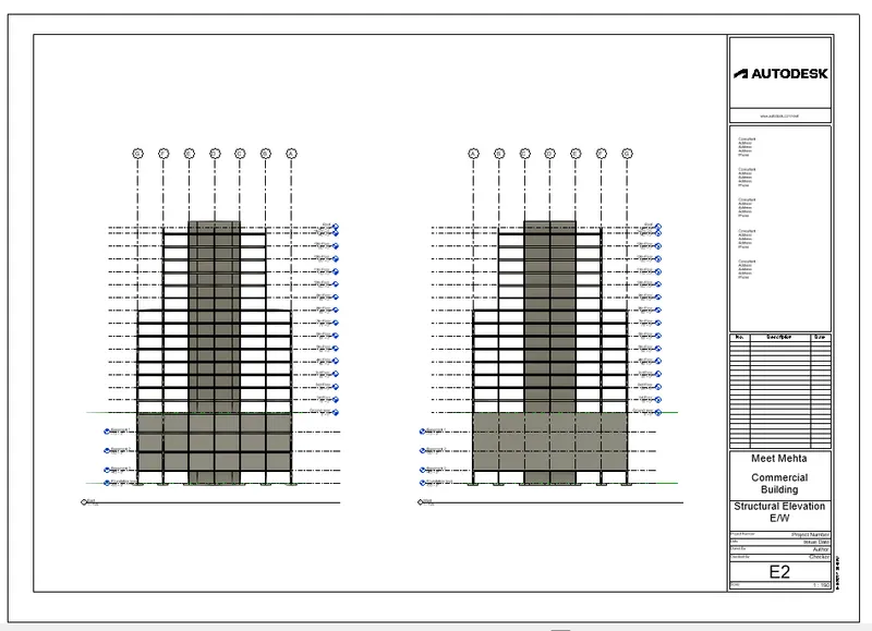
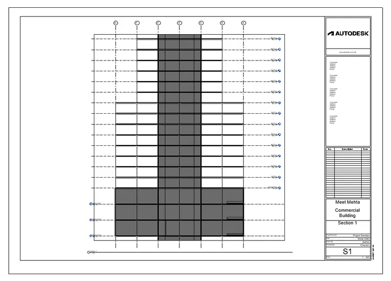
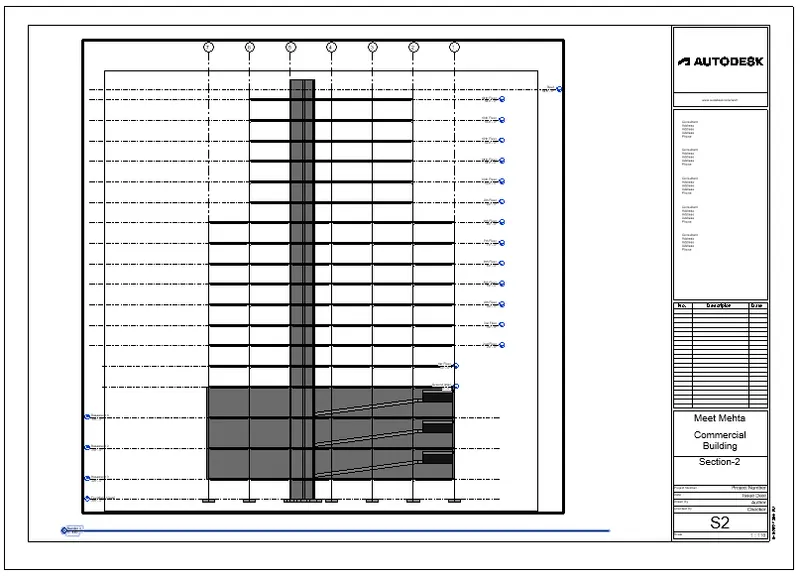
AIM_5: Provide a set of drawings in an architectural and structural model to list the following details with categories and appropriate sheet templates included
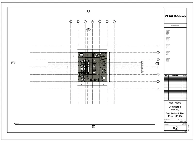
a. Floor Plans with Annotations
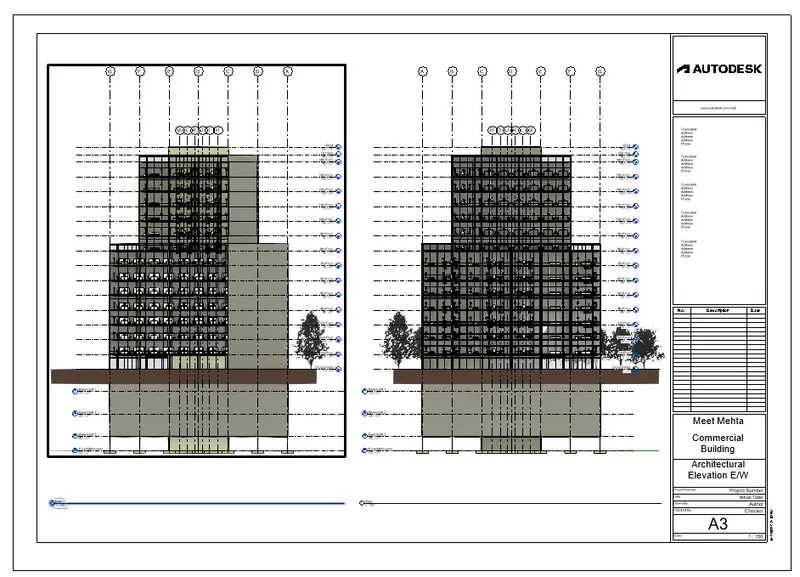
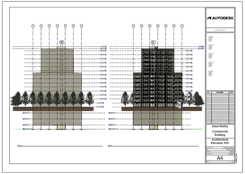
b. Elevations
c. Sections
PROCEDURE:
- Now once all the floors are planned, create the sheets.
- Go to the view menu and select sheets.
- Name it as you like.
- Drag the views or plan you like to add and scale it.
- Add 3D views, structural plans, foundation plans, floor plans, etc for the whole building.
- Please have a look at the below sheets for more clarity.
RESULT: The sheets were created.
SNIP:
Architectural Snips:
Structural snips:
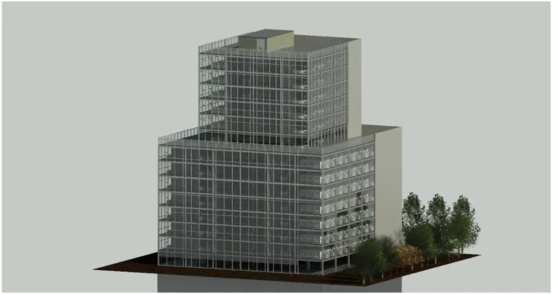
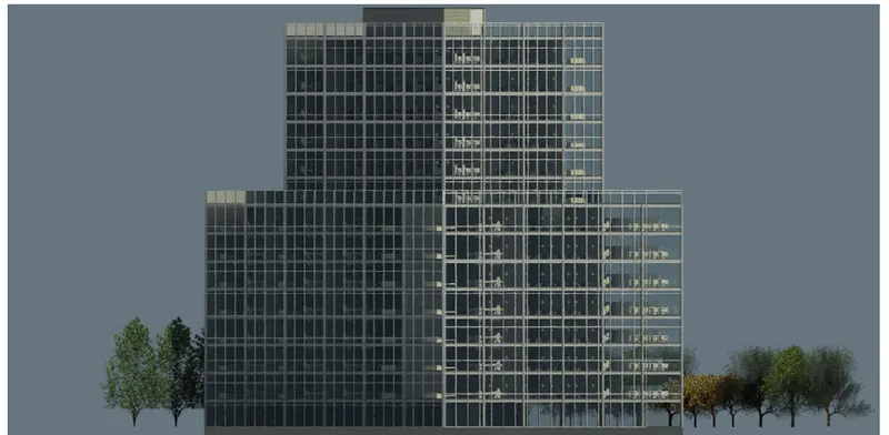
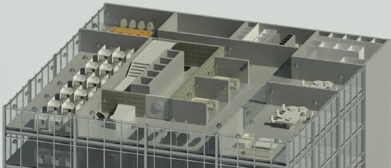
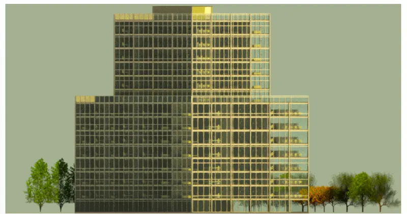
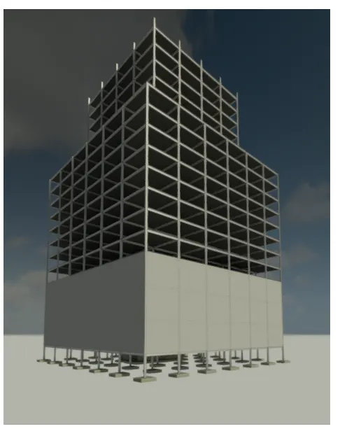
AIM_6: Using the Rendering settings, Render images of the 3D model produced and include the rendered images in the drawing sheets
a. Rendering from interior rooms
b. Rendering from out showing topographic features
c. Rendering through structural framing
PROCEDURE:
- Once everything is done, now comes the turn of rendering.
- Go to the view menu and click on the render.
- Define the settings of quality, lighting, etc, and then click render.
- Create render of different views for giving the best clarity to the clients.
- The below are the renders given, please have a look at them for better clarity.
RESULT:
SNIP:
AIM_7: Print the set of drawing sheets created and submit the drawings from the architecture and structure model
PROCEDURE:
- Once the whole project is done, the sheets are printed.
- Click open the sheet, and then click CTRL + P on the keyboard.
- Select the option for all the sheets.
- Select the option as Microsoft to pdf in the printer section.
- Then click ok
- The pdf is created.
- Please have a look at the attached pdf for more clarity.
RESULT: The printout can be handed by printing out the PDF.