Creating Architectural and Structural model with 3D rendering using REVIT
AIM & INTRODUCTION :
AIM:
To create and render both the Architectural and Structural model of a Office building in revit and make sheets with the rendered files.
INTRODUCTION :
- Here in revit we can create models in both architectural and structural.
- The architectural model includes walls. floors, roofs, doors, windows etc.
- The structural model includes Columns, beams, footings, structural floors etc.
- The created model the can be rendered using the render tool.
- The sheet template can also be created and the rendered view could be attached into it.
PROCEDURE :
- Open a new construction template from the File tab < New <Project< construction template.
- Then create a levels such as footing level, ground floor level, first floor level, second floor level and roof level from Architecture < levels.
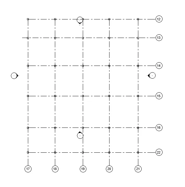
- Create gridlines on all the levels, where the structural components are needs to be attached at its intersectional points.
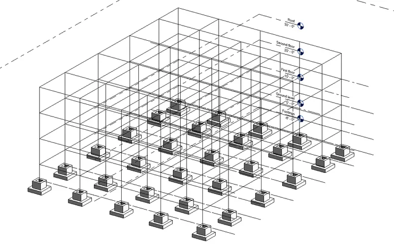
- Then create the footings from the Structure tab < Footing (Foundations) < at the grids and place it at the footing level by selecting all the grids created.
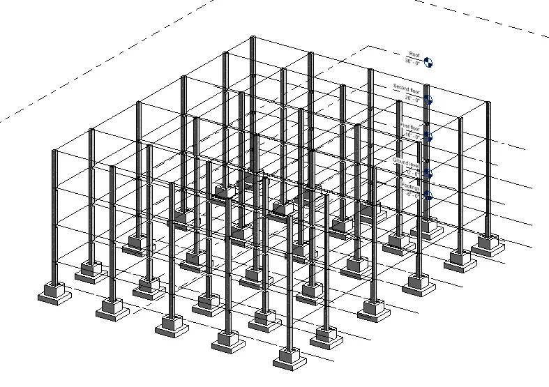
- Create columns vertically from Structure tab < columns < at the grids and and change the "base level" and "top level" from ground level to roof level.
- Likewise the Beams should be created at the grids horizontally by selecting all the grids, and this should be followed upto roof level.
- Then the Structural floor has to be created over the beams which were created at the appropriate level from Structural tab < floor.
- After creating the structural elements, the Architectural elements are then needs to be created such as walls, curtain walls, staircase, furnitures etc.
- The walls are placed all around the created structure model from the Architecture tab < walls .
- Then the front elevation walls are changed into a curtain wall with grazing wall finishing by editing its properties in the properties tab.
- Likewise the partition walls can also be placed inside the building by changing appropriate thickness such as 4" wall.
- The Staircase and the elvators are then created from ground floor to upto the Second floor level.
- Before placing the staircase and the elvators, the shaft opening has to be created at the approprite place where the staricase and the elvators are needs to be provided.
- The shaft opening will be created over the floors from ground level to the second floor level from the Architectural tab < Shat opening.
- Then the appropriate staircase and th elevators are need to be provided.
- Then the furniture elements are needs to be provided from the Architecture tab < Components < Place a component < load family select appropriate families to place it on appropriate place.
- The topo surface is then created below the ground level and the topographic features are then created over it such as trees, plants and vehicles etc.
- After creating all the required elements into the created model, the rooms, elevations, architectural and Structural elements are needs to be rendered using render option.
- The render option is evoked from the View tab < render.
- Then the rendered view are then placed into the sheets and the sheets are needs to be saved as pdf to submit.
- The sheets are created from the View tab < sheet.
RESULT :
1. The type of builing is to be build :
a.) OFFICE BUILDING
2. Reasonable assumptions for geographic and location details for project modeling :
- The open space around the building shall not be less than 4.5 meter.
- The type of constructions as type 2 of construction, the FAR value of the buisiness building shall be taken as 2.9
- The plot size is taken as 40m x 70m i.e, 2800m2 and individual floor plan area is 2000m2. Hence FAR value obtained is 2.14 which is within the prescribed limits as per NBC.
- The width of the road abutting the building is taken as 9m.
3. Using the structural model, include the following components :
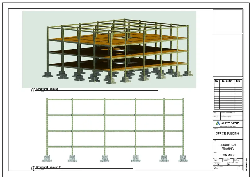
a. Foundation – Isolated Foundation :
b. Columns :
c. ) Beams connected to columns :
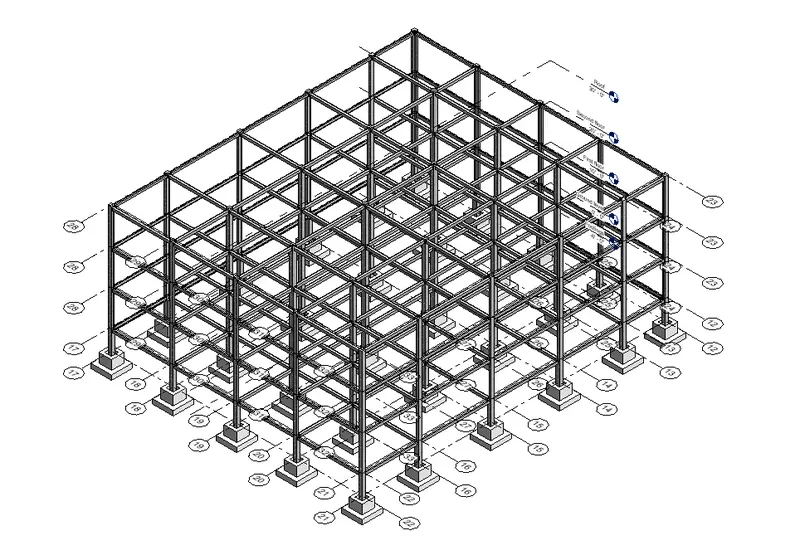
d. ) Roof framing :
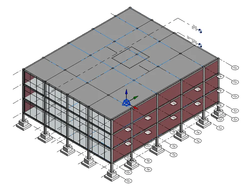
e. ) Floors :
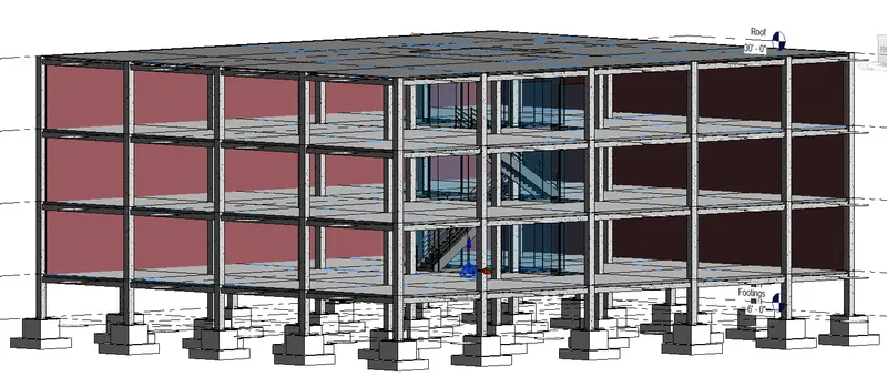
f. ) Floor openings for elevators and stairs :
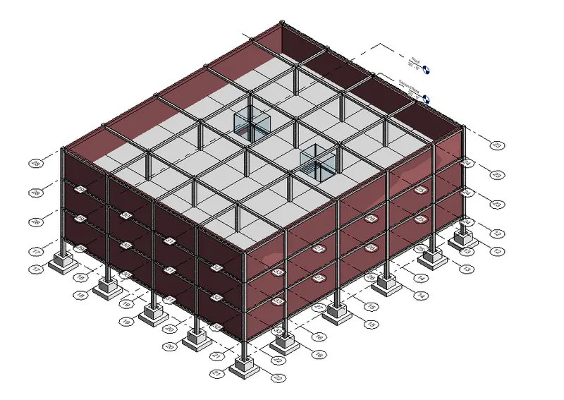
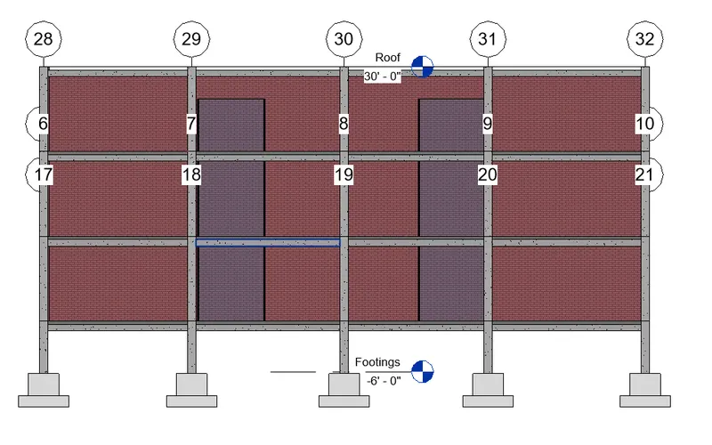
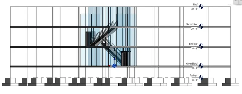
4. the architectural model, include the following components :
a. ) Wall Layout with appropriate material and finishing :
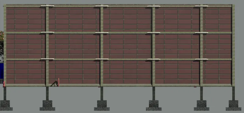
b. ) Exterior façade with fancy finish:
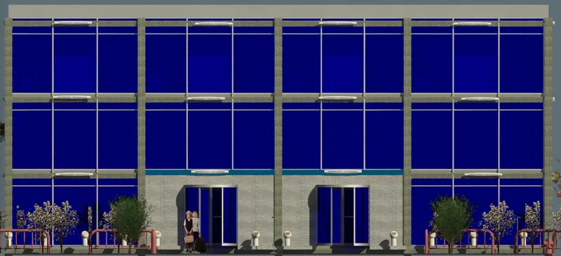
c. ) Interior partition walls to size rooms :
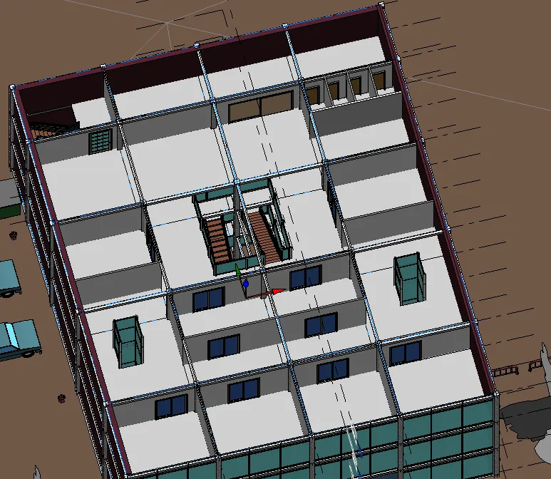
d. ) Components to add details to a room ( Desk, Chair, Lighting, Plumbing fixtures) :
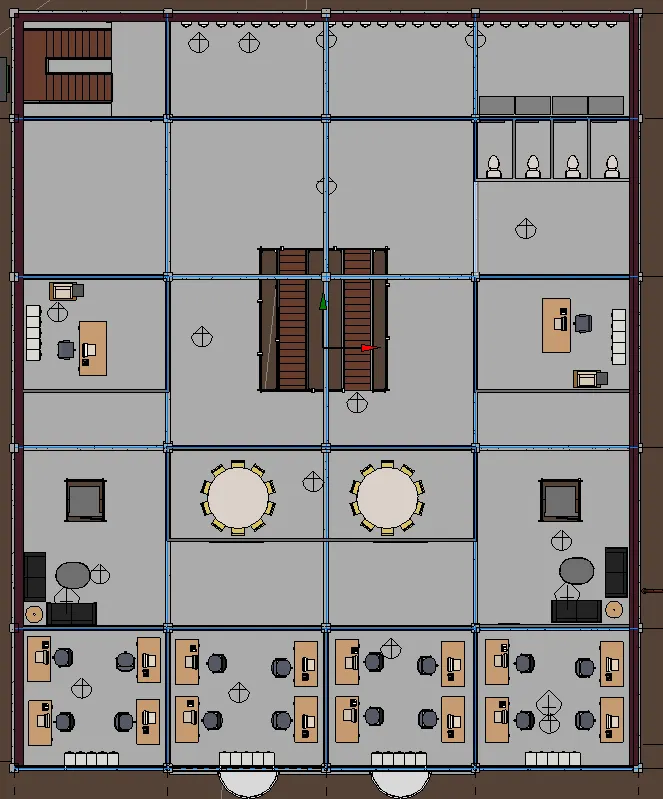
e. ) Add components such as stairs Elevators :
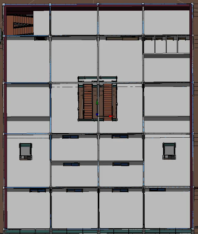
f. ) Have at-least one side of the building with curtain walls and glass panels :
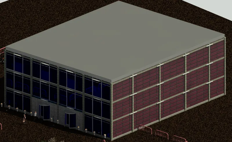
g. ) Include interior and exterior lighting fixtures :
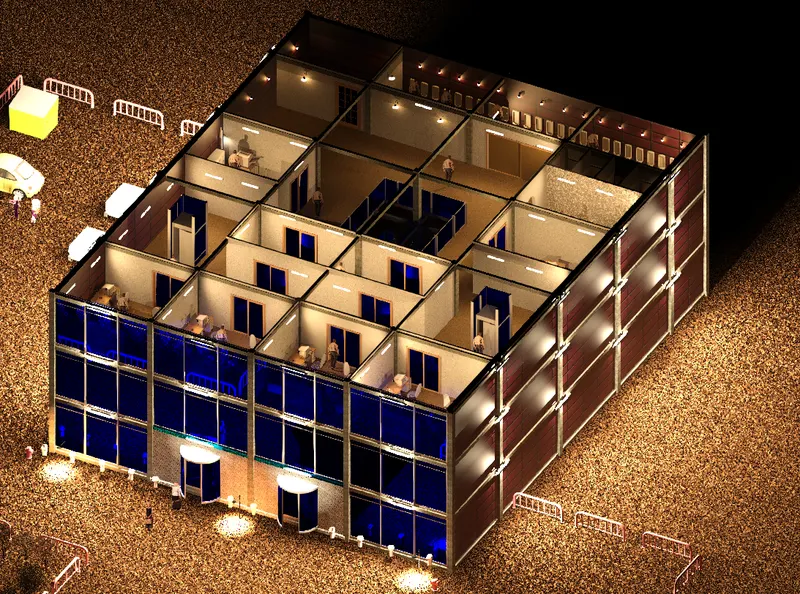
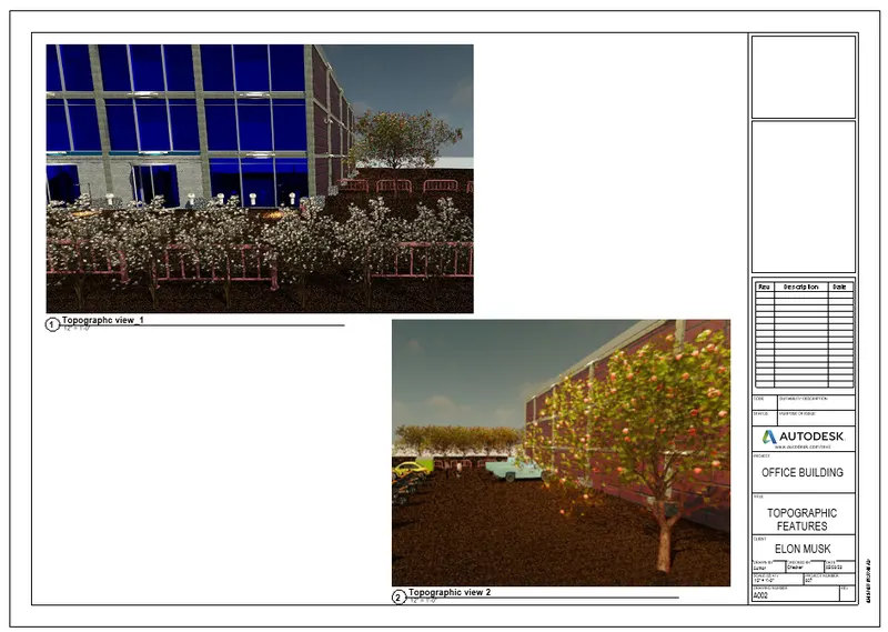
h. ) Place proper topographic components from outside ( Trees, Parking, Plants) to add details to the model :
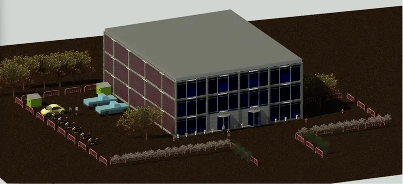
5. Set of drawings in an architectural and structural model :
a. ) Floor Plans with Annotations :
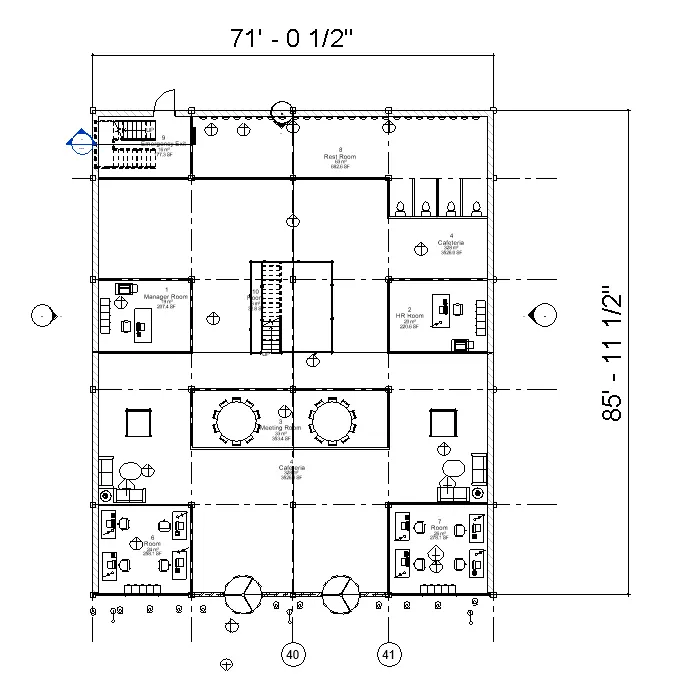
GROUND FLOOR PLAN
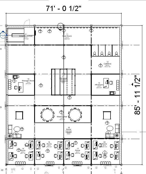
FIRST FLOOR PLAN
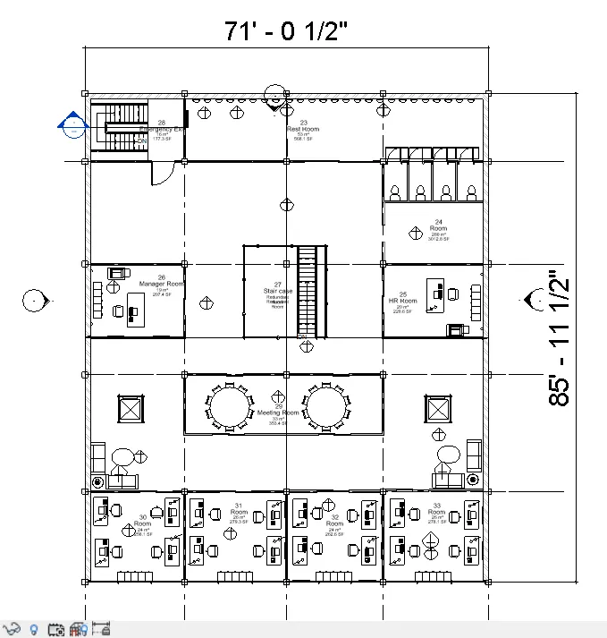
SECOND FLOOR PLAN
b. ) Elevations :
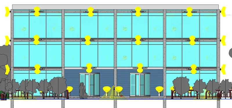
SOUTH ELEVATION VIEW
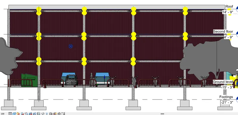
WEST ELEVATION VIEW
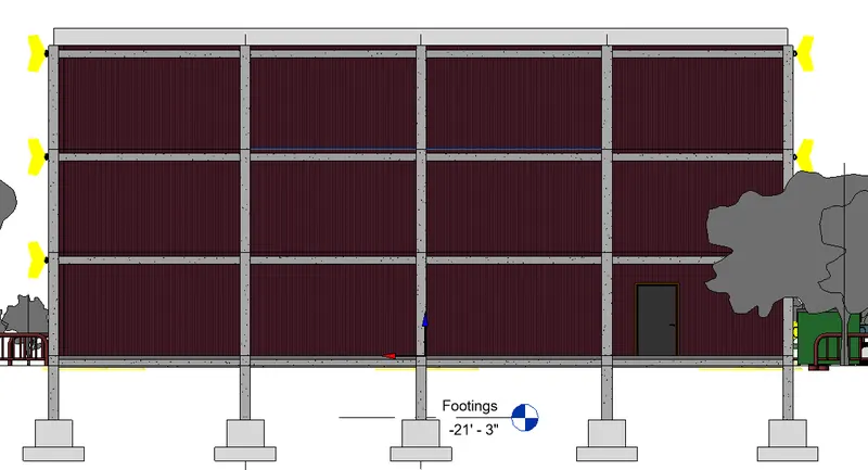
NORTH ELEVATION VIEW
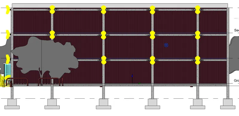
EAST ELEVATION VIEW
c. ) Sections :
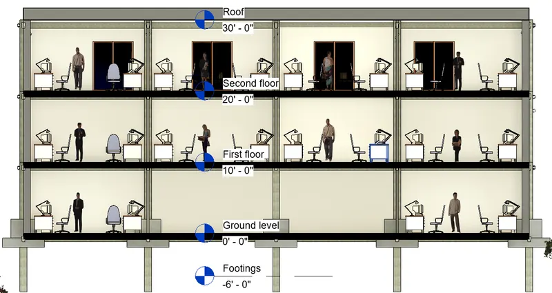
WORKING ROOMS SECTIONAL VIEW
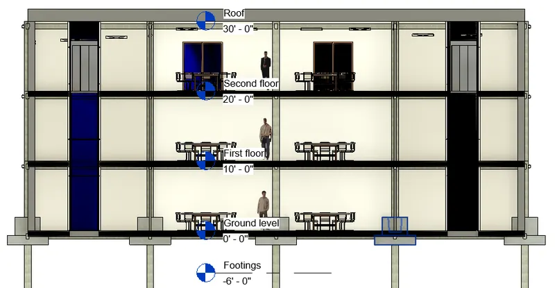
MEETING ROOM SECTIONAL VIEW
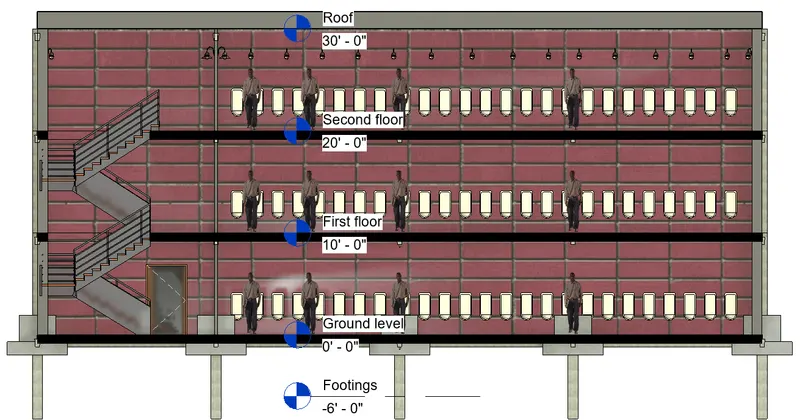
REST ROOM SECTIONAL VIEW
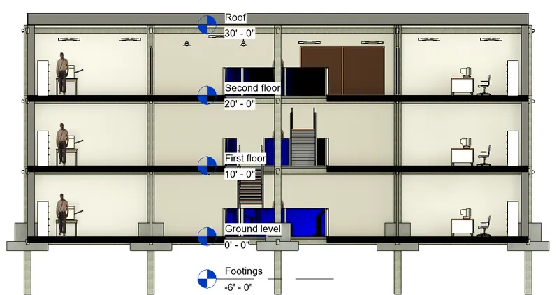
HR ROOM AND MANAGER ROOM SECTIONAL VIEW
6. Using the Rendering settings, Render images of the 3D model produced and include the rendered images to the drawing sheets :
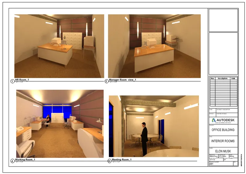
a. ) Rendering from interior rooms :
b. ) Rendering from out showing topographic features :
c. )_ Rendering through structural framing :
7. The set of drawing sheets created and the drawings from the architecture and structure model are attached into it and submitted.