Creating Architectural and Structural model with 3D rendering using REVIT
Creating Architectural and Structural model with 3D rendering using REVIT
1) Select the type of structure you want to build from one of the three below:
a. Multi-Unit Residential Apartment
b. Office Buildings
c. School.
Answer: I have Choosen to Design an Office Building.
--------------------------------------------------------------------------------------------------------------------------------------------
2) Assume reasonable assumptions for geographic and location details for your project modeling. Based on assumptions and type of structure selected identify the modeling requirements from NBC.
Answer:
- The Assumed Location for my Project is Guwahati,Assam.
- Building is Constructed as Type 2 Construction.
The Modelling Requirements for the Pffice Building as per NBC are as follows:
- The Open Spaces around the Building Should not be Less than 4.5m.
- The Width of means of access is taken to be 12m.
- The Floor Area Ratio (FAR) for Type 2 Construction Business Building Shall be 2.9.
- In my Project the Plot Size is 60mx50m which is equal to 3000m2, and the area of each is 1920m2, Therefore the FAR Comes out to be 1.92[(1920*3)/3000],which is less than 2.9 and within the limits provided by NBC.
FAR = (Total Covered area of all Floors)/Plot Area.
-------------------------------------------------------------------------------------------------------------------------------------------
3) Using the structural model, include the following components based on the type of structure selected
a. Foundation – Isolated / Wall/Matt Foundation
b. Columns
c. Beams Connected to Columns
d. Roof Framing/ Truss
e. Floor / Decks
f. Floor Openings for Elevators and Stairs.
AIM: To Create the Structural Model of the Office Building.
Introduction: The Procedure of creating the structural model of the office building is explained in detail and the final result is given.
Procedure:
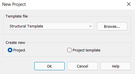
- In the New project dialog box, Select the Structural template from the drop down list.
- Create New> project>Ok.
- Next Click on the File Tab.
- Click on Save as Option >Project.
- Specify the location Where You want to Save the File.
- Enter the File Name OfficeBuilding_Structural>Save.
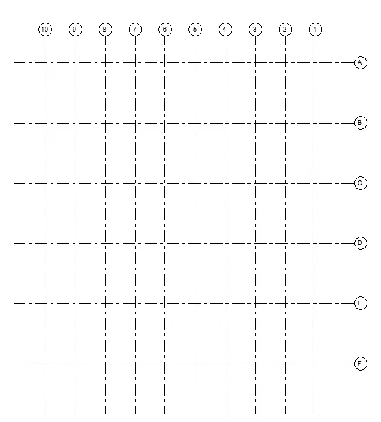
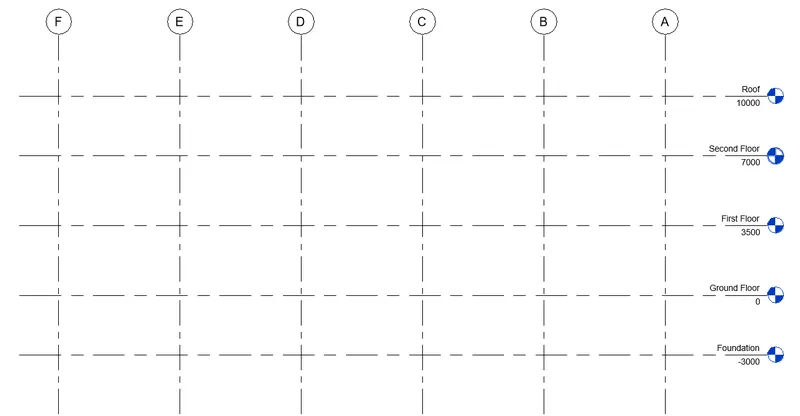
- Create the Grids and Levels for the Project.
- Go to Project browser >Structural plans>Foundation.
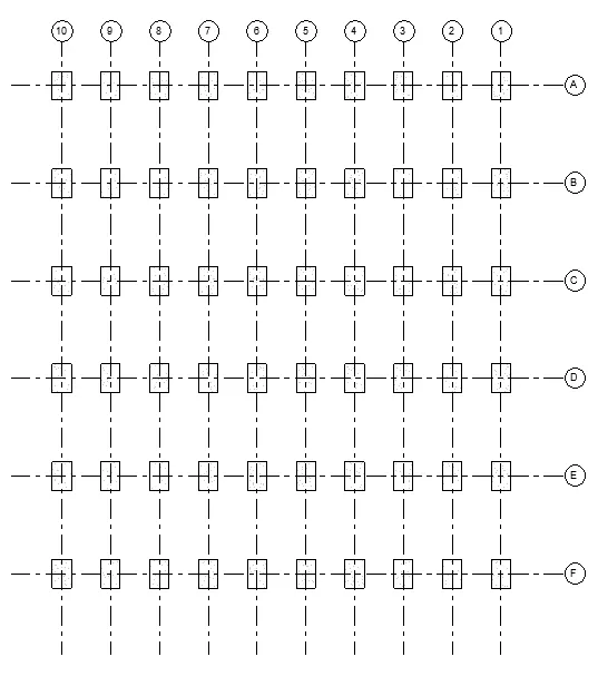
- Structure tab> Foundation >Isolated.
- Select the At Grids option.
- Select all the Longitudnal and Transverse grids>Finish>Esc.
- View>3D View> Default 3D View.
- To add Columns, Go to Project Browser>Structural Plans>Ground Floor.
- Structure Tab>Column.
- Select the type and size of the column from properties browser.
- Select at grids option>Select all grids>Finish.
- View>3D View.
- To Extend the Columns to the Second Floor level, go to ground Floor Plan View.
- Select all the Columns.
- Go to the properties window.
- Change the top Constraint to Roof>Apply.
- To add beams, Go to Project browser > Structural plans > Ground Floor.
- Structure tab> Beam.
- Select the type and size of beam from properties browser.
- Select on Grid option> Select all Grids >Finish.
- Similarly create beams for first and second floor levels.
- To add beams, Go to project browser>Structural plans> Ground Floor.
- Structure tab> Floor.
- Select the type and size of the floor from properties browser.
- Select rectangle option> Draw the Floor in the Shape of the Rectangle>Finish.
- Similarly create Floor for first and second floor levels.
- To add truss.Structure tab >truss.
- Select the type and size of the truss from properties browser.
- Select pick line option.
- Pick lines as Suitable>Finish.
- To Create Opening.
- Structure tab >Shaft.
- Select rectangle option.
- Draw a rectangle of Suitable size>Finish.
- Collaborate and the Save the Structural model as a Central File.
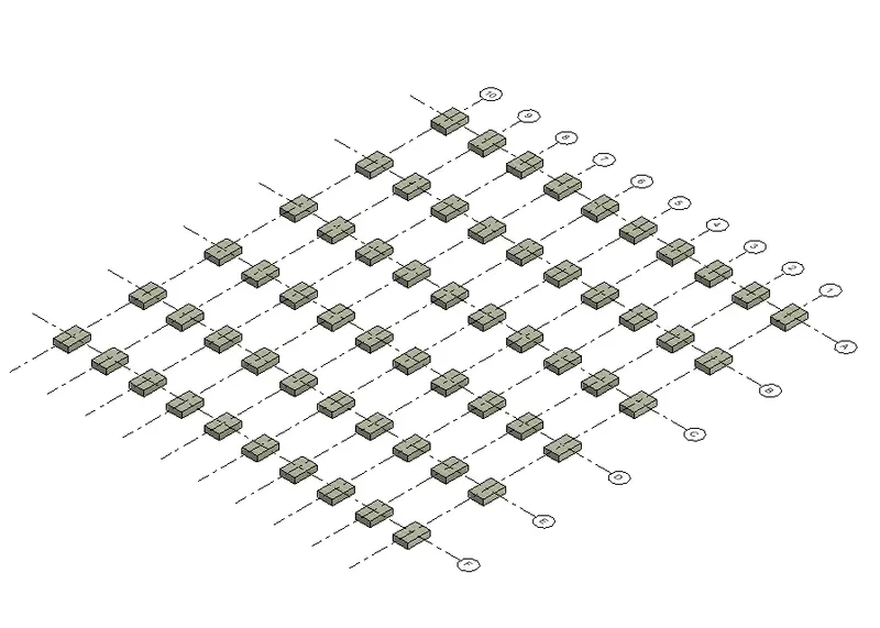
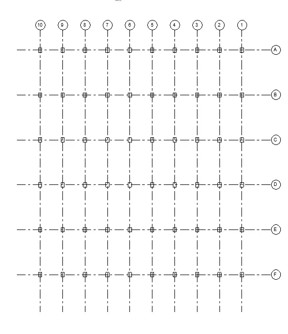
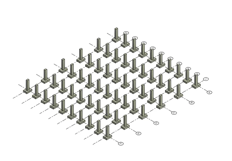
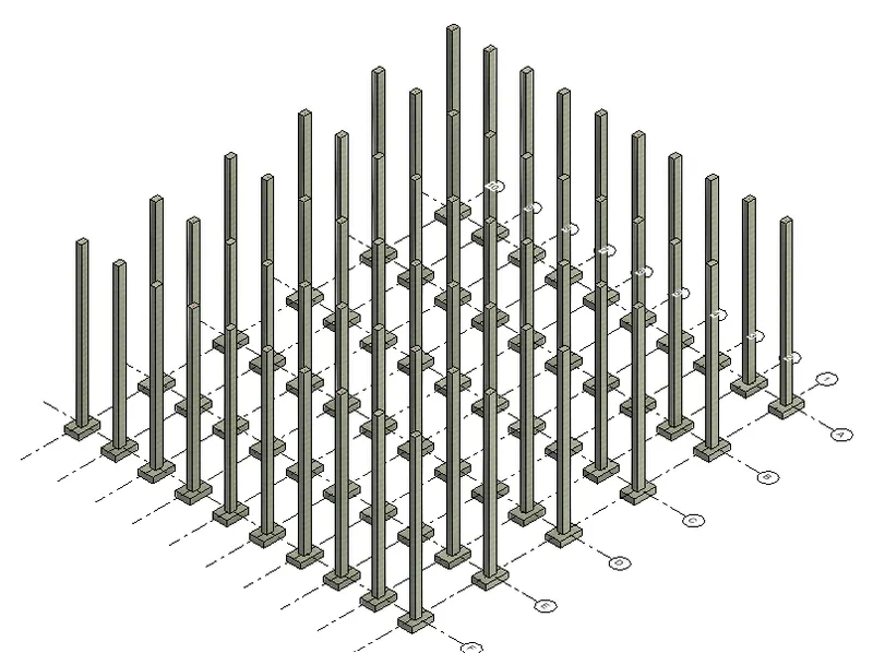
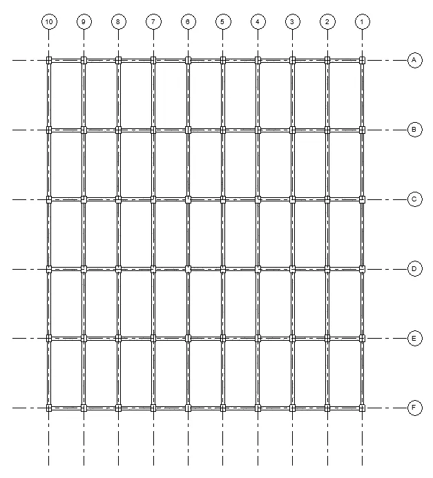
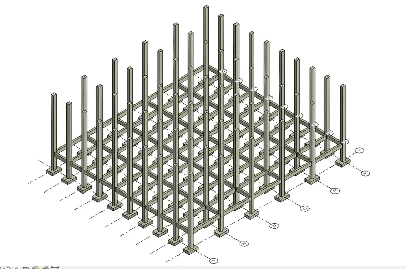
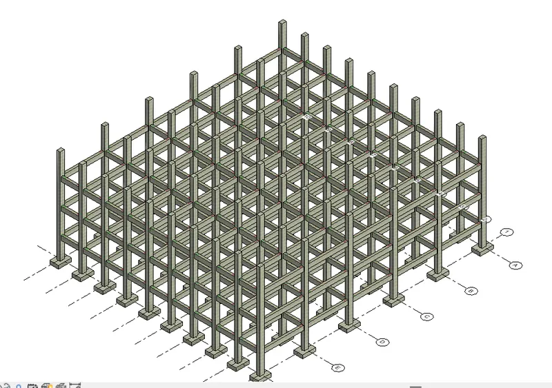
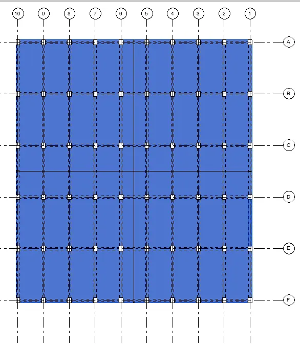
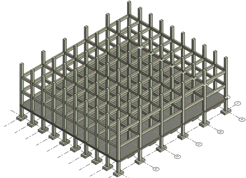
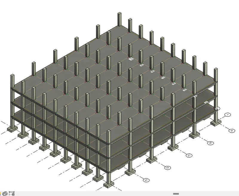
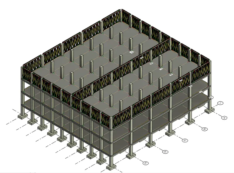
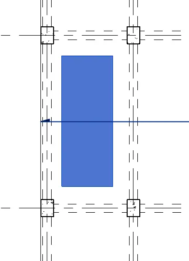
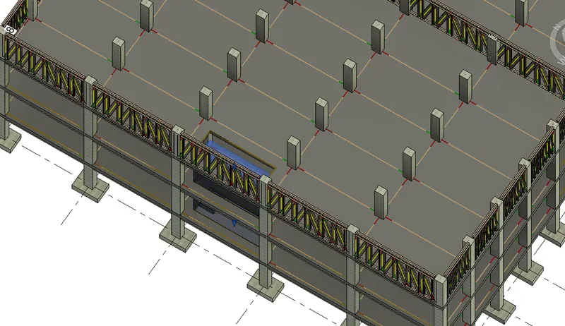
Result:
A structural model of an office Building has been created.The Procedure to create structural components including- Foundation, Columns, Beams, Roof truss, Floor, and Shaft opening has been Clearly illustrated.
-------------------------------------------------------------------------------------------------------------------------------------------
4) Using the architectural model, include the following components based on the type of structure selected
a. Wall Layout with appropriate material and finishing
b. Exterior façade with fancy finish
c. Interior partition walls to size rooms
d. Components to add details to a room ( Desk, Chair, Lighting, Plumbing fixtures)
e. Add components such as stairs Elevators
f. Have at-least one side of the building with curtain walls and glass panels
g. Include interior and exterior lighting fixtures
h. Place proper topographic components from outside ( Trees, Parking, Plants) to add details to the model.
AIM: To Create the Architectural Model of the Office Building.
Introduction: The Procedure of creating the Architectural model of the office building is explained in detail and the final result is given.
Procedure:
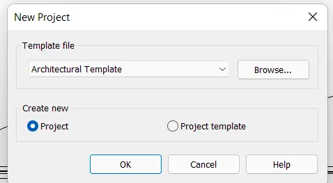
- In the New project dialog box, Select the Architectural template from the drop down list.
- Create New> project>Ok.
- Next Click on the File Tab.
- Click on Save as Option >Project.
- Specify the location Where You want to Save the File.
- Enter the File Name OfficeBuilding_Architectural>Save.
- Go to Manage>Manage Links,Click on add in the Manage Links dialog box.
- Select the Office Building_Structural> Open>Ok.
- Go to Collaborate >Copy/Moniter >Select Link.
- Select the Link of the Office Building Structural Model.
- Select the Copy Option.
- Select the Entire Model.
- Click Finish.
- Enter VG.
- Go to Revit Links>Hide Visibility of the linked Structural Model.
- Project Browser> Ceiling Floors> Second Floor.
- Select the Ceiling Tool by going to Architecture> Ceiling>Sketch Ceiling.
- Select the pick line option from the draw panel.
- Select the outer edges in the Second Floor Plan.
- Click on the Finish edit mode icon.
- The Ceiling has been created.
- Project browser> Floor Plans> Ground Floor.
- Select the Ceiling Tool by going to Architecture>Floors> Architectural Floor.
- Select the rectangle option from the draw panel.
- Draw the floor around the building and provide suitable offset to it.
- Click on finish edit mode icon.
- Project browser>Floor plans>Roof.
- Select the Roof Tool by going to Architecture tab> Roof >Roof by Footprint.
- Select the base level as roof level.
- Select the pick line option from the draw panel.
- Select the outer edges of the top of the second floor ceiling.
- Go to Properties >Dimensions>Slope.
- Enter Slope Value as 10>Apply.
- We can edit footprint to extend the edges of the roof.
- Click on the Finish Edit mode icon.
- The Roof is Created>save the Project File.
- Project Browser>Floor plans>First Floor.
- Select the roof tool by going to Architecture>wall>Architectural Wall.
- Select the suitable types of the wall.
- Create the internal and external walls of the building.
- Front exterior of the wall is created using Glass Curtain Wall.
- Project browser floor plans ground floor.
- Select the roof tool by going to Architecture>Door.
- Select the Curtain wall door type and add it to the Suitable locations at the Enterance of the building.
- Project Browser>Floor plans> Ground Floor.
- Go to Architecture> Stairs.
- Select the Run and then choose straight.
- Draw the Staircase as per the floor opening created earlier.
- Click on the finish edit mode icon.
- Go to Architectural railing.
- Draw railings around the floor opening as required.
- Click on the Finish Edit Mode icon.
- Go to Insert>Load Family Option (Go to Architecture>Component>Load Family).
- In the Load Family Dialog Box Browse to laibraries.
- Next go to US>Window.
- Select the Desired type of Window>Open.
- Again Reapeat the above process to load other elements such as furniture,Lighting, Plants Etc.
- Then go to Project Browser>Families.
- Select the Desired Components and drag and add them to the Model.
- Go to Architecture>Room.
- When dragged to the project space it automatically Selects the rooms based on the layout boundary.
- Using the room tool Create all Specify all the rooms in the layout>Save the File.
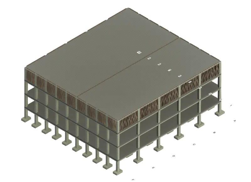
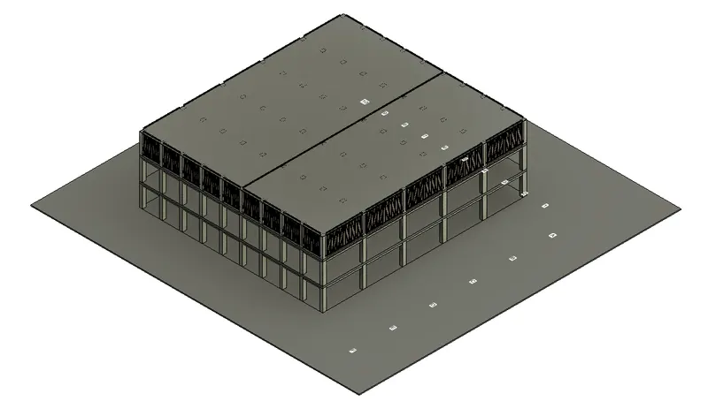
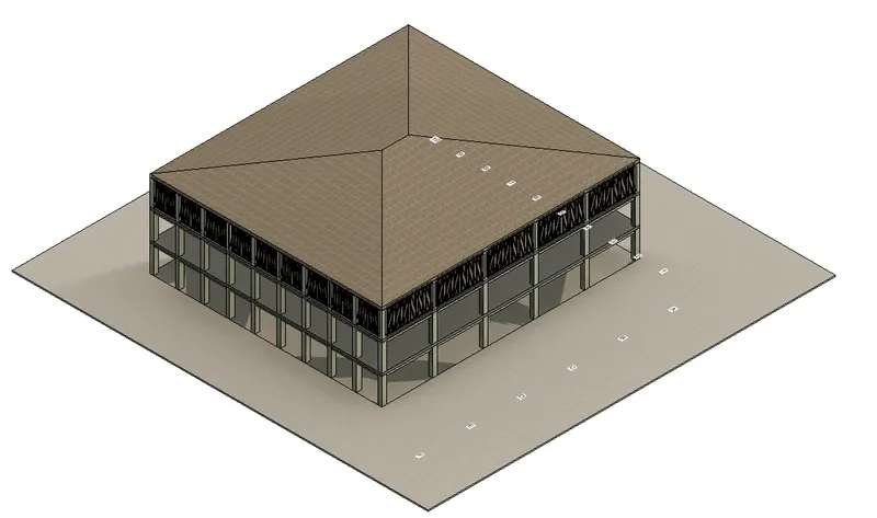
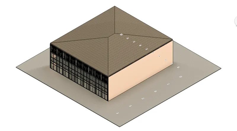
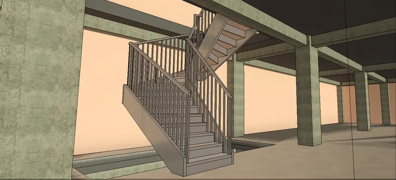
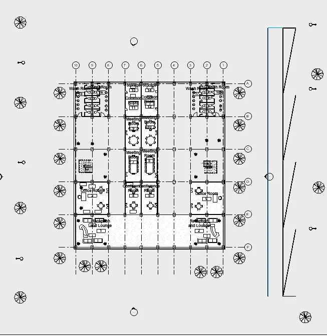
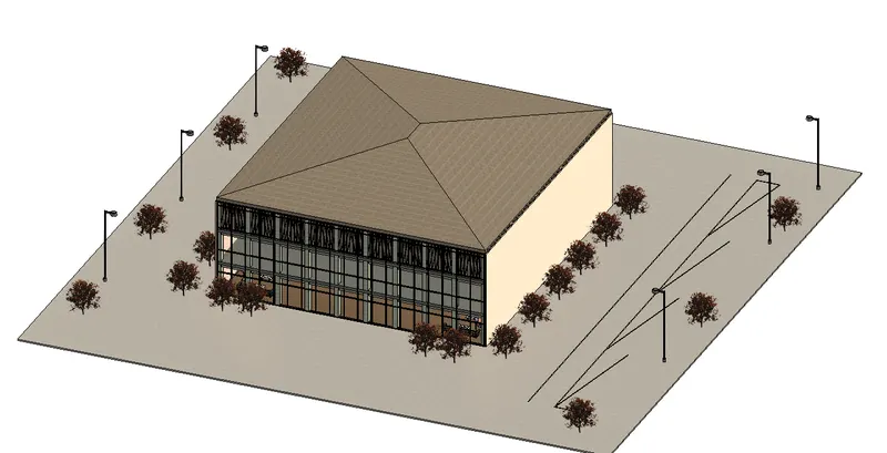
Result:
The Architectural Model of the office building has been created and the procedure to add various architectural elements to the model has also been explained.
-------------------------------------------------------------------------------------------------------------------------------------------
5) Provide a set of drawings in an architectural and structural model to list the following details with categories and appropriate sheet templates included
a. Floor Plans with Annotations
b. Elevations
c. Sections.
AIM: To Produce Sheets of drawings in the Architectural and Structural Model.
Introduction: The Procedure to produce drawing sheets for the Architectural and Structural model is explained in detail and the final result is given.
Procedure:
- Select and open the Architectural model of the office Building.
- Project Browser> Floor Plans >Ground Floor.
- Go to View>Section.
- Draw the Section line Across the Plan in a longitudnal direction.
- Similarly,Draw the Section line across the plan in the Transverse direction.
- Go to Project Browser> Sections>Section 1.
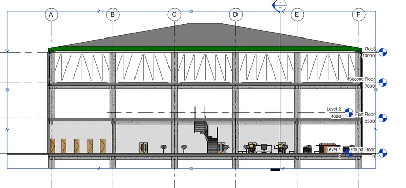
- Section 1 is Created as shown below.
- Similar, Other sections can be viewed as well.
- Go to View> Sheet.
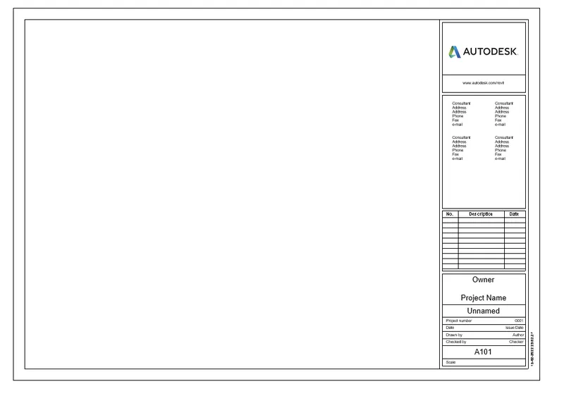
- select the A1 Metric Sheet>Ok.
- The Sheet will be Displayed on the screen.
- To change parameters such as Author, Checker etc on the Sheet also go to properties window and enter the required information>Apply.
- Go to View tab>view.
- Select the Floor Plan :Ground floor view.
- Click on add view to sheet.
- Place the view port on the sheet.
- Adjust the scale if required.
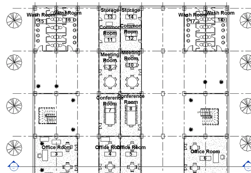
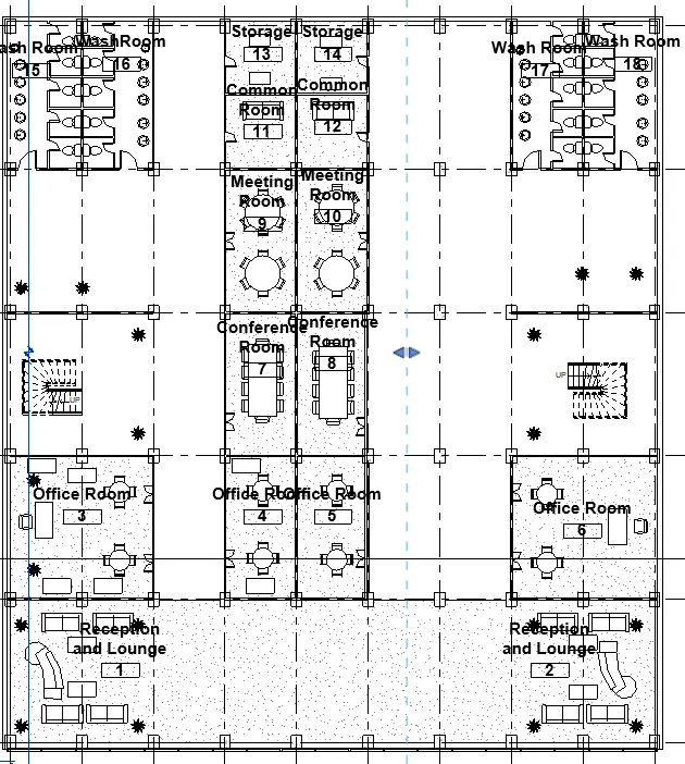
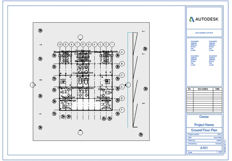
- Ground Floor Plan Sheet is Created.
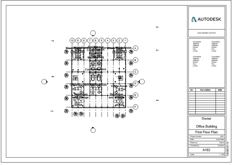
- Similarly All other required drawing sheets are created.
- First Floor Plan.
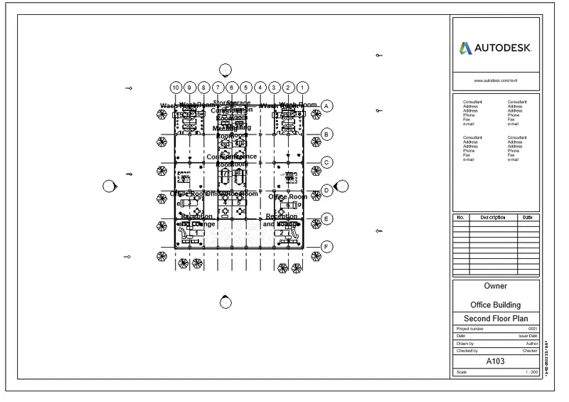
- Second Floor Plan.
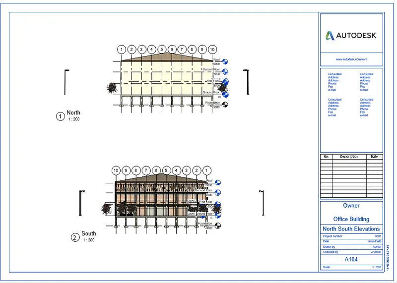
- North and South Elevations.
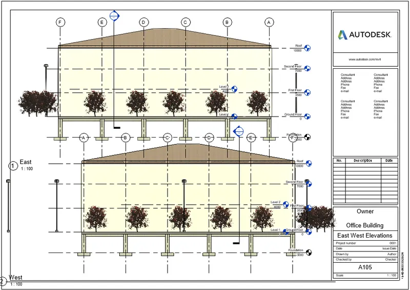
- East and West Elevations.
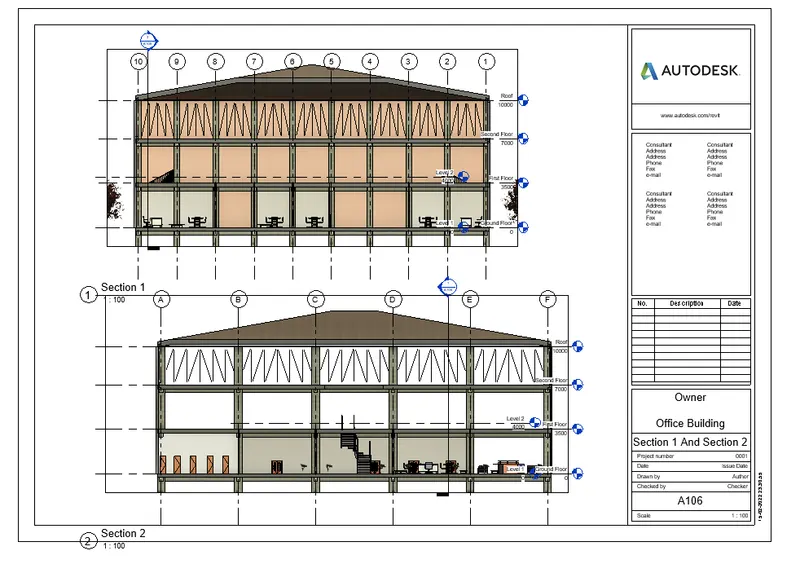
- Section 1 and 2.
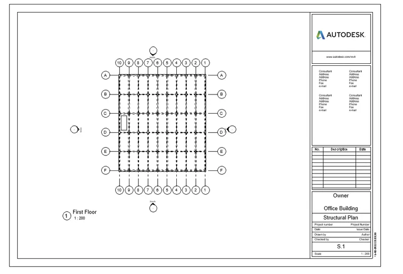
- Repeat the same process for creating structural model Sheets.
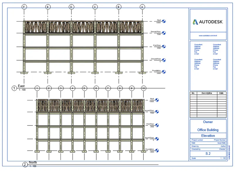
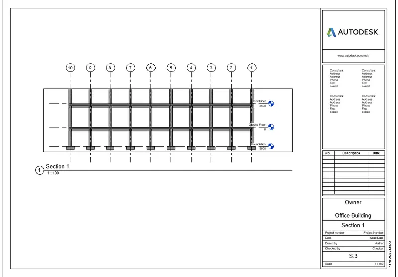
Result:
It has been Sucessfully illustrated how to create drawing sheets for the plan, Elevation, Section views in both the Architectural and Structural Models.
-------------------------------------------------------------------------------------------------------------------------------------------
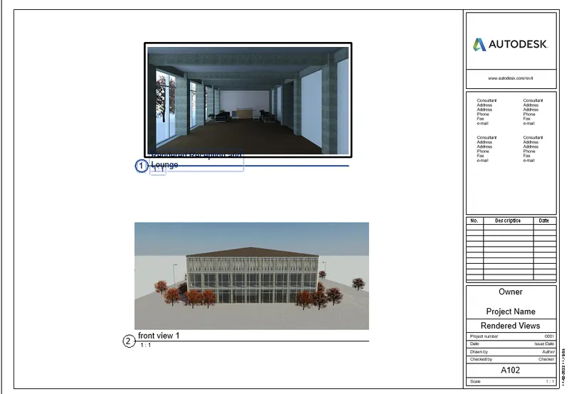
6) Using the Rendering settings, Render images of the 3D model produced and include the rendered images to the drawing sheets
a. Rendering from interior rooms
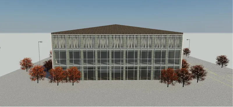
b. Rendering from out showing topographic features
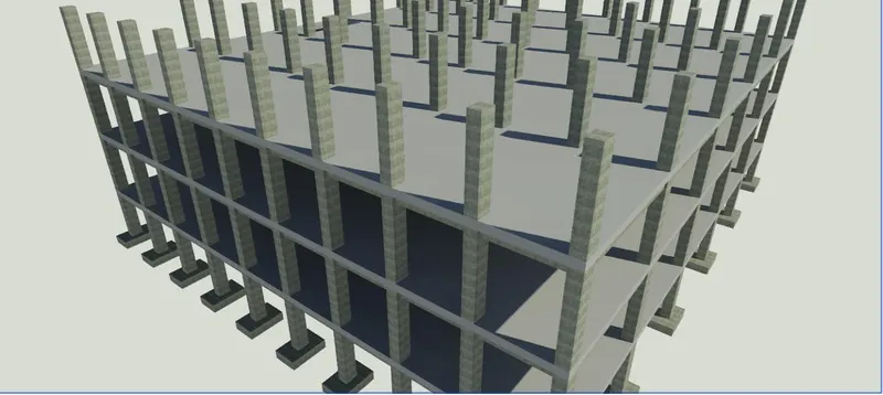
c. Rendering through structural framing.
AIM: To Render images of the 3D model and include them in drawing Sheets.
Introduction: The Procedure to render images of the 3D model in Revit is explained in detail and the final result is given.
Procedure:
- Select and open the Architectural model of the office Building.
- Project Browser> Floor Plans >Ground Floor.
- Go to View >3D View drop down list >Camera Options.
- Set the Camera in a suitable position to get the required view.
- Change Visual style to realistic.
- Rename the View Window as office room1 View.
- Go to View>Render.
- In the Rendering dialog box Select the Region option.
- Adjust the Region Window.
- Make other necessary changes in the rendering dialog box as per requirement>Render.
- The Rendered view is Ready.
- Similarly Create the rendered views of all other spaces in the Office Building Model.
- Go to View>Sheet.
- Select the A1 metric Sheet>Ok.
- The Sheet Will be Displayed on the Screen.
- To change parameters such as Author, Checker etc on the Sheet also go to properties window and enter the required information>Apply.
- Go to View tab>view.
- Select the desired view.
- Click on add view to sheet.
- Repeat the process to add other view to the Sheet.
- Similarly create other Sheets.
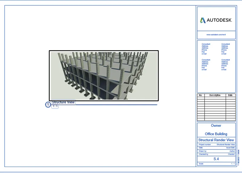
- Following the above Steps the Structural Rendered views and sheets can also be Created.
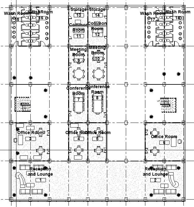
Realistic View
Reception and Lounge
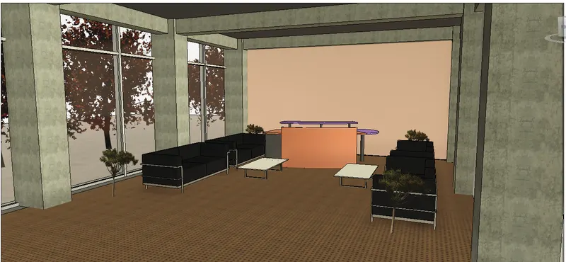
Office Room.
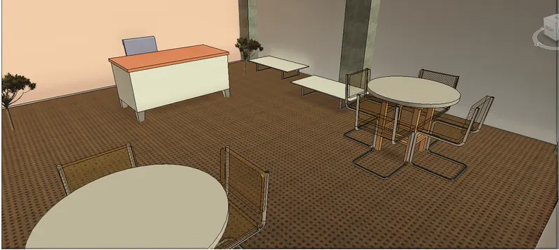
Conference Room.
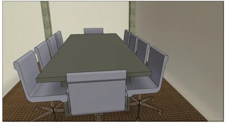
Wash Room.
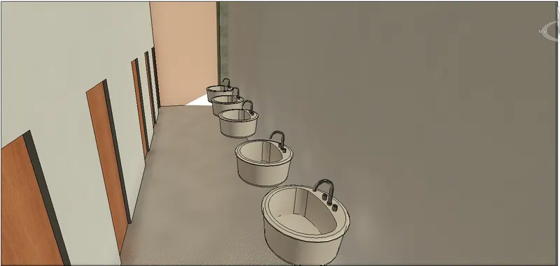
Rendered View.
Reception And Lounge
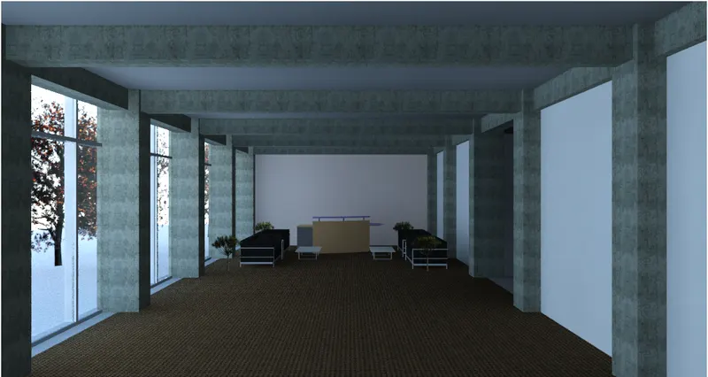
Front View
Structural rendered View And Sheet
Result:
It has been Sucessfully illustrated how to create rendered views of the interior and exterior of the Architectural and Structural models.
-------------------------------------------------------------------------------------------------------------------------------------------
7) Print the set of drawing sheets created and submit the drawings from the architecture and structure model.
AIM: To print the Set of drawing Sheets Created.
Introduction: The Procedure to render print the drawing sheets is explained in detail and the final result is given.
Procedure:
- Select and open the Architectural model of the office Building.
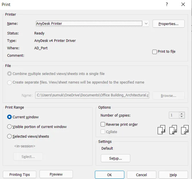
- Choose the Drawing sheet required to be printed or Saved as PDF File.
- Ctrl+P.
- The Print Dialog box will appear.
- Make adjustment/Changes as per Requirement.
- Go to Page SetUp and Make Necessary Changes>Ok.
- Save or print the Selected Revit Sheet>Submit.
- All other Sheets Can be Printed (Saved in PDF) format by following the above Steps.
RESULT:
It has been Successfully illustrated how to print or Save the Various views or Drawing Sheets in Revit.